EP1684385A2 - Système électrique pour un véhicule ferroviaire - Google Patents
Système électrique pour un véhicule ferroviaire Download PDFInfo
- Publication number
- EP1684385A2 EP1684385A2 EP06090004A EP06090004A EP1684385A2 EP 1684385 A2 EP1684385 A2 EP 1684385A2 EP 06090004 A EP06090004 A EP 06090004A EP 06090004 A EP06090004 A EP 06090004A EP 1684385 A2 EP1684385 A2 EP 1684385A2
- Authority
- EP
- European Patent Office
- Prior art keywords
- satellite
- plug
- contact
- complementary
- guide ring
- Prior art date
- Legal status (The legal status is an assumption and is not a legal conclusion. Google has not performed a legal analysis and makes no representation as to the accuracy of the status listed.)
- Withdrawn
Links
Images

Classifications
-
- H—ELECTRICITY
- H01—ELECTRIC ELEMENTS
- H01R—ELECTRICALLY-CONDUCTIVE CONNECTIONS; STRUCTURAL ASSOCIATIONS OF A PLURALITY OF MUTUALLY-INSULATED ELECTRICAL CONNECTING ELEMENTS; COUPLING DEVICES; CURRENT COLLECTORS
- H01R9/00—Structural associations of a plurality of mutually-insulated electrical connecting elements, e.g. terminal strips or terminal blocks; Terminals or binding posts mounted upon a base or in a case; Bases therefor
- H01R9/03—Connectors arranged to contact a plurality of the conductors of a multiconductor cable, e.g. tapping connections
-
- B—PERFORMING OPERATIONS; TRANSPORTING
- B60—VEHICLES IN GENERAL
- B60D—VEHICLE CONNECTIONS
- B60D1/00—Traction couplings; Hitches; Draw-gear; Towing devices
- B60D1/58—Auxiliary devices
- B60D1/62—Auxiliary devices involving supply lines, electric circuits or the like
-
- B—PERFORMING OPERATIONS; TRANSPORTING
- B61—RAILWAYS
- B61G—COUPLINGS; DRAUGHT AND BUFFING APPLIANCES
- B61G5/00—Couplings for special purposes not otherwise provided for
- B61G5/06—Couplings for special purposes not otherwise provided for for, or combined with, couplings or connectors for fluid conduits or electric cables
-
- H—ELECTRICITY
- H01—ELECTRIC ELEMENTS
- H01R—ELECTRICALLY-CONDUCTIVE CONNECTIONS; STRUCTURAL ASSOCIATIONS OF A PLURALITY OF MUTUALLY-INSULATED ELECTRICAL CONNECTING ELEMENTS; COUPLING DEVICES; CURRENT COLLECTORS
- H01R2201/00—Connectors or connections adapted for particular applications
- H01R2201/26—Connectors or connections adapted for particular applications for vehicles
-
- H—ELECTRICITY
- H01—ELECTRIC ELEMENTS
- H01R—ELECTRICALLY-CONDUCTIVE CONNECTIONS; STRUCTURAL ASSOCIATIONS OF A PLURALITY OF MUTUALLY-INSULATED ELECTRICAL CONNECTING ELEMENTS; COUPLING DEVICES; CURRENT COLLECTORS
- H01R27/00—Coupling parts adapted for co-operation with two or more dissimilar counterparts
Definitions
- the invention relates to an electrical system for a rail vehicle having at least two interconnected carriages, wherein each carriage is spanned by power supply lines and / or data lines from one end of the car to the other end of the car, the power supply lines and / or data lines of different carriages being interconnected via a cable connection, wherein the cable connection has at least one plug part and a device part which is complementary to the plug part, the plug part having a substantially hollow-cylindrical guide ring and the device part having a guide cutout complementary to the guide ring.
- UIC plug connection It is typically an 18-pin connector, wherein the contact pairs both power supply lines and data lines of different cars are contacted with each other.
- the invention is therefore based on the technical problem of providing a connector for rail vehicles, which is improved in terms of the performance of data lines, at the same time backward compatibility is ensured.
- the plug part has, outside the guide ring and spaced therefrom, a satellite plug element extending parallel to the guide ring, and the appliance part has a satellite device element complementary to the satellite plug element, the satellite plug element having at least one satellite plug contact and the satellite device element a satellite device contact, wherein the satellite plug contact and the satellite device contact are designed as complementary satellite contact pair.
- a connector used according to the invention allows the installation of additional lines, in particular data lines in a car or a rail vehicle formed from several cars. Because the satellite plug-in element is arranged outside the guide ring and at a distance therefrom, a plug part according to the invention can also still be plugged onto a conventional UIC device part. In this case, the satellite plug contact then remains uncontacted in the absence of a satellite device element. The same applies of course vice versa in the case of a device part according to the invention, in which a conventional UIC plug part is introduced. This achieves mechanical and electrical backward compatibility.
- equipment parts are installed at both ends of the wagon of a wagon, with two opposite parts of the equipment of different wagons being connected to each other via a cable connection equipped with two parts are connected.
- the connecting cable is permanently installed at one end of the car and at the other end has a plug part which is inserted into a device part of an opposite end of the car.
- the guide ring of a plug part and the guide recess complementary thereto are essentially hollow-cylindrical in the sense that polygons can also be used.
- a satellite contact pair can be designed either as an electrical contact pair or as an optical contact pair.
- the use of an optical contact pair is advantageous in that optical data lines have a considerably increased bandwidth compared to electrical data lines, i.e. the data transfer rates are considerably increased.
- the satellite device element and the satellite plug-in element may have from two to ten satellite contact pairs. These satellite contact pairs can also be set up in the context of several satellite device elements and satellite plug-in elements.
- the plug part has a plurality of, preferably two satellite plug elements lying opposite one another with respect to a center axis of the guide ring, wherein the device part has satellite device elements complementary to the satellite plug elements. This can be a total of a plurality of electrical or optical contact pairs and thus upgrade data lines in addition to the 18 poles of conventional UIC connectors.
- each carriage has a central processor unit, wherein at least one data line with a satellite device contact and / or a satellite plug contact is connected.
- a test routine can be carried out, by means of which it is detectable whether a plug-in plug-in connector part and device part to a satellite device element or satellite connector complementary satellite connector or satellite device element is contacted.
- the test routine tests whether, after production of the plug connection, an inventive satellite device element or satellite plug-in element has "found” a complementary satellite element. If so, the data communication between processor units of different cars is via the contacted satellite contact pair.
- the processor unit of a car with a satellite device element or satellite plug element according to the invention converts the operating program to routines which work with the conventional UIC plug-in connection. Thus, a functional backward compatibility is established.
- an electrical system for a rail vehicle wherein additional optical conductors are not arranged in the context of satellite elements, but rather in geometrically free areas of the insulating body of the male member and the device element or instead of a (conventional) pin and a contact socket.
- This can be set up, for example, in the case of UIC plug connections.
- complementary optical terminations or ends are set up in the respective insulators. It thus creates a hybrid UIC connector, wherein in addition to the electrical contact pairs and / or instead of one or more electrical Contact pairs an optical pair of contacts is set up, but no satellite elements are needed (but may be present). Otherwise, the above statements apply analogously, in particular with regard to backward compatibility.
- the opposite ends of the optical conductors are each provided with an optical diffusing lens, which cause an expansion of the light emitted from one end and a focusing of the expanded light received from the opposite end .
- an optical diffusing lens which cause an expansion of the light emitted from one end and a focusing of the expanded light received from the opposite end .
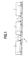
- Figure 1 can be seen a rail vehicle 1 with three interconnected car 2, each car is spanned by power supply lines 3 and data lines 3 from one end of the car to the other end of the car.
- the power supply lines and data lines are not shown separately in this schematic representation.
- the power supply lines 3 and data lines 3 of different cars are connected to each other via the cable connection 4.
- Each cable connection 4 has at opposite ends in each case a plug part 6.
- a Stekkerteil 6 a cable connection 4 is inserted into a device part 5 opposite each other car ends.
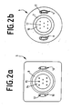
- FIG. 2 as well as a comparative examination of the figure parts 2a and 2b shows that the plug part 6 has a substantially hollow-cylindrical guide ring 7 and the device part 5 has a guide recess 8 complementary to the guide ring 7.
- the plug part 6 has outside of the guide ring 7 and spaced therefrom a parallel to the guide ring 7 extending Satellite plug 9 on.
- the device part 5 has a satellite plug element 9 complementary satellite device element 10.
- the device part 5 has an insulating body 14, in which electrical contact sockets 15 are embedded.
- the plug part 6 likewise has an insulating body 16, but contact pins 17 project beyond this insulating body 16.
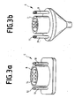
- each satellite plug-in element 9 has two satellite plug-in contacts 11 and each satellite device element 10 has two satellite device contacts 12, the satellite plug contacts 11 and the satellite device contacts 12 forming pairs of satellite contact pairs complementary to each other. At least one satellite contact pair is designed as an optical contact pair.
- the two satellite plug-in elements 9 are relative to each other with respect to the central axis of the guide ring 7.
- the satellite device elements 10 are set up in a complementary manner within the scope of the device part 5.
- FIG. 4 shows a connection between two carriages of a rail vehicle, wherein one of the two carriages (on the right side) has a conventional UIC device part. Due to the geometric design, as in the figures 2 3 and 3, the right-side plug part 6 of the cable connection 4 can be inserted into the conventional UIC device part 5 of the right-hand car 2. Both carriages 2 each have a central processor 13. After the preparation of the cable connection 4, the central processor 13 of the left-side car checks whether it is possible to communicate with the central processor 13 of the right-hand sidecar via the data line 3 of the cable connection 4.
- a plug connection used according to the invention can be all mechanical Have features of a conventional UIC connection, in particular also snap cover and lever lock in the context of a device part. 5
Landscapes
- Engineering & Computer Science (AREA)
- Mechanical Engineering (AREA)
- Transportation (AREA)
- Details Of Connecting Devices For Male And Female Coupling (AREA)
- Connector Housings Or Holding Contact Members (AREA)
- Electric Propulsion And Braking For Vehicles (AREA)
Applications Claiming Priority (1)
| Application Number | Priority Date | Filing Date | Title |
|---|---|---|---|
| DE200520000594 DE202005000594U1 (de) | 2005-01-19 | 2005-01-19 | Elektrisches System für ein Schienenfahrzeug |
Publications (2)
| Publication Number | Publication Date |
|---|---|
| EP1684385A2 true EP1684385A2 (fr) | 2006-07-26 |
| EP1684385A3 EP1684385A3 (fr) | 2009-11-04 |
Family
ID=34429103
Family Applications (1)
| Application Number | Title | Priority Date | Filing Date |
|---|---|---|---|
| EP06090004A Withdrawn EP1684385A3 (fr) | 2005-01-19 | 2006-01-11 | Système électrique pour un véhicule ferroviaire |
Country Status (2)
| Country | Link |
|---|---|
| EP (1) | EP1684385A3 (fr) |
| DE (1) | DE202005000594U1 (fr) |
Cited By (3)
| Publication number | Priority date | Publication date | Assignee | Title |
|---|---|---|---|---|
| CN106476818A (zh) * | 2016-10-28 | 2017-03-08 | 中车北京二七车辆有限公司 | 一种铁路冷藏集装箱运输设备 |
| EP4454969A1 (fr) * | 2023-04-28 | 2024-10-30 | SpeedInnov | Système de connexion optique à une extrémité d'une voiture d'un véhicule, véhicule ferroviaire et procédé de montage associés |
| EP4712276A1 (fr) * | 2024-09-16 | 2026-03-18 | Phillips Europe Spolka z Ograniczona Odpowiedzialnoscia | Fiche de connecteur élargi, douille et système |
Families Citing this family (2)
| Publication number | Priority date | Publication date | Assignee | Title |
|---|---|---|---|---|
| DE102008054349A1 (de) * | 2008-11-03 | 2010-05-06 | Wabco Gmbh | Steuerungsanordnung für ein Anhängefahrzeug, Anhängefahrzeug und Adapter |
| CN104742989A (zh) * | 2015-04-21 | 2015-07-01 | 南通市恒达机械制造有限公司 | 新型厂用组合式运输车 |
Family Cites Families (6)
| Publication number | Priority date | Publication date | Assignee | Title |
|---|---|---|---|---|
| US4017136A (en) * | 1975-08-25 | 1977-04-12 | Power Parts Company | Permanent tri-headed jumper cable for locomotives |
| US7015800B2 (en) * | 1995-11-09 | 2006-03-21 | Vehicle Enhancement Systems Inc. | System, apparatus and methods for data communication between vehicle and remote data communication terminal, between portions of vehicle and other portions of vehicle, between two or more vehicles, and between vehicle and communications network |
| DE29618000U1 (de) * | 1996-10-07 | 1996-12-12 | Erich Jaeger GmbH & Co KG, 61350 Bad Homburg | Steckdose |
| US6558167B2 (en) * | 2001-01-22 | 2003-05-06 | Grote Industries, Inc. | Nosebox with interchangeable connector assemblies for tractors and trailers |
| WO2003030309A1 (fr) * | 2001-10-02 | 2003-04-10 | Reese Products, Inc. | Appareil de distribution d'alimentation pour vehicule equipe d'une remorque |
| ATE302134T1 (de) * | 2001-10-16 | 2005-09-15 | Voith Turbo Scharfenberg Gmbh | Elektrischer steckverbinder |
-
2005
- 2005-01-19 DE DE200520000594 patent/DE202005000594U1/de not_active Expired - Lifetime
-
2006
- 2006-01-11 EP EP06090004A patent/EP1684385A3/fr not_active Withdrawn
Cited By (4)
| Publication number | Priority date | Publication date | Assignee | Title |
|---|---|---|---|---|
| CN106476818A (zh) * | 2016-10-28 | 2017-03-08 | 中车北京二七车辆有限公司 | 一种铁路冷藏集装箱运输设备 |
| CN106476818B (zh) * | 2016-10-28 | 2018-10-16 | 中车北京二七车辆有限公司 | 一种铁路冷藏集装箱运输设备 |
| EP4454969A1 (fr) * | 2023-04-28 | 2024-10-30 | SpeedInnov | Système de connexion optique à une extrémité d'une voiture d'un véhicule, véhicule ferroviaire et procédé de montage associés |
| EP4712276A1 (fr) * | 2024-09-16 | 2026-03-18 | Phillips Europe Spolka z Ograniczona Odpowiedzialnoscia | Fiche de connecteur élargi, douille et système |
Also Published As
| Publication number | Publication date |
|---|---|
| DE202005000594U1 (de) | 2005-04-07 |
| EP1684385A3 (fr) | 2009-11-04 |
Similar Documents
| Publication | Publication Date | Title |
|---|---|---|
| DE69826202T2 (de) | Kabelverbinderanordnung | |
| DE102008038641A1 (de) | Vorrichtung zur Herstellung einer Verbindung | |
| DE102022112463B4 (de) | Vorrichtung und Anordnung zum Überprüfen der Funktionsfähigkeit einer Ladestation | |
| DE202008014989U1 (de) | Vorrichtung zur Herstellung einer Verbindung | |
| WO2021028150A1 (fr) | Couplage de traction électrique et couplage de traction équipé dudit couplage de traction électrique | |
| EP1913656B1 (fr) | Connecteur de charge | |
| DE29814208U1 (de) | Kontakteinsatz für Industriestecker | |
| WO2018184834A1 (fr) | Procédé de réalisation d'un câblage sur une matrice composée de dispositifs de raccordement de conducteur et ensemble de bornes serre-fils | |
| DE202013006512U1 (de) | Elektrische Zugkupplung | |
| EP1523790A1 (fr) | Connexion par enfichage pourvue d'un dispositif de contact supplementaire, notamment pour la transmission de donnees | |
| DE3537944C2 (fr) | ||
| DE102022121178A1 (de) | Schaltsteckverbindersystem- und Geräteverkabelung | |
| EP1414117B1 (fr) | Arrangement d'un connecteur avec deux fiches différentes adaptées à deux différents types de prises | |
| DE2356840A1 (de) | Verlaengerungsvorrichtung fuer kontaktelemente von elektrischen steckverbindungen | |
| DE3127246C2 (fr) | ||
| DE202016105823U1 (de) | Steckverbindung | |
| DE102010039957B4 (de) | Trennbuchsenanordnungen und Trennadapter mit einer Trägerplatte und einer oder mehreren darin angebrachten Trennbuchsen der Trennbuchsenanordnungen | |
| DE10213990B4 (de) | Elektrische Anschluss- oder Verbindungsklemme | |
| DE102024201360B3 (de) | Adapter zur Verbindung eines Ladeanschlusses eines elektrischen Kraftfahrzeugs mit einem Ladeanschluss einer Ladestation | |
| EP1328422B1 (fr) | Point nodal d'un bus de donnees d'un vehicule automobile | |
| DE2418634A1 (de) | Elektrische steckvorrichtungen | |
| DE2706447A1 (de) | Steckverbinder fuer eine geschlossene sammelschienenanordnung | |
| DE202018106611U1 (de) | Datenübertragungs- und/oder Ladekabel | |
| EP0286697B1 (fr) | Connexion à fiche multipole séparable pour le transfert de courants électriques, utilisée par exemple pour des automobiles | |
| EP1652274B1 (fr) | Systeme de connexion par enfichage comportant un dispositif de verrouillage integre |
Legal Events
| Date | Code | Title | Description |
|---|---|---|---|
| PUAI | Public reference made under article 153(3) epc to a published international application that has entered the european phase |
Free format text: ORIGINAL CODE: 0009012 |
|
| AK | Designated contracting states |
Kind code of ref document: A2 Designated state(s): AT BE BG CH CY CZ DE DK EE ES FI FR GB GR HU IE IS IT LI LT LU LV MC NL PL PT RO SE SI SK TR |
|
| AX | Request for extension of the european patent |
Extension state: AL BA HR MK YU |
|
| PUAL | Search report despatched |
Free format text: ORIGINAL CODE: 0009013 |
|
| AK | Designated contracting states |
Kind code of ref document: A3 Designated state(s): AT BE BG CH CY CZ DE DK EE ES FI FR GB GR HU IE IS IT LI LT LU LV MC NL PL PT RO SE SI SK TR |
|
| AX | Request for extension of the european patent |
Extension state: AL BA HR MK YU |
|
| AKX | Designation fees paid | ||
| STAA | Information on the status of an ep patent application or granted ep patent |
Free format text: STATUS: THE APPLICATION IS DEEMED TO BE WITHDRAWN |
|
| 18D | Application deemed to be withdrawn |
Effective date: 20100505 |
|
| REG | Reference to a national code |
Ref country code: DE Ref legal event code: 8566 |