EP1684395A2 - Mittelspannung/Niederspannung - Transformatorenstation - Google Patents
Mittelspannung/Niederspannung - Transformatorenstation Download PDFInfo
- Publication number
- EP1684395A2 EP1684395A2 EP05291911A EP05291911A EP1684395A2 EP 1684395 A2 EP1684395 A2 EP 1684395A2 EP 05291911 A EP05291911 A EP 05291911A EP 05291911 A EP05291911 A EP 05291911A EP 1684395 A2 EP1684395 A2 EP 1684395A2
- Authority
- EP
- European Patent Office
- Prior art keywords
- transformer
- station according
- transformer station
- network
- homopolar
- Prior art date
- Legal status (The legal status is an assumption and is not a legal conclusion. Google has not performed a legal analysis and makes no representation as to the accuracy of the status listed.)
- Granted
Links
- 238000004804 winding Methods 0.000 claims abstract description 49
- 230000004224 protection Effects 0.000 claims description 20
- 230000007935 neutral effect Effects 0.000 claims description 18
- 230000004907 flux Effects 0.000 claims description 17
- 238000010586 diagram Methods 0.000 claims description 14
- 230000008878 coupling Effects 0.000 claims description 11
- 238000010168 coupling process Methods 0.000 claims description 11
- 238000005859 coupling reaction Methods 0.000 claims description 11
- 230000006641 stabilisation Effects 0.000 claims description 7
- 239000004020 conductor Substances 0.000 claims description 6
- 238000011105 stabilization Methods 0.000 claims description 6
- 238000005259 measurement Methods 0.000 claims description 2
- 238000003475 lamination Methods 0.000 claims 1
- 239000003921 oil Substances 0.000 abstract description 5
- 230000007547 defect Effects 0.000 abstract description 3
- 239000002480 mineral oil Substances 0.000 abstract description 2
- 235000010446 mineral oil Nutrition 0.000 abstract description 2
- 230000001131 transforming effect Effects 0.000 abstract 1
- 230000000694 effects Effects 0.000 description 6
- 230000009466 transformation Effects 0.000 description 6
- 230000008901 benefit Effects 0.000 description 4
- 230000008859 change Effects 0.000 description 4
- 230000001419 dependent effect Effects 0.000 description 3
- 238000001514 detection method Methods 0.000 description 3
- 230000005611 electricity Effects 0.000 description 3
- 230000001965 increasing effect Effects 0.000 description 3
- 230000009467 reduction Effects 0.000 description 3
- 230000035945 sensitivity Effects 0.000 description 3
- 238000009933 burial Methods 0.000 description 2
- 230000001939 inductive effect Effects 0.000 description 2
- 230000000670 limiting effect Effects 0.000 description 2
- 230000000750 progressive effect Effects 0.000 description 2
- 230000002829 reductive effect Effects 0.000 description 2
- 239000003990 capacitor Substances 0.000 description 1
- 230000001186 cumulative effect Effects 0.000 description 1
- 230000003247 decreasing effect Effects 0.000 description 1
- 230000001627 detrimental effect Effects 0.000 description 1
- 238000010891 electric arc Methods 0.000 description 1
- 238000003780 insertion Methods 0.000 description 1
- 230000037431 insertion Effects 0.000 description 1
- 238000009413 insulation Methods 0.000 description 1
- 230000010354 integration Effects 0.000 description 1
- 238000002955 isolation Methods 0.000 description 1
- 239000007788 liquid Substances 0.000 description 1
- 239000000696 magnetic material Substances 0.000 description 1
- 238000004519 manufacturing process Methods 0.000 description 1
- 239000000463 material Substances 0.000 description 1
- 230000004048 modification Effects 0.000 description 1
- 238000012986 modification Methods 0.000 description 1
- 230000002093 peripheral effect Effects 0.000 description 1
- 230000001681 protective effect Effects 0.000 description 1
- 230000000717 retained effect Effects 0.000 description 1
- 230000000087 stabilizing effect Effects 0.000 description 1
- 230000001960 triggered effect Effects 0.000 description 1
- 238000011144 upstream manufacturing Methods 0.000 description 1
Images


Classifications
-
- H—ELECTRICITY
- H02—GENERATION; CONVERSION OR DISTRIBUTION OF ELECTRIC POWER
- H02H—EMERGENCY PROTECTIVE CIRCUIT ARRANGEMENTS
- H02H9/00—Emergency protective circuit arrangements for limiting excess current or voltage without disconnection
- H02H9/08—Limitation or suppression of earth fault currents, e.g. Petersen coil
Definitions
- the present invention relates to a medium voltage / low voltage (MV / LV) electrical transformer station.
- MV / LV medium voltage / low voltage
- the MT 6 lines were essentially aerial and made of bare conductors. Such lines are exposed to climatic constraints (storms, storms, ). To make the networks less vulnerable and thus improve the quality of service, the electricity distributors have partially or completely replaced these overhead lines with underground lines consisting of MV cable with a grounded peripheral screen. On the other hand, if the reliability of the networks was greatly improved, it became apparent that the capacitive effect of these cables could be detrimental to the protection of people and goods, due to a strong increase in the fault current. in case of a short circuit between a phase of the network and the earth. To overcome this drawback, the electricity distributors have inserted an inductor between the neutral of the MV network and the earth, so as to compensate for the capacitive current occurring during the phase-to-earth faults.
- this inductor 8 is located in the high voltage / medium voltage source station, typically connected to the neutral point of the secondary winding of the high voltage / medium voltage transformer 2. In parallel with this inductor 8 is also connected a resistor 9 for enabling the detection of faults between phase and earth.
- the capacitive effect of the cables vis-à-vis the earth is symbolized by capacitors 10 of value C.
- a capacitive current Ic will flow in the failure. This current can reach values of the order of one hundred amperes and generate contact voltages or dangerous step voltages depending on the quality of the earth connections instead of the fault.
- the currents IC and IL will cancel each other out and the ground phase fault current Id only includes the current IR, of a value generally less than or equal to 10 A, in fact essentially dependent on the value of the resistor 9 and chosen value just sufficient to allow the operation of homopolar protections of the source station.
- the capacitive effect of the cables is thus eliminated and the value of the fault current Id is controlled by the operator.
- the inductor 8 is generally adjustable and permanently given to the value effective of the capacitive current homopolar of the network thanks to an automatic device.
- this current IR which is substantially the fault current Id, is increased because of the resistance of the circuits borrowed by the currents IL, IR and IC caused by the defect, and can no longer be controllable in the case of unusually large networks.
- the object of the present invention is to avoid these drawbacks and to allow network extensions or the progressive burial of the network lines without having to intervene in the source station, or at least minimizing the modifications to be made to it. It relates to a medium voltage / low voltage transformer station (or MT / LV), in which is integrated a homopolar current compensation means generated by the network portion to which the station is connected.
- the subject of the invention is an MV / LV electrical transformer station comprising an MV / LV transformer, said station comprising means for compensating the zero-sequence capacitive current generated by an MV network portion. fixed length to which said transformer is likely to be connected, in case of a fault between a phase and the earth located on this network.
- a 10 kV underground network with earth-shielded cables generates a capacitive current of 1.5 A / km in case of a frank fault between a phase and the earth.
- the transformation station object of the invention makes it possible to economically provide the compensation of a current for values up to 15 A. It thus covers a portion of network of length equal to 10 km.
- the density of housing in Western countries is such that the number of substations tends to be greater than or equal to 1 MV / LV substation per km of network.
- the MV / LV transformer is an oil bath transformer.
- the compensation means can be integrated in the oil bath of the transformer.
- the homopolar current compensation means is an inductor.
- the characteristics of the inductance can be chosen to, on the one hand, ensure the compensation of the zero sequence current of a portion of MV network on which is connected station and, secondly, do not disturb the operation of homopolar protection located in the source station that supplies the MV network.
- the inductor can be single-phase and connected between the neutral point constituted by the MV windings of the transformer and the earthing of the substation.
- the single-phase inductance may consist of a solenoid wrapped with a magnetic shielding.
- the coupling of the MV windings of the transformer is of the zigzag type.
- a tertiary triangle coupling stabilization coil may further be added to the transformer.
- the transformer has a tank and comprises, on a side face of said tank a first cabinet in which are the MV network connection terminals allowing a connection diagram in frame passage or antenna , and a second cabinet comprising a LV distribution board allowing the evacuation of energy from several LV cables.
- the transformer may further incorporate a protection device associating three striker MV fuses, a three-phase disconnecting device, and a device for detecting fault currents between phase and ground of the active part of the transformer.
- the mass of the active part of the inductor can be isolated from the station envelope and electrically connected to the ground of the active part of the transformer.
- the inductance can, depending on the characteristics required of it, be bulky with respect to the active part of the transformer which contains it, which amounts to greatly increasing the size of the apparatus as well as the bulk of the position in which it is integrated.
- the coupling of the transformer must be such that it has MV windings connected in zigzag manner so as not to saturate the magnetic circuit nor create homopolar flux, which flow would cause losses by eddy currents in the neighboring parts of the circuit magnetic and degrade the quality factor of the system.
- a stabilization winding tertiary winding connected in a triangle, is necessary to prevent the currents likely to appear in the neutral of the secondary winding of the transformer to convert into current in the neutral of the primary winding.
- the compensation device no longer consists of a solenoid separate from the active part of the transformer, but is directly integrated therein.
- the primary windings of the transformer are coupled in a star and the circuit magnetic transformer comprises at least one stream return leg arranged to channel the homopolar flux, said leg comprising at least one gap to adjust the reluctance of the circuit followed by the homopolar flux
- a measurement winding consisting of at least one turn of a conductor can be wound on said loop leg of the magnetic circuit.
- a cut-off device BT may also be provided downstream of the transformer LV windings, this cut-off device being arranged to be triggered by a zero-sequence voltage relay integrated in the substation and using the image of the zero-sequence voltage delivered by the transformer. said measuring winding.
- the magnetic circuit comprises two homopolar flux return legs, arranged substantially symmetrically on either side of the transformer windings.
- the flux return legs may consist of stacked magnetic sheet sections supported on the ends of yokes connecting the ends of the magnetic cores on which are wound the primary windings of the transformer.
- Air gaps may be provided between the different sections and between the end sections and the yokes of the magnetic circuit, said gaps being arranged to obtain the reluctance of the circuit adapted to the desired zero sequence impedance.
- said transformer comprises a main magnetic circuit consisting of three cores whose ends are connected by two yokes, and two flux return legs. having wings extending from the yokes of the main magnetic circuit.
- the subject of the invention is also a medium-voltage electrical network comprising at least one transformer station as described above, and at least one transformer station comprising no means for compensating the zero-sequence capacitive current.
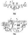
- FIG. 3 shows an MT 12 network section, partially or wholly of an underground cable.
- This section 12 is powered by a source station A identified 1 under normal operating conditions.
- the homopolar capacitive current corresponding to this line section is compensated by the Petersen coil located in this source station A.
- the switch 14 and closing the switch 15 the section is refueled from the source station B.
- Multiplying the grounding points of the neutral of the MV network can lead to a loss of sensitivity of the homopolar protection 5 that equips each line feeder 4 at the source station 1. As shown in FIG. part of the current due to the fault and which closed initially through the source station will now be diverted to the compensation device 17 equipping one or more transformer stations MT / BT 16, and therefore will not be seen by the homopolar protection 5 .
- a transformer station includes among its components an MV / LV transformer, usually in an oil bath.
- Figure 5 shows the electrical diagram of the transformer equipping the station according to a first embodiment of the invention.
- This transformer 18 comprises primary windings or MT 19 and secondary windings or LV 20.
- the windings of the three phases can be connected in a triangle, star or zigzag. Zigzag coupling is particularly interesting here because it provides very low zero-sequence impedance and therefore can be used to create a neutral point.
- the transformer station object of the invention will therefore comprise a three-phase transformer whose primary windings 19 are connected in a zigzag-type coupling. It is then possible to insert between the neutral point 21 thus obtained in the transformer and the earth of the substation a single-phase inductance 17 of selected characteristics, which will compensate a certain value of the homopolar capacitive current of the network by delivering for example a reactive current of 15 A under full homopolar voltage.
- This inductance can be isolated in the mineral oil, which has the advantage of allowing a reduction in its size and also to be inserted directly into the transformer tank. According to a preferred embodiment, it consists of a solenoid made from the winding of an insulated conductor wire.
- a magnetic shield is arranged around the solenoid so as to allow the lines of the field to close in a controlled manner.
- the insertion of an inductor between the neutral of the transformer and the earth requires certain precautions, especially when the MV / LV transformer of the substation is likely to supply an unbalanced LV load, which is generally the case in rural areas or when the appearance of an insulation fault on the LV network.
- This imbalance is shown in FIG. 5 by a current flowing in the neutral LV equal to 3 times the homopolar current Io.
- this homopolar LV current could generate a homopolar current on the MT side which, passing through the compensation inductor 17, would create an undesirable homopolar voltage.
- the transformer 18 is provided with tertiary windings 22 called stabilization windings which are connected in a triangle. In this way, the LV earth current Io will be compensated by a circulation current in the triangle of the stabilization windings 22 without influencing the MV circuits.
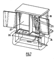
- a transformer station usually consists of an enclosure, which contains various components, the main ones of which are a MV switchgear and switchgear, a MV / LV transformer, a LV distribution board.
- the transformation station which is the subject of the invention does not comprise any MV switchgear and consists essentially of the transformer, which has on the largest side face of its tank 23 a first cabinet 24 in which are the connection terminals to the network MT 25, and a second cabinet 26 comprising the distribution table BT 27.
- connection to the network can be done according to an antenna scheme, the transformer having three MT 25 crossings. But it can also be done according to a diagram in passage or called in cut. In this case, the transformer is equipped with six MT 25 traverses associated in pairs.
- the direct connection of the transformer to the MV network involves some provisions against the effects of internal faults on the transformer. Indeed, the MV supply network being particularly intensive, an electric arc appearing in the oil bath of the transformer could cause thermal and mechanical effects resulting in external manifestations dangerous for the vicinity of the station. It is therefore expected that the transformer incorporates a protection device and cutoff as described in patents No. 0817346 and 2084549 filed by the applicant. This device combines MT 28 protective fuses provided with strikers 29, a three-phase MV disconnection device 30, and a device for detecting an earth fault current 31.
- the mass thereof consisting of the magnetic shielding which surrounds it, is isolated from the general mass of the station and is connected by means of a galvanic connection 32 with the mass of the active part of the transformer to the detection device of a earth fault current 31.
- the electrical characteristic of the fuses 28 is chosen so that they are insensitive to the current that will pass through them during the various faults between phase and earth that will appear on the network.
- Such a transformer station can be indifferently equipped with or without a compensation inductor 17, depending on the needs of the network evolution project.
- the tank 23, the cabinets 24 and 26, the equipment 25 and 27, the internal protection and disconnection device consisting of fuses 28, strikers 29, the disconnector 30 and the fault current detection device to the ground 31 remain common.
- Transformer 18 then has MT 19 primary windings coupled in a triangle, windings secondary BT 20 star, and does not include stabilizing windings 22.
- FIG. 8 corresponds to an explanatory diagram of the principle of another embodiment of the invention. Yet another embodiment, optimized, will be given later.
- This FIG. 8 diagrammatically represents the transformer 100, which is of the type immersed in a dielectric liquid contained in a tank 102.
- the coupling of the primary windings 105 connected to the network MT 110 via the terminals 103 is a star coupling, the neutral point 104 being intended to be connected to the earth of the station.
- the magnetic circuit 6 of the MV / LV transformer is in the form of a scale with two uprights 120 and generally parallel bars 107, 108.
- the amounts 120 form the yokes of the transformer while the bars form as many magnetic cores 107 that the circuit has phases (here 3) and additional legs for the return of homopolar flux.
- the cores 107 receiving the MV windings 105 are sized to accept without saturation phenomenon a winding voltage equal to the network voltage. Indeed, during a frank defect between phase and earth on the MV network, the windings connected between the neutral and the healthy phases see a voltage multiplied by the factor ⁇ 3.
- An additional leg 108 disposed opposite the end core 107, allows looping of the homopolar flux generated when a fault occurs between a phase of the MT network 110 and the earth.
- This leg 108 includes air gaps 109 distributed, to control the reluctance of the circuit traversed by the homopolar flux.
- the homopolar impedance seen on the MV side of the transformer is then directly dependent on this reluctance and can be adjusted according to the characteristics required.
- a measuring winding 112 on the fourth leg 108 comprising air gaps 109.
- This winding generates a voltage u o 'delivered between terminals 113, dependent on the number of turns retained, but also directly proportional to the zero-sequence voltage present on the MV network 110 during a fault between one of the phases and the earth.
- This voltage information can be useful for several applications.
- a directional fault detector which, having this voltage u o 'as well as currents of the different phases of the network, informs about the situation of the fault that appeared between one of the phases of the network. and the land, either upstream or downstream of the substation.
- the MT 110 grid neutral regime becomes an isolated neutral regime. It becomes necessary to replace the protections intervening in current operation and which are no longer connected to the island network, another protection capable of ensuring the safety of personnel and property in case of a fault between a phase MT and land.
- the generator 115 is connected to the LV windings 111 of the transformer 100 through a breaking device 116, which can be a circuit breaker, controlled by a zero-sequence voltage overcurrent protection relay 117.
- This homopolar relay can then directly use the voltage information u o 'without requiring, as is the case in a conventional mounting, the use of three star-coupled potential transformers.
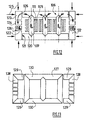
- the magnetic circuit 106 here comprises the three identical cores 107, around which are positioned the primary windings 105 as well as the secondary windings 111 of the transformer.
- the yokes 120 which receive the cores 107 are extended on either side and have ends 121 with a 90 ° cut.
- Two return legs 122 for looping the homopolar flux ⁇ 0 are arranged symmetrically and consist of sections 123 and 124. These sections, made just like the other parts of the magnetic circuit by a stack of magnetic sheet, are held together and positioned together. against the ends 122 of the yokes 120 by clamping devices 125 obtainable from threaded tie rods. These devices are symbolized here by the mechanical actions they exert on the magnetic circuit.
- the sections 123 have a length at least equal to the width of the yokes 120.
- the sections 124 have a length depending on the number of gaps 126 and the thickness of these gaps necessary to obtain a reluctance of the magnetic circuit allowing to achieve the desired homopolar impedance.
- the air gaps 126 are obtained by inserting plates of defined thickness of non-magnetic material between the ends of the sections and may be of different thicknesses if necessary.
- the section of the sections 123 and 124 is at least sufficient to allow the passage without saturation phenomenon of a flow equal to 1.5 times the homopolar flux ⁇ 0 likely to pass through each core 107.
- FIG. 13 shows a principle by which a conventional main magnetic circuit 127 of geometry commonly used for three-phase transformers, to which is added on either side of the return legs 128, which integrate then two wings 129 extending the cylinder heads 130 of the main circuit 127.
Landscapes
- Emergency Protection Circuit Devices (AREA)
- Transformers For Measuring Instruments (AREA)
Priority Applications (1)
| Application Number | Priority Date | Filing Date | Title |
|---|---|---|---|
| EP20050291911 EP1684395B1 (de) | 2005-01-19 | 2005-09-15 | Mittelspannung/Niederspannung - Transformatorenstation |
Applications Claiming Priority (3)
| Application Number | Priority Date | Filing Date | Title |
|---|---|---|---|
| FR0550158A FR2881002B1 (fr) | 2005-01-19 | 2005-01-19 | Poste de transformation electrique moyenne tension/basse tension |
| EP05290581A EP1684394B1 (de) | 2005-01-19 | 2005-03-16 | Mittelspannung/Niederspannung - Transformatorenstation |
| EP20050291911 EP1684395B1 (de) | 2005-01-19 | 2005-09-15 | Mittelspannung/Niederspannung - Transformatorenstation |
Publications (3)
| Publication Number | Publication Date |
|---|---|
| EP1684395A2 true EP1684395A2 (de) | 2006-07-26 |
| EP1684395A3 EP1684395A3 (de) | 2007-09-05 |
| EP1684395B1 EP1684395B1 (de) | 2015-04-22 |
Family
ID=36190515
Family Applications (1)
| Application Number | Title | Priority Date | Filing Date |
|---|---|---|---|
| EP20050291911 Expired - Lifetime EP1684395B1 (de) | 2005-01-19 | 2005-09-15 | Mittelspannung/Niederspannung - Transformatorenstation |
Country Status (1)
| Country | Link |
|---|---|
| EP (1) | EP1684395B1 (de) |
Cited By (6)
| Publication number | Priority date | Publication date | Assignee | Title |
|---|---|---|---|---|
| EP2330709A1 (de) | 2009-12-02 | 2011-06-08 | ABB Research Ltd. | Erdfehlerhandhabung in Stromverteilungssystemen mit gemischten unter- und oberirdischen Stromleitungen |
| CN102170121A (zh) * | 2011-04-21 | 2011-08-31 | 华北电力大学(保定) | 带修正电压互感器的消谐器 |
| EP2530804A1 (de) | 2011-06-01 | 2012-12-05 | ABB Research Ltd. | Verbesserte Erdfehlerhandhabung in Stromverteilungssystemen mit gemischten unter- und oberirdischen Stromleitungen |
| WO2020043955A1 (en) | 2018-08-30 | 2020-03-05 | Tammerfast Oy | Transmission cable joint for a medium voltage underground cable system |
| FR3088476A1 (fr) * | 2018-11-08 | 2020-05-15 | Thales | Procede de detection et de transmission d'information de panne dormante |
| US20220102068A1 (en) * | 2019-02-04 | 2022-03-31 | Ensto Oy | Arc suppression coil and method for grounding |
Citations (1)
| Publication number | Priority date | Publication date | Assignee | Title |
|---|---|---|---|---|
| EP1684394B1 (de) | 2005-01-19 | 2009-05-06 | Societe Nouvelle Transfix Toulon | Mittelspannung/Niederspannung - Transformatorenstation |
Family Cites Families (1)
| Publication number | Priority date | Publication date | Assignee | Title |
|---|---|---|---|---|
| FR2697341B1 (fr) * | 1992-10-26 | 1995-01-13 | Electricite De France | Procédé et dispositif de mesure de l'accord et du désaccord de compensation d'un réseau de distribution électrique. |
-
2005
- 2005-09-15 EP EP20050291911 patent/EP1684395B1/de not_active Expired - Lifetime
Patent Citations (1)
| Publication number | Priority date | Publication date | Assignee | Title |
|---|---|---|---|---|
| EP1684394B1 (de) | 2005-01-19 | 2009-05-06 | Societe Nouvelle Transfix Toulon | Mittelspannung/Niederspannung - Transformatorenstation |
Cited By (14)
| Publication number | Priority date | Publication date | Assignee | Title |
|---|---|---|---|---|
| WO2011067255A1 (en) * | 2009-12-02 | 2011-06-09 | Abb Research Ltd | Ground fault handling in power distribution systems with mixed underground and aerial power lines |
| EP2330709A1 (de) | 2009-12-02 | 2011-06-08 | ABB Research Ltd. | Erdfehlerhandhabung in Stromverteilungssystemen mit gemischten unter- und oberirdischen Stromleitungen |
| CN102170121A (zh) * | 2011-04-21 | 2011-08-31 | 华北电力大学(保定) | 带修正电压互感器的消谐器 |
| CN102170121B (zh) * | 2011-04-21 | 2014-10-29 | 华北电力大学(保定) | 带修正电压互感器的消谐器 |
| EP2530804A1 (de) | 2011-06-01 | 2012-12-05 | ABB Research Ltd. | Verbesserte Erdfehlerhandhabung in Stromverteilungssystemen mit gemischten unter- und oberirdischen Stromleitungen |
| EP3844851A4 (de) * | 2018-08-30 | 2022-06-01 | Tammerfast OY | Übertragungskabelverbindung für ein unterirdisches mittelspannungskabelsystem |
| WO2020043955A1 (en) | 2018-08-30 | 2020-03-05 | Tammerfast Oy | Transmission cable joint for a medium voltage underground cable system |
| US11670931B2 (en) | 2018-08-30 | 2023-06-06 | Tammerfast Oy | Transmission cable joint for a medium voltage underground cable system |
| CN112640237A (zh) * | 2018-08-30 | 2021-04-09 | 塔默法斯特公司 | 用于中压地下电缆系统的传输电缆接头 |
| CN112640237B (zh) * | 2018-08-30 | 2023-02-17 | 塔默法斯特公司 | 用于中压地下电缆系统的传输电缆接头 |
| FR3088476A1 (fr) * | 2018-11-08 | 2020-05-15 | Thales | Procede de detection et de transmission d'information de panne dormante |
| US11005258B2 (en) | 2018-11-08 | 2021-05-11 | Thales | Method for detecting and transmitting dormant failure information |
| EP3654045A1 (de) * | 2018-11-08 | 2020-05-20 | Thales | Detektions- und übertragungsverfahren von information über einen schlafenden fehler |
| US20220102068A1 (en) * | 2019-02-04 | 2022-03-31 | Ensto Oy | Arc suppression coil and method for grounding |
Also Published As
| Publication number | Publication date |
|---|---|
| EP1684395B1 (de) | 2015-04-22 |
| EP1684395A3 (de) | 2007-09-05 |
Similar Documents
| Publication | Publication Date | Title |
|---|---|---|
| US20030210135A1 (en) | Protecting medium voltage inductive coupled device from electrical transients | |
| CN102545171A (zh) | 一种多绕组可调电抗器及其单相接地故障切除方法 | |
| FR2736767A1 (fr) | Dispositif pour la compensation d'un courant de mise a la terre d'un reseau electrique polyphase | |
| EP1974362A1 (de) | Generator-isolator mit integriertem widerstand | |
| EP1684394B1 (de) | Mittelspannung/Niederspannung - Transformatorenstation | |
| EP1684395B1 (de) | Mittelspannung/Niederspannung - Transformatorenstation | |
| EP1107269B1 (de) | Drehstromschaltgerät mit kompensiertem Magnetkreis, insbesondere für Starkstrom mit zwei Polen pro Phase | |
| EP0022834B1 (de) | Verbesserungen an kapazitiven spannungstransformatoren | |
| EP0901706B1 (de) | Verfahren und vorrichtung zur reduzierung der auswirkungen von oberwellen dritten grades in einer rotierenden wechselstrommaschine | |
| EP1122848B1 (de) | Verbesserte Vorrichtung zum Schutz gegen interne Fehler im Dreiphasen-Transformator | |
| CA1127284A (fr) | Dispositif de coupure de courant a haute tension | |
| CA2406368A1 (fr) | Deglacage de lignes de transmission electrique au moyen d'un deglaceur de lignes sous charge | |
| FR2573256A1 (fr) | Procede et dispositif pour traiter les defauts a la terre, en particulier dans un reseau triphase moyenne tension | |
| GB2458973A (en) | Saturated core fault current limiter suitable for operation at high voltage | |
| EP2686746A2 (de) | Serienspannungsregler mit elektronik mit kurzschlussschutz durch magnetische schaltbasierte entkopplung mit löchern und fenstern | |
| WO2010056122A1 (en) | Current limiter | |
| FR2621749A1 (fr) | Limiteur de courant de defaut pour ligne triphasee | |
| EP0338945B1 (de) | Statische Thyristoreinrichtung für ein Mittelspannungswechselstromnetz | |
| WO2018138431A1 (fr) | Composant de conduction atténuant des surtensions très rapides pour poste électrique de très haute tension | |
| FR2554284A1 (fr) | Procede de protection contre la foudre d'installations electriques ou electroniques | |
| EP0576356B1 (de) | Schaltung für Fehlerstromschutzschalter | |
| EP3251190B1 (de) | Vorrichtung zur dynamischen anpassung der spannung eines elektrischen netzwerks, anordnung und elektrisches netzwerk mit einer derartigen vorrichtung | |
| FR2665031A1 (fr) | Attenuateur de surtensions et de surintensites equilibre. | |
| FR2874288A1 (fr) | Dispositif de protection contre les surtensions a eclateurs en parallele | |
| FR2715778A1 (fr) | Dispositif de protection d'équipements électroniques et/ou électrotechniques à l'encontre de surtensions transitoires. |
Legal Events
| Date | Code | Title | Description |
|---|---|---|---|
| PUAI | Public reference made under article 153(3) epc to a published international application that has entered the european phase |
Free format text: ORIGINAL CODE: 0009012 |
|
| AK | Designated contracting states |
Kind code of ref document: A2 Designated state(s): AT BE BG CH CY CZ DE DK EE ES FI FR GB GR HU IE IS IT LI LT LU LV MC NL PL PT RO SE SI SK TR |
|
| AX | Request for extension of the european patent |
Extension state: AL BA HR MK YU |
|
| REG | Reference to a national code |
Ref country code: SE Ref legal event code: TRCL |
|
| PUAL | Search report despatched |
Free format text: ORIGINAL CODE: 0009013 |
|
| AK | Designated contracting states |
Kind code of ref document: A3 Designated state(s): AT BE BG CH CY CZ DE DK EE ES FI FR GB GR HU IE IS IT LI LT LU LV MC NL PL PT RO SE SI SK TR |
|
| AX | Request for extension of the european patent |
Extension state: AL BA HR MK YU |
|
| 17P | Request for examination filed |
Effective date: 20071004 |
|
| 17Q | First examination report despatched |
Effective date: 20071119 |
|
| AKX | Designation fees paid |
Designated state(s): AT BE BG CH CY CZ DE DK EE ES FI FR GB GR HU IE IS IT LI LT LU LV MC NL PL PT RO SE SI SK TR |
|
| TPAC | Observations filed by third parties |
Free format text: ORIGINAL CODE: EPIDOSNTIPA |
|
| RAP1 | Party data changed (applicant data changed or rights of an application transferred) |
Owner name: TRANSFIX |
|
| GRAP | Despatch of communication of intention to grant a patent |
Free format text: ORIGINAL CODE: EPIDOSNIGR1 |
|
| INTG | Intention to grant announced |
Effective date: 20141205 |
|
| GRAS | Grant fee paid |
Free format text: ORIGINAL CODE: EPIDOSNIGR3 |
|
| GRAA | (expected) grant |
Free format text: ORIGINAL CODE: 0009210 |
|
| AK | Designated contracting states |
Kind code of ref document: B1 Designated state(s): AT BE BG CH CY CZ DE DK EE ES FI FR GB GR HU IE IS IT LI LT LU LV MC NL PL PT RO SE SI SK TR |
|
| REG | Reference to a national code |
Ref country code: GB Ref legal event code: FG4D Free format text: NOT ENGLISH |
|
| REG | Reference to a national code |
Ref country code: CH Ref legal event code: EP |
|
| REG | Reference to a national code |
Ref country code: AT Ref legal event code: REF Ref document number: 723761 Country of ref document: AT Kind code of ref document: T Effective date: 20150515 |
|
| REG | Reference to a national code |
Ref country code: IE Ref legal event code: FG4D Free format text: LANGUAGE OF EP DOCUMENT: FRENCH |
|
| REG | Reference to a national code |
Ref country code: DE Ref legal event code: R096 Ref document number: 602005046388 Country of ref document: DE Effective date: 20150528 |
|
| REG | Reference to a national code |
Ref country code: SE Ref legal event code: TRGR |
|
| REG | Reference to a national code |
Ref country code: NL Ref legal event code: VDEP Effective date: 20150422 |
|
| REG | Reference to a national code |
Ref country code: AT Ref legal event code: MK05 Ref document number: 723761 Country of ref document: AT Kind code of ref document: T Effective date: 20150422 |
|
| REG | Reference to a national code |
Ref country code: LT Ref legal event code: MG4D |
|
| PG25 | Lapsed in a contracting state [announced via postgrant information from national office to epo] |
Ref country code: NL Free format text: LAPSE BECAUSE OF FAILURE TO SUBMIT A TRANSLATION OF THE DESCRIPTION OR TO PAY THE FEE WITHIN THE PRESCRIBED TIME-LIMIT Effective date: 20150422 |
|
| PG25 | Lapsed in a contracting state [announced via postgrant information from national office to epo] |
Ref country code: ES Free format text: LAPSE BECAUSE OF FAILURE TO SUBMIT A TRANSLATION OF THE DESCRIPTION OR TO PAY THE FEE WITHIN THE PRESCRIBED TIME-LIMIT Effective date: 20150422 Ref country code: PT Free format text: LAPSE BECAUSE OF FAILURE TO SUBMIT A TRANSLATION OF THE DESCRIPTION OR TO PAY THE FEE WITHIN THE PRESCRIBED TIME-LIMIT Effective date: 20150824 Ref country code: LT Free format text: LAPSE BECAUSE OF FAILURE TO SUBMIT A TRANSLATION OF THE DESCRIPTION OR TO PAY THE FEE WITHIN THE PRESCRIBED TIME-LIMIT Effective date: 20150422 |
|
| PG25 | Lapsed in a contracting state [announced via postgrant information from national office to epo] |
Ref country code: GR Free format text: LAPSE BECAUSE OF FAILURE TO SUBMIT A TRANSLATION OF THE DESCRIPTION OR TO PAY THE FEE WITHIN THE PRESCRIBED TIME-LIMIT Effective date: 20150723 Ref country code: LV Free format text: LAPSE BECAUSE OF FAILURE TO SUBMIT A TRANSLATION OF THE DESCRIPTION OR TO PAY THE FEE WITHIN THE PRESCRIBED TIME-LIMIT Effective date: 20150422 Ref country code: AT Free format text: LAPSE BECAUSE OF FAILURE TO SUBMIT A TRANSLATION OF THE DESCRIPTION OR TO PAY THE FEE WITHIN THE PRESCRIBED TIME-LIMIT Effective date: 20150422 Ref country code: IS Free format text: LAPSE BECAUSE OF FAILURE TO SUBMIT A TRANSLATION OF THE DESCRIPTION OR TO PAY THE FEE WITHIN THE PRESCRIBED TIME-LIMIT Effective date: 20150822 |
|
| REG | Reference to a national code |
Ref country code: DE Ref legal event code: R097 Ref document number: 602005046388 Country of ref document: DE |
|
| PG25 | Lapsed in a contracting state [announced via postgrant information from national office to epo] |
Ref country code: EE Free format text: LAPSE BECAUSE OF FAILURE TO SUBMIT A TRANSLATION OF THE DESCRIPTION OR TO PAY THE FEE WITHIN THE PRESCRIBED TIME-LIMIT Effective date: 20150422 Ref country code: DK Free format text: LAPSE BECAUSE OF FAILURE TO SUBMIT A TRANSLATION OF THE DESCRIPTION OR TO PAY THE FEE WITHIN THE PRESCRIBED TIME-LIMIT Effective date: 20150422 |
|
| PLBE | No opposition filed within time limit |
Free format text: ORIGINAL CODE: 0009261 |
|
| STAA | Information on the status of an ep patent application or granted ep patent |
Free format text: STATUS: NO OPPOSITION FILED WITHIN TIME LIMIT |
|
| PG25 | Lapsed in a contracting state [announced via postgrant information from national office to epo] |
Ref country code: RO Free format text: LAPSE BECAUSE OF NON-PAYMENT OF DUE FEES Effective date: 20150422 Ref country code: PL Free format text: LAPSE BECAUSE OF FAILURE TO SUBMIT A TRANSLATION OF THE DESCRIPTION OR TO PAY THE FEE WITHIN THE PRESCRIBED TIME-LIMIT Effective date: 20150422 Ref country code: CZ Free format text: LAPSE BECAUSE OF FAILURE TO SUBMIT A TRANSLATION OF THE DESCRIPTION OR TO PAY THE FEE WITHIN THE PRESCRIBED TIME-LIMIT Effective date: 20150422 Ref country code: SK Free format text: LAPSE BECAUSE OF FAILURE TO SUBMIT A TRANSLATION OF THE DESCRIPTION OR TO PAY THE FEE WITHIN THE PRESCRIBED TIME-LIMIT Effective date: 20150422 |
|
| 26N | No opposition filed |
Effective date: 20160125 |
|
| REG | Reference to a national code |
Ref country code: DE Ref legal event code: R119 Ref document number: 602005046388 Country of ref document: DE |
|
| PG25 | Lapsed in a contracting state [announced via postgrant information from national office to epo] |
Ref country code: LU Free format text: LAPSE BECAUSE OF FAILURE TO SUBMIT A TRANSLATION OF THE DESCRIPTION OR TO PAY THE FEE WITHIN THE PRESCRIBED TIME-LIMIT Effective date: 20150915 Ref country code: IT Free format text: LAPSE BECAUSE OF FAILURE TO SUBMIT A TRANSLATION OF THE DESCRIPTION OR TO PAY THE FEE WITHIN THE PRESCRIBED TIME-LIMIT Effective date: 20150422 Ref country code: MC Free format text: LAPSE BECAUSE OF FAILURE TO SUBMIT A TRANSLATION OF THE DESCRIPTION OR TO PAY THE FEE WITHIN THE PRESCRIBED TIME-LIMIT Effective date: 20150422 |
|
| REG | Reference to a national code |
Ref country code: CH Ref legal event code: PL |
|
| GBPC | Gb: european patent ceased through non-payment of renewal fee |
Effective date: 20150915 |
|
| PG25 | Lapsed in a contracting state [announced via postgrant information from national office to epo] |
Ref country code: SI Free format text: LAPSE BECAUSE OF FAILURE TO SUBMIT A TRANSLATION OF THE DESCRIPTION OR TO PAY THE FEE WITHIN THE PRESCRIBED TIME-LIMIT Effective date: 20150422 |
|
| REG | Reference to a national code |
Ref country code: IE Ref legal event code: MM4A |
|
| REG | Reference to a national code |
Ref country code: FR Ref legal event code: PLFP Year of fee payment: 12 |
|
| PG25 | Lapsed in a contracting state [announced via postgrant information from national office to epo] |
Ref country code: GB Free format text: LAPSE BECAUSE OF NON-PAYMENT OF DUE FEES Effective date: 20150915 Ref country code: CH Free format text: LAPSE BECAUSE OF NON-PAYMENT OF DUE FEES Effective date: 20150930 Ref country code: LI Free format text: LAPSE BECAUSE OF NON-PAYMENT OF DUE FEES Effective date: 20150930 Ref country code: IE Free format text: LAPSE BECAUSE OF NON-PAYMENT OF DUE FEES Effective date: 20150915 Ref country code: DE Free format text: LAPSE BECAUSE OF NON-PAYMENT OF DUE FEES Effective date: 20160401 |
|
| PG25 | Lapsed in a contracting state [announced via postgrant information from national office to epo] |
Ref country code: BG Free format text: LAPSE BECAUSE OF FAILURE TO SUBMIT A TRANSLATION OF THE DESCRIPTION OR TO PAY THE FEE WITHIN THE PRESCRIBED TIME-LIMIT Effective date: 20150422 Ref country code: HU Free format text: LAPSE BECAUSE OF FAILURE TO SUBMIT A TRANSLATION OF THE DESCRIPTION OR TO PAY THE FEE WITHIN THE PRESCRIBED TIME-LIMIT; INVALID AB INITIO Effective date: 20050915 |
|
| PG25 | Lapsed in a contracting state [announced via postgrant information from national office to epo] |
Ref country code: CY Free format text: LAPSE BECAUSE OF FAILURE TO SUBMIT A TRANSLATION OF THE DESCRIPTION OR TO PAY THE FEE WITHIN THE PRESCRIBED TIME-LIMIT Effective date: 20150422 |
|
| REG | Reference to a national code |
Ref country code: FR Ref legal event code: PLFP Year of fee payment: 13 |
|
| PG25 | Lapsed in a contracting state [announced via postgrant information from national office to epo] |
Ref country code: BE Free format text: LAPSE BECAUSE OF NON-PAYMENT OF DUE FEES Effective date: 20150930 |
|
| PG25 | Lapsed in a contracting state [announced via postgrant information from national office to epo] |
Ref country code: TR Free format text: LAPSE BECAUSE OF FAILURE TO SUBMIT A TRANSLATION OF THE DESCRIPTION OR TO PAY THE FEE WITHIN THE PRESCRIBED TIME-LIMIT Effective date: 20150422 |
|
| REG | Reference to a national code |
Ref country code: FR Ref legal event code: PLFP Year of fee payment: 14 |
|
| PGFP | Annual fee paid to national office [announced via postgrant information from national office to epo] |
Ref country code: FR Payment date: 20210929 Year of fee payment: 17 Ref country code: FI Payment date: 20210920 Year of fee payment: 17 |
|
| PGFP | Annual fee paid to national office [announced via postgrant information from national office to epo] |
Ref country code: SE Payment date: 20210921 Year of fee payment: 17 |
|
| PG25 | Lapsed in a contracting state [announced via postgrant information from national office to epo] |
Ref country code: FI Free format text: LAPSE BECAUSE OF NON-PAYMENT OF DUE FEES Effective date: 20220915 |
|
| REG | Reference to a national code |
Ref country code: SE Ref legal event code: EUG |
|
| PG25 | Lapsed in a contracting state [announced via postgrant information from national office to epo] |
Ref country code: FR Free format text: LAPSE BECAUSE OF NON-PAYMENT OF DUE FEES Effective date: 20220930 |
|
| PG25 | Lapsed in a contracting state [announced via postgrant information from national office to epo] |
Ref country code: SE Free format text: LAPSE BECAUSE OF NON-PAYMENT OF DUE FEES Effective date: 20220916 |