EP1684397A2 - Verwaltungssystem für tragbare Verbindungsbatterie-Einheit - Google Patents
Verwaltungssystem für tragbare Verbindungsbatterie-Einheit Download PDFInfo
- Publication number
- EP1684397A2 EP1684397A2 EP06000508A EP06000508A EP1684397A2 EP 1684397 A2 EP1684397 A2 EP 1684397A2 EP 06000508 A EP06000508 A EP 06000508A EP 06000508 A EP06000508 A EP 06000508A EP 1684397 A2 EP1684397 A2 EP 1684397A2
- Authority
- EP
- European Patent Office
- Prior art keywords
- battery unit
- battery
- high capacity
- management system
- main power
- Prior art date
- Legal status (The legal status is an assumption and is not a legal conclusion. Google has not performed a legal analysis and makes no representation as to the accuracy of the status listed.)
- Granted
Links
Images
Classifications
-
- H—ELECTRICITY
- H02—GENERATION; CONVERSION OR DISTRIBUTION OF ELECTRIC POWER
- H02J—ELECTRIC POWER NETWORKS; CIRCUIT ARRANGEMENTS OR SYSTEMS FOR SUPPLYING OR DISTRIBUTING ELECTRIC POWER; SYSTEMS FOR STORING ELECTRIC ENERGY
- H02J7/00—Circuit arrangements for charging or discharging batteries or for supplying loads from batteries
- H02J7/865—Battery or charger load switching, e.g. concurrent charging and load supply
-
- H—ELECTRICITY
- H02—GENERATION; CONVERSION OR DISTRIBUTION OF ELECTRIC POWER
- H02J—ELECTRIC POWER NETWORKS; CIRCUIT ARRANGEMENTS OR SYSTEMS FOR SUPPLYING OR DISTRIBUTING ELECTRIC POWER; SYSTEMS FOR STORING ELECTRIC ENERGY
- H02J7/00—Circuit arrangements for charging or discharging batteries or for supplying loads from batteries
- H02J7/34—Parallel operation in networks using both storage and other DC sources, e.g. providing buffering
- H02J7/342—The other DC source being a battery actively interacting with the first one, i.e. battery to battery charging
-
- H—ELECTRICITY
- H02—GENERATION; CONVERSION OR DISTRIBUTION OF ELECTRIC POWER
- H02J—ELECTRIC POWER NETWORKS; CIRCUIT ARRANGEMENTS OR SYSTEMS FOR SUPPLYING OR DISTRIBUTING ELECTRIC POWER; SYSTEMS FOR STORING ELECTRIC ENERGY
- H02J7/00—Circuit arrangements for charging or discharging batteries or for supplying loads from batteries
- H02J7/60—Circuit arrangements for charging or discharging batteries or for supplying loads from batteries including safety or protection arrangements
- H02J7/62—Circuit arrangements for charging or discharging batteries or for supplying loads from batteries including safety or protection arrangements against overcurrent
Definitions
- the present invention relates to a portable compound battery unit management system, and in particular, to a portable compound battery unit management system which can be loaded on any motor drive vehicle so as to supply and supplement sufficient mechanical power for the vehicle to travel desired distance by well co-operative function between a portable high capacity battery unit and a main power supply battery unit contained in the system with a reliably low operation cost.
- One of the problems is that most of districts where urgently demanding for using the motor-driven vehicles are the downtowns so congested in population and buildings resulting in difficult to find suitable place for allowing exhausted battery unit to make long time recharging. In most densely populated cites, the average traveling distance for a person per day is 20 to 30 km. Accordingly, a battery unit allowable for the vehicle to go more than 60km per day is an excessively luxurious facility when considering its recharge and maintenance. Moreover, the trend of design of a conventional battery system has too indulged in exhibiting electronic control technology and control system for compound output.
- the kernel of the portable compound battery unit management system lies in that how to provide a simple battery system that can fulfill the need for a vehicle to travel more than 60km per day which being longer than 30km per day for most of the fuel drive vehicles by providing means for rapid recharging.
- the present invention provides a main power battery unit entrained on the motor drive vehicle, and a DC converter (from now on, call it a converter) capable of predicating the time to start by a simple logic judgment.
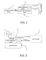
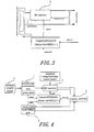
- the portable compound battery unit management system contains a portable high capacity battery unit 1 essentially for supplying a motor drive vehicle with daily requirement of energy consumption for traveling predetermined distance in high energy-weight ratio and reasonable weight and volume.
- the applicable batteries include high power Lithium ion and Lithium polymer batteries.
- exchange type fuel cell used in the notebook computer might be one of the selection owing to its merits in compactness and low cost.
- the portable high power battery unit 1, which is not limited to one unit only in application, can be recharged with an externally adapted battery charger 4.
- the battery unit 1 must be accompanied by a built in battery unit management means 11 with respect to the types of installed battery unit so as to ensure its stability and security in case it is separated from the vehicle.
- Such an independently operable case battery unit management means 11 can liberate difficulty of overall system management and lower the overall cost for electronic control and improve the stability of the overall system.
- the battery unit management means 11 is functional for low capacity indication and low capacity cut-off so as to facilitate means for controlling a DC converter installed at its rear side.
- a main power battery unit 2 is a high power battery unit capable of supplying electrical power to a motor controller 5 for either instantaneously or a long duration of time.
- the applicable batteries for this battery unit are those ordinary batteries such as Pb./CaSO4 battery, Ni-mH battery, Ni-Zn battery, Li-Mn/Li-Co Battery, and Li-Polymer battery. Being an essential power source for the motor, the component batteries used in the main power battery unit are connected in series.
- the battery unit 2 must contain a battery management means 21 or a device for control maximum output current so as to insure the security and stability of the battery unit 2 during operation and prolong the lifespan of the battery unit 2 as well.
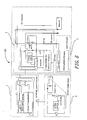
- the battery management means 21 serves to provide the converter 3 and the motor controller 5 installed at the rear side with necessary information for operation.
- the converter 3 is a simple battery charger usable to transfer the electrical energy from the portable high capacity battery unit 1 to the main power battery unit 2 either by boosting up or bucking down the voltage depending on the difference of rated voltages between the portable high capacity battery unit 1 and the main power battery unit 2.
- the mission of the converter 3 is transforming the electric output of the battery unit 1 to the electrical power of the battery unit 2, or transforming the electric output of the battery unit 1 to the working power of the motor controller 5. Since the conventional converter 3 is easy to achieve the object to output maximum current and maximum voltage, the demand of charging and discharging the battery units stably with high efficiency can be easily fulfilled. As the converter 3 is also a battery charger capable of limiting maximum current, it can output power to the moving vehicle so as to assist the main power battery unit 2 by sharing part of power demand for the motor controller 5 and supplement the power to the main power battery unit 2.
- the traveling distance exceeds 30km, which being beyond the ability of the battery unit 1 to carry out, it can be recharged again with the external battery charger 4 for supplement of energy, or prepare two portable high capacity battery units 1, or recharge the entire compound battery system directly thereby completely restoring the power of the main power battery unit 2.
- the portable compound battery management system 100 is designed basically as a battery unit for a light type motor-driven bicycle.
- the performance data are as follows: load: 70kgw, total weight of the vehicle: 130kgw, maximum traveling distance: 70km, traveling distance for fully charged portable high capacity battery unit 1: 35km, average vehicle speed: 30km/hr. Under this situation, a 36v/17Ah/20kg Pb-acid battery unit with a charge indicator is selected relevant to serve as the main power battery unit 2.
- the selective portable high capacity battery unit 1 is a 12 series/10Ah/5kg Lithium-Polymer battery unit accompanied with functions of individual battery voltage control, passive battery capacity balancing, working temperature protection, and battery capacity indication so as to form a battery management means.
- the converter 3 is rated at 5A constant current, 43.5v buck down converter together with a control circuit to work at a predetermined condition.
- the portable high capacity battery unit 1 having 450Wh total power with available power of 430W after stepping down by the converter can provide the light type motor drive auto bicycle to travel 1.2hr and above at a speed of 30km/hr. With this performance, the user can constantly maintain the two battery units 1 and 2 at a fully charged state by means of the office or the domestic outlet as a charging source.
- the overall compound battery management system 100 is able to provide electric energy of 1000Wh for the motor bicycle to run above 3 hours at 30km/h, reaching 90km distance.
- the portable high capacity battery unit 1 may be set in the compound battery management system 100 so as to recharge the overall battery units 1, 2 at the same time, or may select to recharge the portable high capacity battery unit 1 several times alone so as to keep its maximum continuous power output at 1.0kW.
- the compound battery management system can satisfy the demand of the user with low operation cost by effective cooperative action between a high capacity battery unit and a high power output battery unit. This is the kernel of the present invention.
- the battery management means built in the portable high capacity battery unit 1 and the low cost external battery charger 4 usable for charging the Lithium battery with constant current and voltage are already sufficient for maintaining the performance of the high capacity battery unit 1.
- the motor controller 5 installed at the rear terminal of this system is able to work stably only if it can be fulfilled the requirement of maximum continuous input current at minimum 30V working voltage.
- the electronic circuit which is the heart of the system, is but a buck down converter capable of outputting maximum voltage and current. In case the control chip of the circuit has a function to standby at low current, and a simple logic to judge whether the electric power of the two battery units is enough to operate the motor controller (does the vehicle can start?), the both battery unit management means are sure to operate the both battery units stably. If the portable compound battery unit management system of this invention is compared with the above two cited inventions and other prior arts, it has several noteworthy advantages, namely:
- the present invention is a high level technical creation and by no means, simply utilizing conventional technology or knowledge known prior to the application for patent or can easily made by persons skilled in the arts prior to the application for patent, the invention has neither been published or put to public use, nor displayed in an exhibition. Therefore, we think, the present invention is entitled for patent.
Landscapes
- Engineering & Computer Science (AREA)
- Power Engineering (AREA)
- Electric Propulsion And Braking For Vehicles (AREA)
- Charge And Discharge Circuits For Batteries Or The Like (AREA)
- Secondary Cells (AREA)
Applications Claiming Priority (1)
| Application Number | Priority Date | Filing Date | Title |
|---|---|---|---|
| CNB2005100071385A CN100364203C (zh) | 2005-01-21 | 2005-01-21 | 可携式复合型电池管理系统 |
Publications (3)
| Publication Number | Publication Date |
|---|---|
| EP1684397A2 true EP1684397A2 (de) | 2006-07-26 |
| EP1684397A3 EP1684397A3 (de) | 2009-01-07 |
| EP1684397B1 EP1684397B1 (de) | 2011-10-05 |
Family
ID=34875263
Family Applications (1)
| Application Number | Title | Priority Date | Filing Date |
|---|---|---|---|
| EP06000508A Expired - Lifetime EP1684397B1 (de) | 2005-01-21 | 2006-01-11 | Verwaltungssystem für tragbare Verbindungsbatterie-Einheit |
Country Status (4)
| Country | Link |
|---|---|
| EP (1) | EP1684397B1 (de) |
| CN (1) | CN100364203C (de) |
| AT (1) | ATE527737T1 (de) |
| ES (1) | ES2374958T3 (de) |
Cited By (37)
| Publication number | Priority date | Publication date | Assignee | Title |
|---|---|---|---|---|
| CN101964605A (zh) * | 2010-08-05 | 2011-02-02 | 苏州柔印光电科技有限公司 | 一种太阳能野外应急电源 |
| US8648571B2 (en) | 2007-03-06 | 2014-02-11 | Toyota Jidosha Kabushiki Kaisha | Electric-powered vehicle, method for estimating state of charge, and computer-readable storage medium having program stored therein for causing computer to execute method for estimating state of charge |
| JP2015094742A (ja) * | 2013-11-14 | 2015-05-18 | ルネサスエレクトロニクス株式会社 | 半導体装置、電池パック及び携帯端末 |
| US9346366B2 (en) | 2012-08-29 | 2016-05-24 | Mitsubishi Electric Corporation | Charge/discharge system |
| US11309832B2 (en) | 2006-12-06 | 2022-04-19 | Solaredge Technologies Ltd. | Distributed power harvesting systems using DC power sources |
| CN114454735A (zh) * | 2022-01-18 | 2022-05-10 | 绿水青山(辽宁)电力设计院有限公司 | 一种具有离网充电功能的电动汽车 |
| US11349432B2 (en) | 2010-11-09 | 2022-05-31 | Solaredge Technologies Ltd. | Arc detection and prevention in a power generation system |
| US11424616B2 (en) | 2008-05-05 | 2022-08-23 | Solaredge Technologies Ltd. | Direct current power combiner |
| US11476799B2 (en) | 2006-12-06 | 2022-10-18 | Solaredge Technologies Ltd. | Distributed power harvesting systems using DC power sources |
| US11489330B2 (en) | 2010-11-09 | 2022-11-01 | Solaredge Technologies Ltd. | Arc detection and prevention in a power generation system |
| US11569660B2 (en) | 2006-12-06 | 2023-01-31 | Solaredge Technologies Ltd. | Distributed power harvesting systems using DC power sources |
| US11569659B2 (en) | 2006-12-06 | 2023-01-31 | Solaredge Technologies Ltd. | Distributed power harvesting systems using DC power sources |
| US11579235B2 (en) | 2006-12-06 | 2023-02-14 | Solaredge Technologies Ltd. | Safety mechanisms, wake up and shutdown methods in distributed power installations |
| US11594968B2 (en) | 2007-08-06 | 2023-02-28 | Solaredge Technologies Ltd. | Digital average input current control in power converter |
| US11598652B2 (en) | 2006-12-06 | 2023-03-07 | Solaredge Technologies Ltd. | Monitoring of distributed power harvesting systems using DC power sources |
| US11620885B2 (en) | 2012-01-30 | 2023-04-04 | Solaredge Technologies Ltd. | Photovoltaic panel circuitry |
| US11682918B2 (en) | 2006-12-06 | 2023-06-20 | Solaredge Technologies Ltd. | Battery power delivery module |
| US11687112B2 (en) | 2006-12-06 | 2023-06-27 | Solaredge Technologies Ltd. | Distributed power harvesting systems using DC power sources |
| US11728768B2 (en) | 2006-12-06 | 2023-08-15 | Solaredge Technologies Ltd. | Pairing of components in a direct current distributed power generation system |
| US11735910B2 (en) | 2006-12-06 | 2023-08-22 | Solaredge Technologies Ltd. | Distributed power system using direct current power sources |
| US11855231B2 (en) | 2006-12-06 | 2023-12-26 | Solaredge Technologies Ltd. | Distributed power harvesting systems using DC power sources |
| US11870250B2 (en) | 2016-04-05 | 2024-01-09 | Solaredge Technologies Ltd. | Chain of power devices |
| US11867729B2 (en) | 2009-05-26 | 2024-01-09 | Solaredge Technologies Ltd. | Theft detection and prevention in a power generation system |
| US11888387B2 (en) | 2006-12-06 | 2024-01-30 | Solaredge Technologies Ltd. | Safety mechanisms, wake up and shutdown methods in distributed power installations |
| US11929620B2 (en) | 2012-01-30 | 2024-03-12 | Solaredge Technologies Ltd. | Maximizing power in a photovoltaic distributed power system |
| US11962243B2 (en) | 2006-12-06 | 2024-04-16 | Solaredge Technologies Ltd. | Method for distributed power harvesting using DC power sources |
| US11979037B2 (en) | 2012-01-11 | 2024-05-07 | Solaredge Technologies Ltd. | Photovoltaic module |
| US12003107B2 (en) | 2013-03-14 | 2024-06-04 | Solaredge Technologies Ltd. | Method and apparatus for storing and depleting energy |
| US12027849B2 (en) | 2006-12-06 | 2024-07-02 | Solaredge Technologies Ltd. | Distributed power system using direct current power sources |
| US12057807B2 (en) | 2016-04-05 | 2024-08-06 | Solaredge Technologies Ltd. | Chain of power devices |
| US12068599B2 (en) | 2006-12-06 | 2024-08-20 | Solaredge Technologies Ltd. | System and method for protection during inverter shutdown in distributed power installations |
| US12191668B2 (en) | 2012-01-30 | 2025-01-07 | Solaredge Technologies Ltd. | Maximizing power in a photovoltaic distributed power system |
| US12218505B2 (en) | 2011-01-12 | 2025-02-04 | Solaredge Technologies Ltd. | Serially connected inverters |
| US12348182B2 (en) | 2016-04-05 | 2025-07-01 | Solaredge Technologies Ltd. | Safety switch for photovoltaic systems |
| US12418177B2 (en) | 2009-10-24 | 2025-09-16 | Solaredge Technologies Ltd. | Distributed power system using direct current power sources |
| US12665546B2 (en) | 2011-01-28 | 2026-06-23 | Solaredge Technologies Ltd. | Pairing of components in a direct current distributed power generation system |
| US12676488B2 (en) | 2006-12-06 | 2026-07-07 | Solaredge Technologies Ltd. | System and method for protection during inverter shutdown in distributed power installations |
Families Citing this family (9)
| Publication number | Priority date | Publication date | Assignee | Title |
|---|---|---|---|---|
| CN102074983A (zh) * | 2010-11-29 | 2011-05-25 | 周荻 | 锂动力电动助力车电气部分的设计 |
| GB2511712B (en) * | 2011-12-02 | 2016-08-17 | Dcbpower Inc | Electrically rechargeabe, dual chemistry, battery system for use in plug-in or hybrid electric vehicles |
| US9522599B2 (en) * | 2012-03-19 | 2016-12-20 | GM Global Technology Operations LLC | Method for estimating parameters for a vehicle battery |
| DE102012217193B4 (de) | 2012-09-24 | 2025-03-27 | Bayerische Motoren Werke Aktiengesellschaft | Verfahren und Vorrichtung zum Betreiben eines Bordnetzes |
| TWI532294B (zh) * | 2014-01-09 | 2016-05-01 | 法拉蒂綠能股份有限公司 | Portable compound battery system |
| CN107650659A (zh) * | 2017-08-09 | 2018-02-02 | 浙江吉利新能源商用车有限公司 | 一种用于车辆的动力电池系统 |
| CN107650707B (zh) * | 2017-09-12 | 2019-11-19 | 纳恩博(北京)科技有限公司 | 一种充电桩 |
| CN108859829A (zh) * | 2018-07-25 | 2018-11-23 | 朱娟娟 | 一种新能源汽车供电装置及备用充电电池管理系统 |
| CN114498884A (zh) * | 2022-01-18 | 2022-05-13 | 绿水青山(辽宁)电力设计院有限公司 | 一种具有离网充电功能的电动自行车 |
Citations (3)
| Publication number | Priority date | Publication date | Assignee | Title |
|---|---|---|---|---|
| TW494071B (en) | 1998-10-29 | 2002-07-11 | Ling-Yuan Tzeng | Composite motor vehicle battery |
| WO2002081255A1 (en) | 2001-04-05 | 2002-10-17 | Electrovaya Inc. | Energy storage device for loads having variable power rates |
| TW559602B (en) | 2001-10-09 | 2003-11-01 | Ind Tech Res Inst | Electric power output control system of compound type fuel-cell electric vehicle |
Family Cites Families (8)
| Publication number | Priority date | Publication date | Assignee | Title |
|---|---|---|---|---|
| JP3493906B2 (ja) * | 1996-07-04 | 2004-02-03 | 松下電器産業株式会社 | 電気自転車 |
| CN2344267Y (zh) * | 1998-06-10 | 1999-10-20 | 南京通用电力车船有限公司 | 续航能力强的电动自行车 |
| US6331365B1 (en) * | 1998-11-12 | 2001-12-18 | General Electric Company | Traction motor drive system |
| JP2000253591A (ja) * | 1999-03-01 | 2000-09-14 | Tokyo R & D:Kk | 電気自動車 |
| JP3615445B2 (ja) * | 2000-01-31 | 2005-02-02 | 三洋電機株式会社 | ハイブリッドカーの電源装置 |
| US20030105562A1 (en) * | 2001-11-30 | 2003-06-05 | Industrial Technology Research Institute | Power output control system for electric vehicle with hybrid fuel cell |
| DE10318494A1 (de) * | 2003-04-24 | 2004-11-11 | Bayerische Motoren Werke Ag | Energieversorgungssystem für ein Fahrzeug |
| US6989653B2 (en) * | 2003-05-09 | 2006-01-24 | Mitsubishi Denki Kabushiki Kaisha | Battery power circuit and automobile battery power circuit |
-
2005
- 2005-01-21 CN CNB2005100071385A patent/CN100364203C/zh not_active Expired - Lifetime
-
2006
- 2006-01-11 AT AT06000508T patent/ATE527737T1/de not_active IP Right Cessation
- 2006-01-11 ES ES06000508T patent/ES2374958T3/es not_active Expired - Lifetime
- 2006-01-11 EP EP06000508A patent/EP1684397B1/de not_active Expired - Lifetime
Patent Citations (3)
| Publication number | Priority date | Publication date | Assignee | Title |
|---|---|---|---|---|
| TW494071B (en) | 1998-10-29 | 2002-07-11 | Ling-Yuan Tzeng | Composite motor vehicle battery |
| WO2002081255A1 (en) | 2001-04-05 | 2002-10-17 | Electrovaya Inc. | Energy storage device for loads having variable power rates |
| TW559602B (en) | 2001-10-09 | 2003-11-01 | Ind Tech Res Inst | Electric power output control system of compound type fuel-cell electric vehicle |
Cited By (61)
| Publication number | Priority date | Publication date | Assignee | Title |
|---|---|---|---|---|
| US11962243B2 (en) | 2006-12-06 | 2024-04-16 | Solaredge Technologies Ltd. | Method for distributed power harvesting using DC power sources |
| US11594880B2 (en) | 2006-12-06 | 2023-02-28 | Solaredge Technologies Ltd. | Distributed power harvesting systems using DC power sources |
| US12676488B2 (en) | 2006-12-06 | 2026-07-07 | Solaredge Technologies Ltd. | System and method for protection during inverter shutdown in distributed power installations |
| US12388492B2 (en) | 2006-12-06 | 2025-08-12 | Solaredge Technologies Ltd. | Safety mechanisms, wake up and shutdown methods in distributed power installations |
| US11309832B2 (en) | 2006-12-06 | 2022-04-19 | Solaredge Technologies Ltd. | Distributed power harvesting systems using DC power sources |
| US12316274B2 (en) | 2006-12-06 | 2025-05-27 | Solaredge Technologies Ltd. | Pairing of components in a direct current distributed power generation system |
| US12281919B2 (en) | 2006-12-06 | 2025-04-22 | Solaredge Technologies Ltd. | Monitoring of distributed power harvesting systems using DC power sources |
| US12276997B2 (en) | 2006-12-06 | 2025-04-15 | Solaredge Technologies Ltd. | Distributed power harvesting systems using DC power sources |
| US11476799B2 (en) | 2006-12-06 | 2022-10-18 | Solaredge Technologies Ltd. | Distributed power harvesting systems using DC power sources |
| US12224706B2 (en) | 2006-12-06 | 2025-02-11 | Solaredge Technologies Ltd. | Pairing of components in a direct current distributed power generation system |
| US11569660B2 (en) | 2006-12-06 | 2023-01-31 | Solaredge Technologies Ltd. | Distributed power harvesting systems using DC power sources |
| US11569659B2 (en) | 2006-12-06 | 2023-01-31 | Solaredge Technologies Ltd. | Distributed power harvesting systems using DC power sources |
| US11575261B2 (en) | 2006-12-06 | 2023-02-07 | Solaredge Technologies Ltd. | Distributed power harvesting systems using DC power sources |
| US11575260B2 (en) | 2006-12-06 | 2023-02-07 | Solaredge Technologies Ltd. | Distributed power harvesting systems using DC power sources |
| US11579235B2 (en) | 2006-12-06 | 2023-02-14 | Solaredge Technologies Ltd. | Safety mechanisms, wake up and shutdown methods in distributed power installations |
| US11888387B2 (en) | 2006-12-06 | 2024-01-30 | Solaredge Technologies Ltd. | Safety mechanisms, wake up and shutdown methods in distributed power installations |
| US11594882B2 (en) | 2006-12-06 | 2023-02-28 | Solaredge Technologies Ltd. | Distributed power harvesting systems using DC power sources |
| US11594881B2 (en) | 2006-12-06 | 2023-02-28 | Solaredge Technologies Ltd. | Distributed power harvesting systems using DC power sources |
| US12107417B2 (en) | 2006-12-06 | 2024-10-01 | Solaredge Technologies Ltd. | Distributed power harvesting systems using DC power sources |
| US11598652B2 (en) | 2006-12-06 | 2023-03-07 | Solaredge Technologies Ltd. | Monitoring of distributed power harvesting systems using DC power sources |
| US12068599B2 (en) | 2006-12-06 | 2024-08-20 | Solaredge Technologies Ltd. | System and method for protection during inverter shutdown in distributed power installations |
| US11658482B2 (en) | 2006-12-06 | 2023-05-23 | Solaredge Technologies Ltd. | Distributed power harvesting systems using DC power sources |
| US11682918B2 (en) | 2006-12-06 | 2023-06-20 | Solaredge Technologies Ltd. | Battery power delivery module |
| US11687112B2 (en) | 2006-12-06 | 2023-06-27 | Solaredge Technologies Ltd. | Distributed power harvesting systems using DC power sources |
| US11728768B2 (en) | 2006-12-06 | 2023-08-15 | Solaredge Technologies Ltd. | Pairing of components in a direct current distributed power generation system |
| US11735910B2 (en) | 2006-12-06 | 2023-08-22 | Solaredge Technologies Ltd. | Distributed power system using direct current power sources |
| US11855231B2 (en) | 2006-12-06 | 2023-12-26 | Solaredge Technologies Ltd. | Distributed power harvesting systems using DC power sources |
| US12046940B2 (en) | 2006-12-06 | 2024-07-23 | Solaredge Technologies Ltd. | Battery power control |
| US12032080B2 (en) | 2006-12-06 | 2024-07-09 | Solaredge Technologies Ltd. | Safety mechanisms, wake up and shutdown methods in distributed power installations |
| US11961922B2 (en) | 2006-12-06 | 2024-04-16 | Solaredge Technologies Ltd. | Distributed power harvesting systems using DC power sources |
| US12027849B2 (en) | 2006-12-06 | 2024-07-02 | Solaredge Technologies Ltd. | Distributed power system using direct current power sources |
| US12027970B2 (en) | 2006-12-06 | 2024-07-02 | Solaredge Technologies Ltd. | Safety mechanisms, wake up and shutdown methods in distributed power installations |
| US8648571B2 (en) | 2007-03-06 | 2014-02-11 | Toyota Jidosha Kabushiki Kaisha | Electric-powered vehicle, method for estimating state of charge, and computer-readable storage medium having program stored therein for causing computer to execute method for estimating state of charge |
| US11594968B2 (en) | 2007-08-06 | 2023-02-28 | Solaredge Technologies Ltd. | Digital average input current control in power converter |
| US11424616B2 (en) | 2008-05-05 | 2022-08-23 | Solaredge Technologies Ltd. | Direct current power combiner |
| US12218498B2 (en) | 2008-05-05 | 2025-02-04 | Solaredge Technologies Ltd. | Direct current power combiner |
| US12306215B2 (en) | 2009-05-26 | 2025-05-20 | Solaredge Technologies Ltd. | Theft detection and prevention in a power generation system |
| US11867729B2 (en) | 2009-05-26 | 2024-01-09 | Solaredge Technologies Ltd. | Theft detection and prevention in a power generation system |
| US12418177B2 (en) | 2009-10-24 | 2025-09-16 | Solaredge Technologies Ltd. | Distributed power system using direct current power sources |
| CN101964605A (zh) * | 2010-08-05 | 2011-02-02 | 苏州柔印光电科技有限公司 | 一种太阳能野外应急电源 |
| US11489330B2 (en) | 2010-11-09 | 2022-11-01 | Solaredge Technologies Ltd. | Arc detection and prevention in a power generation system |
| US11349432B2 (en) | 2010-11-09 | 2022-05-31 | Solaredge Technologies Ltd. | Arc detection and prevention in a power generation system |
| US12003215B2 (en) | 2010-11-09 | 2024-06-04 | Solaredge Technologies Ltd. | Arc detection and prevention in a power generation system |
| US12407158B2 (en) | 2010-11-09 | 2025-09-02 | Solaredge Technologies Ltd. | Arc detection and prevention in a power generation system |
| US12218505B2 (en) | 2011-01-12 | 2025-02-04 | Solaredge Technologies Ltd. | Serially connected inverters |
| US12665546B2 (en) | 2011-01-28 | 2026-06-23 | Solaredge Technologies Ltd. | Pairing of components in a direct current distributed power generation system |
| US11979037B2 (en) | 2012-01-11 | 2024-05-07 | Solaredge Technologies Ltd. | Photovoltaic module |
| US11929620B2 (en) | 2012-01-30 | 2024-03-12 | Solaredge Technologies Ltd. | Maximizing power in a photovoltaic distributed power system |
| US12191668B2 (en) | 2012-01-30 | 2025-01-07 | Solaredge Technologies Ltd. | Maximizing power in a photovoltaic distributed power system |
| US12094306B2 (en) | 2012-01-30 | 2024-09-17 | Solaredge Technologies Ltd. | Photovoltaic panel circuitry |
| US11620885B2 (en) | 2012-01-30 | 2023-04-04 | Solaredge Technologies Ltd. | Photovoltaic panel circuitry |
| US12633754B2 (en) | 2012-01-30 | 2026-05-19 | Solaredge Technologies Ltd. | Maximizing power in a photovoltaic distributed power system |
| US9346366B2 (en) | 2012-08-29 | 2016-05-24 | Mitsubishi Electric Corporation | Charge/discharge system |
| US12255457B2 (en) | 2013-03-14 | 2025-03-18 | Solaredge Technologies Ltd. | Method and apparatus for storing and depleting energy |
| US12003107B2 (en) | 2013-03-14 | 2024-06-04 | Solaredge Technologies Ltd. | Method and apparatus for storing and depleting energy |
| JP2015094742A (ja) * | 2013-11-14 | 2015-05-18 | ルネサスエレクトロニクス株式会社 | 半導体装置、電池パック及び携帯端末 |
| US12348182B2 (en) | 2016-04-05 | 2025-07-01 | Solaredge Technologies Ltd. | Safety switch for photovoltaic systems |
| US12057807B2 (en) | 2016-04-05 | 2024-08-06 | Solaredge Technologies Ltd. | Chain of power devices |
| US12627140B2 (en) | 2016-04-05 | 2026-05-12 | Solaredge Technologies Ltd. | Chain of power devices |
| US11870250B2 (en) | 2016-04-05 | 2024-01-09 | Solaredge Technologies Ltd. | Chain of power devices |
| CN114454735A (zh) * | 2022-01-18 | 2022-05-10 | 绿水青山(辽宁)电力设计院有限公司 | 一种具有离网充电功能的电动汽车 |
Also Published As
| Publication number | Publication date |
|---|---|
| CN1652426A (zh) | 2005-08-10 |
| ATE527737T1 (de) | 2011-10-15 |
| CN100364203C (zh) | 2008-01-23 |
| EP1684397B1 (de) | 2011-10-05 |
| EP1684397A3 (de) | 2009-01-07 |
| ES2374958T3 (es) | 2012-02-23 |
Similar Documents
| Publication | Publication Date | Title |
|---|---|---|
| EP1684397B1 (de) | Verwaltungssystem für tragbare Verbindungsbatterie-Einheit | |
| CA2538299C (en) | Energy storage device for loads having variable power consumption | |
| US7825615B2 (en) | Intelligent motorized appliances with multiple power sources | |
| US20090317696A1 (en) | Compound battery device having lithium battery and lead-acid battery | |
| US7148637B2 (en) | Portable compound battery unit management system | |
| US20050057215A1 (en) | Systems and methods for charging a battery | |
| TWI532294B (zh) | Portable compound battery system | |
| JP2004530398A (ja) | 可変電力量を有する負荷用エネルギ貯蔵装置 | |
| TW200401465A (en) | Cordless device system | |
| JPH09121461A (ja) | 自己充電型電池およびそれを用いた電気用品 | |
| JP2008048473A (ja) | 充電器 | |
| US20070080663A1 (en) | Portable charger with a rechargeable back-up battery | |
| US20180233929A1 (en) | Battery to battery charger using asymmetric batteries | |
| CN113071368B (zh) | 一种增加续航里程的12v电池系统 | |
| CN201039040Y (zh) | 野外光伏供电系统 | |
| RU53818U1 (ru) | Батарея электрических накопителей энергии | |
| JP4564940B2 (ja) | 電子機器並びに該電子機器に用いられる電池パック及び負荷装置 | |
| WO2005034303A1 (en) | Portable charger having built-in secondary lithium battery | |
| CA2428403A1 (en) | Energy storage device for loads having variable power rates | |
| JP3091637U (ja) | 携帯電話用補助充電器 | |
| CN2935483Y (zh) | 便携式数码设备的外置电池包 | |
| JP2006223026A (ja) | ポータブル複合型電池の管理システム | |
| CN1747277A (zh) | 太阳能移动电源 | |
| CN220382775U (zh) | 一种自移动式供电设备及系统 | |
| TWI259816B (en) | Portable compound battery management system |
Legal Events
| Date | Code | Title | Description |
|---|---|---|---|
| PUAI | Public reference made under article 153(3) epc to a published international application that has entered the european phase |
Free format text: ORIGINAL CODE: 0009012 |
|
| AK | Designated contracting states |
Kind code of ref document: A2 Designated state(s): AT BE BG CH CY CZ DE DK EE ES FI FR GB GR HU IE IS IT LI LT LU LV MC NL PL PT RO SE SI SK TR |
|
| AX | Request for extension of the european patent |
Extension state: AL BA HR MK YU |
|
| PUAL | Search report despatched |
Free format text: ORIGINAL CODE: 0009013 |
|
| AK | Designated contracting states |
Kind code of ref document: A3 Designated state(s): AT BE BG CH CY CZ DE DK EE ES FI FR GB GR HU IE IS IT LI LT LU LV MC NL PL PT RO SE SI SK TR |
|
| AX | Request for extension of the european patent |
Extension state: AL BA HR MK YU |
|
| 17P | Request for examination filed |
Effective date: 20090619 |
|
| AKX | Designation fees paid |
Designated state(s): AT BE BG CH CY CZ DE DK EE ES FI FR GB GR HU IE IS IT LI LT LU LV MC NL PL PT RO SE SI SK TR |
|
| 17Q | First examination report despatched |
Effective date: 20090901 |
|
| GRAP | Despatch of communication of intention to grant a patent |
Free format text: ORIGINAL CODE: EPIDOSNIGR1 |
|
| GRAS | Grant fee paid |
Free format text: ORIGINAL CODE: EPIDOSNIGR3 |
|
| GRAA | (expected) grant |
Free format text: ORIGINAL CODE: 0009210 |
|
| AK | Designated contracting states |
Kind code of ref document: B1 Designated state(s): AT BE BG CH CY CZ DE DK EE ES FI FR GB GR HU IE IS IT LI LT LU LV MC NL PL PT RO SE SI SK TR |
|
| REG | Reference to a national code |
Ref country code: GB Ref legal event code: FG4D |
|
| REG | Reference to a national code |
Ref country code: DE Ref legal event code: R081 Ref document number: 602006024778 Country of ref document: DE Owner name: MA, BIN-YEN, TW Free format text: FORMER OWNER: WIZ ENERGY TECHNOLOGY CO., LTD., JHONGSHAN TAIPEI CITY, TW |
|
| REG | Reference to a national code |
Ref country code: CH Ref legal event code: EP |
|
| REG | Reference to a national code |
Ref country code: IE Ref legal event code: FG4D |
|
| REG | Reference to a national code |
Ref country code: DE Ref legal event code: R096 Ref document number: 602006024778 Country of ref document: DE Effective date: 20111208 |
|
| REG | Reference to a national code |
Ref country code: NL Ref legal event code: T3 |
|
| REG | Reference to a national code |
Ref country code: ES Ref legal event code: FG2A Ref document number: 2374958 Country of ref document: ES Kind code of ref document: T3 Effective date: 20120223 |
|
| PG25 | Lapsed in a contracting state [announced via postgrant information from national office to epo] |
Ref country code: SI Free format text: LAPSE BECAUSE OF FAILURE TO SUBMIT A TRANSLATION OF THE DESCRIPTION OR TO PAY THE FEE WITHIN THE PRESCRIBED TIME-LIMIT Effective date: 20111005 |
|
| LTIE | Lt: invalidation of european patent or patent extension |
Effective date: 20111005 |
|
| REG | Reference to a national code |
Ref country code: AT Ref legal event code: MK05 Ref document number: 527737 Country of ref document: AT Kind code of ref document: T Effective date: 20111005 |
|
| PG25 | Lapsed in a contracting state [announced via postgrant information from national office to epo] |
Ref country code: LT Free format text: LAPSE BECAUSE OF FAILURE TO SUBMIT A TRANSLATION OF THE DESCRIPTION OR TO PAY THE FEE WITHIN THE PRESCRIBED TIME-LIMIT Effective date: 20111005 Ref country code: BE Free format text: LAPSE BECAUSE OF FAILURE TO SUBMIT A TRANSLATION OF THE DESCRIPTION OR TO PAY THE FEE WITHIN THE PRESCRIBED TIME-LIMIT Effective date: 20111005 Ref country code: IS Free format text: LAPSE BECAUSE OF FAILURE TO SUBMIT A TRANSLATION OF THE DESCRIPTION OR TO PAY THE FEE WITHIN THE PRESCRIBED TIME-LIMIT Effective date: 20120205 |
|
| PG25 | Lapsed in a contracting state [announced via postgrant information from national office to epo] |
Ref country code: GR Free format text: LAPSE BECAUSE OF FAILURE TO SUBMIT A TRANSLATION OF THE DESCRIPTION OR TO PAY THE FEE WITHIN THE PRESCRIBED TIME-LIMIT Effective date: 20120106 Ref country code: SE Free format text: LAPSE BECAUSE OF FAILURE TO SUBMIT A TRANSLATION OF THE DESCRIPTION OR TO PAY THE FEE WITHIN THE PRESCRIBED TIME-LIMIT Effective date: 20111005 Ref country code: PT Free format text: LAPSE BECAUSE OF FAILURE TO SUBMIT A TRANSLATION OF THE DESCRIPTION OR TO PAY THE FEE WITHIN THE PRESCRIBED TIME-LIMIT Effective date: 20120206 Ref country code: LV Free format text: LAPSE BECAUSE OF FAILURE TO SUBMIT A TRANSLATION OF THE DESCRIPTION OR TO PAY THE FEE WITHIN THE PRESCRIBED TIME-LIMIT Effective date: 20111005 |
|
| PG25 | Lapsed in a contracting state [announced via postgrant information from national office to epo] |
Ref country code: CY Free format text: LAPSE BECAUSE OF FAILURE TO SUBMIT A TRANSLATION OF THE DESCRIPTION OR TO PAY THE FEE WITHIN THE PRESCRIBED TIME-LIMIT Effective date: 20111005 |
|
| PG25 | Lapsed in a contracting state [announced via postgrant information from national office to epo] |
Ref country code: BG Free format text: LAPSE BECAUSE OF FAILURE TO SUBMIT A TRANSLATION OF THE DESCRIPTION OR TO PAY THE FEE WITHIN THE PRESCRIBED TIME-LIMIT Effective date: 20120105 Ref country code: SK Free format text: LAPSE BECAUSE OF FAILURE TO SUBMIT A TRANSLATION OF THE DESCRIPTION OR TO PAY THE FEE WITHIN THE PRESCRIBED TIME-LIMIT Effective date: 20111005 Ref country code: EE Free format text: LAPSE BECAUSE OF FAILURE TO SUBMIT A TRANSLATION OF THE DESCRIPTION OR TO PAY THE FEE WITHIN THE PRESCRIBED TIME-LIMIT Effective date: 20111005 Ref country code: DK Free format text: LAPSE BECAUSE OF FAILURE TO SUBMIT A TRANSLATION OF THE DESCRIPTION OR TO PAY THE FEE WITHIN THE PRESCRIBED TIME-LIMIT Effective date: 20111005 Ref country code: CZ Free format text: LAPSE BECAUSE OF FAILURE TO SUBMIT A TRANSLATION OF THE DESCRIPTION OR TO PAY THE FEE WITHIN THE PRESCRIBED TIME-LIMIT Effective date: 20111005 |
|
| PLBE | No opposition filed within time limit |
Free format text: ORIGINAL CODE: 0009261 |
|
| STAA | Information on the status of an ep patent application or granted ep patent |
Free format text: STATUS: NO OPPOSITION FILED WITHIN TIME LIMIT |
|
| PG25 | Lapsed in a contracting state [announced via postgrant information from national office to epo] |
Ref country code: PL Free format text: LAPSE BECAUSE OF FAILURE TO SUBMIT A TRANSLATION OF THE DESCRIPTION OR TO PAY THE FEE WITHIN THE PRESCRIBED TIME-LIMIT Effective date: 20111005 Ref country code: RO Free format text: LAPSE BECAUSE OF FAILURE TO SUBMIT A TRANSLATION OF THE DESCRIPTION OR TO PAY THE FEE WITHIN THE PRESCRIBED TIME-LIMIT Effective date: 20111005 Ref country code: MC Free format text: LAPSE BECAUSE OF NON-PAYMENT OF DUE FEES Effective date: 20120131 |
|
| REG | Reference to a national code |
Ref country code: CH Ref legal event code: PL |
|
| 26N | No opposition filed |
Effective date: 20120706 |
|
| REG | Reference to a national code |
Ref country code: IE Ref legal event code: MM4A |
|
| PG25 | Lapsed in a contracting state [announced via postgrant information from national office to epo] |
Ref country code: CH Free format text: LAPSE BECAUSE OF NON-PAYMENT OF DUE FEES Effective date: 20120131 Ref country code: LI Free format text: LAPSE BECAUSE OF NON-PAYMENT OF DUE FEES Effective date: 20120131 |
|
| REG | Reference to a national code |
Ref country code: DE Ref legal event code: R097 Ref document number: 602006024778 Country of ref document: DE Effective date: 20120706 |
|
| PG25 | Lapsed in a contracting state [announced via postgrant information from national office to epo] |
Ref country code: IE Free format text: LAPSE BECAUSE OF NON-PAYMENT OF DUE FEES Effective date: 20120111 Ref country code: AT Free format text: LAPSE BECAUSE OF FAILURE TO SUBMIT A TRANSLATION OF THE DESCRIPTION OR TO PAY THE FEE WITHIN THE PRESCRIBED TIME-LIMIT Effective date: 20111005 |
|
| PG25 | Lapsed in a contracting state [announced via postgrant information from national office to epo] |
Ref country code: FI Free format text: LAPSE BECAUSE OF FAILURE TO SUBMIT A TRANSLATION OF THE DESCRIPTION OR TO PAY THE FEE WITHIN THE PRESCRIBED TIME-LIMIT Effective date: 20111005 |
|
| PGFP | Annual fee paid to national office [announced via postgrant information from national office to epo] |
Ref country code: GB Payment date: 20131121 Year of fee payment: 9 |
|
| PGFP | Annual fee paid to national office [announced via postgrant information from national office to epo] |
Ref country code: NL Payment date: 20140116 Year of fee payment: 9 |
|
| PG25 | Lapsed in a contracting state [announced via postgrant information from national office to epo] |
Ref country code: LU Free format text: LAPSE BECAUSE OF NON-PAYMENT OF DUE FEES Effective date: 20120111 |
|
| PG25 | Lapsed in a contracting state [announced via postgrant information from national office to epo] |
Ref country code: HU Free format text: LAPSE BECAUSE OF FAILURE TO SUBMIT A TRANSLATION OF THE DESCRIPTION OR TO PAY THE FEE WITHIN THE PRESCRIBED TIME-LIMIT Effective date: 20060111 |
|
| REG | Reference to a national code |
Ref country code: DE Ref legal event code: R082 Ref document number: 602006024778 Country of ref document: DE Representative=s name: WITTMANN HERNANDEZ PATENTANWAELTE PARTNERSCHAF, DE Ref country code: DE Ref legal event code: R081 Ref document number: 602006024778 Country of ref document: DE Owner name: MA, BIN-YEN, TW Free format text: FORMER OWNER: WIZ ENERGY TECHNOLOGY CO., LTD., JHONGSHAN TAIPEI CITY, TW Ref country code: DE Ref legal event code: R082 Ref document number: 602006024778 Country of ref document: DE Representative=s name: WITTMANN, GUENTHER, DIPL.-ING. UNIV., DE |
|
| REG | Reference to a national code |
Ref country code: NL Ref legal event code: V1 Effective date: 20150801 |
|
| REG | Reference to a national code |
Ref country code: ES Ref legal event code: PC2A Owner name: MA, BIN-YEN Effective date: 20150810 |
|
| GBPC | Gb: european patent ceased through non-payment of renewal fee |
Effective date: 20150111 |
|
| PG25 | Lapsed in a contracting state [announced via postgrant information from national office to epo] |
Ref country code: NL Free format text: LAPSE BECAUSE OF NON-PAYMENT OF DUE FEES Effective date: 20150801 |
|
| REG | Reference to a national code |
Ref country code: FR Ref legal event code: TP Owner name: BIN-YEN MA, CN Effective date: 20150908 |
|
| PG25 | Lapsed in a contracting state [announced via postgrant information from national office to epo] |
Ref country code: GB Free format text: LAPSE BECAUSE OF NON-PAYMENT OF DUE FEES Effective date: 20150111 |
|
| REG | Reference to a national code |
Ref country code: FR Ref legal event code: PLFP Year of fee payment: 11 |
|
| REG | Reference to a national code |
Ref country code: DE Ref legal event code: R082 Ref document number: 602006024778 Country of ref document: DE Representative=s name: WITTMANN, GUENTHER, DIPL.-ING. UNIV., DE |
|
| REG | Reference to a national code |
Ref country code: FR Ref legal event code: PLFP Year of fee payment: 12 |
|
| REG | Reference to a national code |
Ref country code: FR Ref legal event code: PLFP Year of fee payment: 13 |
|
| PGFP | Annual fee paid to national office [announced via postgrant information from national office to epo] |
Ref country code: DE Payment date: 20220131 Year of fee payment: 17 |
|
| PGFP | Annual fee paid to national office [announced via postgrant information from national office to epo] |
Ref country code: TR Payment date: 20220111 Year of fee payment: 17 Ref country code: IT Payment date: 20220120 Year of fee payment: 17 Ref country code: FR Payment date: 20220128 Year of fee payment: 17 Ref country code: ES Payment date: 20220201 Year of fee payment: 17 |
|
| REG | Reference to a national code |
Ref country code: DE Ref legal event code: R119 Ref document number: 602006024778 Country of ref document: DE |
|
| PG25 | Lapsed in a contracting state [announced via postgrant information from national office to epo] |
Ref country code: DE Free format text: LAPSE BECAUSE OF NON-PAYMENT OF DUE FEES Effective date: 20230801 |
|
| PG25 | Lapsed in a contracting state [announced via postgrant information from national office to epo] |
Ref country code: FR Free format text: LAPSE BECAUSE OF NON-PAYMENT OF DUE FEES Effective date: 20230131 |
|
| PG25 | Lapsed in a contracting state [announced via postgrant information from national office to epo] |
Ref country code: IT Free format text: LAPSE BECAUSE OF NON-PAYMENT OF DUE FEES Effective date: 20230111 |
|
| REG | Reference to a national code |
Ref country code: ES Ref legal event code: FD2A Effective date: 20240327 |
|
| PG25 | Lapsed in a contracting state [announced via postgrant information from national office to epo] |
Ref country code: ES Free format text: LAPSE BECAUSE OF NON-PAYMENT OF DUE FEES Effective date: 20230112 |
|
| PG25 | Lapsed in a contracting state [announced via postgrant information from national office to epo] |
Ref country code: ES Free format text: LAPSE BECAUSE OF NON-PAYMENT OF DUE FEES Effective date: 20230112 |
|
| PG25 | Lapsed in a contracting state [announced via postgrant information from national office to epo] |
Ref country code: TR Free format text: LAPSE BECAUSE OF NON-PAYMENT OF DUE FEES Effective date: 20230111 |