EP1684411A2 - Commande d'un moteur - Google Patents
Commande d'un moteur Download PDFInfo
- Publication number
- EP1684411A2 EP1684411A2 EP05111269A EP05111269A EP1684411A2 EP 1684411 A2 EP1684411 A2 EP 1684411A2 EP 05111269 A EP05111269 A EP 05111269A EP 05111269 A EP05111269 A EP 05111269A EP 1684411 A2 EP1684411 A2 EP 1684411A2
- Authority
- EP
- European Patent Office
- Prior art keywords
- speed
- velocity
- weighting
- command velocity
- sensed
- Prior art date
- Legal status (The legal status is an assumption and is not a legal conclusion. Google has not performed a legal analysis and makes no representation as to the accuracy of the status listed.)
- Granted
Links
Images


Classifications
-
- H—ELECTRICITY
- H02—GENERATION; CONVERSION OR DISTRIBUTION OF ELECTRIC POWER
- H02P—CONTROL OR REGULATION OF ELECTRIC MOTORS, ELECTRIC GENERATORS OR DYNAMO-ELECTRIC CONVERTERS; CONTROLLING TRANSFORMERS, REACTORS OR CHOKE COILS
- H02P23/00—Arrangements or methods for the control of AC motors characterised by a control method other than vector control
- H02P23/14—Estimation or adaptation of motor parameters, e.g. rotor time constant, flux, speed, current or voltage
-
- H—ELECTRICITY
- H02—GENERATION; CONVERSION OR DISTRIBUTION OF ELECTRIC POWER
- H02P—CONTROL OR REGULATION OF ELECTRIC MOTORS, ELECTRIC GENERATORS OR DYNAMO-ELECTRIC CONVERTERS; CONTROLLING TRANSFORMERS, REACTORS OR CHOKE COILS
- H02P6/00—Arrangements for controlling synchronous motors or other dynamo-electric motors using electronic commutation dependent on the rotor position; Electronic commutators therefor
- H02P6/14—Electronic commutators
- H02P6/16—Circuit arrangements for detecting position
- H02P6/18—Circuit arrangements for detecting position without separate position detecting elements
Definitions
- the present invention relates to motor control.
- a vector control method for accurately calculating the rotational velocity of a motor is used in industry fields that require high performance of the motor.
- a position sensor having a high resolution such as an optical encoder and a resolver, is used because the vector control method requires that the position of the rotor is continuously sensed.
- high resolution position sensors are expensive, and restrict the installation environment of the apparatus for controlling the motor.
- a sensorless vector control method by which the position of the rotor is estimated without the sensor has been proposed for solving the shortcomings of using the position sensor.
- an excitation phase which obtains the maximum torque is determined in accordance with the position of the rotor. Also, the position of the rotor is measured using an inverse electromotive force generated while the rotor rotates. On the basis of the above, the excitation phase which obtains the maximum torque is excited so that the rotation of the motor is controlled.
- the sensorless control method and the apparatus disclosed in US-A-6 081 093 modifies a command velocity and an estimation velocity with a weighting using a membership function, and sums up the command velocity and the weighted estimation velocity allowing smooth movement from a low speed to a high speed. That is, the relative importance of the weight of the command velocity is larger in the initial starting period or during a low-speed period.
- the present invention aims to address the above drawbacks.
- a speed controller for a motor having a rotor, the speed controller operable to control the speed of the rotor in accordance with an estimated reference speed of the rotor, the controller comprising a speed sensing means which senses the rotational position of the rotor, and calculates the sensed speed in accordance with the sensed rotational position of the rotor; a speed estimator which estimates the speed of the rotor in accordance with the position error of the rotor; and a reference speed calculator for determining the estimated reference speed of the rotor in accordance with the sensed speed, the estimated speed or a command velocity, wherein at least one of the sensed speed, the estimated speed, or the command velocity has a weighting applied thereto, the weighting being determined in accordance with the command velocity.
- the reference velocity calculator may be operable to generate the estimated reference speed of the rotor in accordance with the sum of the weighted sensed speed, the weighted estimated speed and the weighted command velocity
- the reference velocity calculator may be operable to divide the total speed range of the rotor into a plurality of speed segments based on the command velocity.
- the plurality of speed segments may comprise a low-speed segment in which the weighting for the command velocity is "1", and the weighting for the sensed speed and the weighting for the estimated speed are "0", a middle-speed segment in which the weighting for the sensed speed is "1", and the weighting for the command velocity and the weighting for the estimated speed are "0", a high-speed segment in which the weighting for the estimated speed is "1", and the weighting for the command velocity and the weighting for the sensed speed are "0”, a first conversion segment between the low-speed segment and the middle-speed segment, and a second conversion segment between the middle-speed segment and the high-speed segment.
- the reference velocity calculator may calculate the sum of the command velocity and the sensed speed, and outputs the sum of the command velocity and the sensed speed as the estimated reference speed in the first conversion segment.
- the reference velocity calculator may decrease the weighting for the command velocity in accordance with an increase of the command velocity, and increases the weighting for the sensed speed in accordance with the increase of the command velocity.
- the reference velocity calculator may calculate the sum of the sensed speed and the estimated speed, and outputs the sum of the sensed speed and the estimated speed as the estimated reference speed in the second conversion period.
- the reference velocity calculator may decrease the weighting for the sensed speed in accordance with an increase of the command velocity, and increases the weighting for the estimated speed in accordance with the increase of the command velocity.
- the reference velocity calculator may linearly decrease the weighting for the command velocity and linearly increases the weighting for the sensed speed in accordance with the increase of the command velocity in the first conversion segment.
- the reference velocity calculator may sigmoidally decrease the weighting for the command velocity and sigmoidally increases the weighting for the sensed speed in accordance with the increase of the command velocity in the first conversion segment.
- the reference velocity calculator may linearly decrease the weighting for the sensed speed and linearly increases the weighting for the estimated speed in accordance with the increase of the command velocity in the second conversion segment.
- the reference velocity calculator may sigmoidally decrease the weighting for the sensed speed and sigmoidally increases the weighting for the estimated speed in accordance with the increase of the command velocity in the second conversion segment.
- a method of controlling the speed of a motor having a rotor wherein the speed of the rotor is controlled in accordance with a reference estimated speed of the rotor
- the method comprising: sensing the rotational position of the rotor, and calculating a sensed speed in accordance with the sensed rotational position of the rotor; providing an estimated speed for the rotor in accordance with the position error of the rotor; and determining the reference estimated speed of the rotor in accordance with the sensed speed, the estimated speed or a command velocity, wherein at least one of the sensed speed, the estimated speed, and the command velocity has a weighting applied thereto.
- an apparatus for controlling a velocity of a motor having a rotor comprising: a sensing velocity calculator which senses a rotation position of the motor, and calculates a sensing velocity on the basis of the sensed rotation position of the motor; a velocity estimator which estimates an estimation velocity of the motor based on information about a position error of the rotor; and a reference velocity calculator which divides an overall velocity period of the motor into a plurality of unit velocity periods based on a command velocity for controlling a rotation velocity of the motor, calculates a sum of the sensing velocity, the estimation velocity, and the command velocity after multiplying at least one of the sensing velocity, the estimation velocity, and the command velocity by a predetermined weight, and outputs the sum as a reference estimation velocity of the motor.
- the plurality of unit velocity periods comprise: a low-speed period in which a weight for the command velocity is "1", and a weight for the sensing velocity and a weight for the estimation velocity are "0"; a middle-speed period in which the weight for the sensing velocity is "1", and the weight for the command velocity and the weight for the estimation velocity are "0”; a high-speed period in which the weight for the estimation velocity is "1", and the weight for the command velocity and the weight for the sensing velocity are "0”; a first conversion period between the low-speed velocity and the middle-speed velocity; and a second conversion period between the middle-speed velocity and the high-speed velocity.
- the reference velocity calculator calculates a sum of the command velocity and the sensing velocity, and outputs the sum of the command velocity and the sensing velocity as the reference estimation velocity in the first conversion period.
- the reference velocity estimator when the command velocity is in the first conversion period, decreases the weight for the command velocity in accordance with an increase of the command velocity, and increases the weight for the sensing velocity in accordance with the increase of the command velocity.
- the reference velocity calculator calculates a sum of the sensing velocity and the estimation velocity, and outputs the sum of the sensing velocity and the estimation velocity as the reference estimation velocity in the second conversion period.
- the reference velocity estimator when the command velocity is in the second conversion period, decreases the weight for the sensing velocity in accordance with an increase of the command velocity, and increases the weight for the estimation velocity in accordance with the increase of the command velocity.
- the reference velocity estimator linearly decreases the weight for the command velocity and linearly increases the weight for the sensing velocity in accordance with the increase of the command velocity in the first conversion period.
- the reference velocity estimator sigmoidally decreases the weight for the command velocity and sigmoidally increases the weight for the sensing velocity in accordance with the increase of the command velocity in the first conversion period.
- the reference velocity estimator linearly decreases the weight for the sensing velocity and linearly increases the weight for the estimation velocity in accordance with the increase of the command velocity in the second conversion period.
- the reference velocity estimator sigmoidally decreases the weight for the sensing velocity and sigmoidally increases the weight for the estimation velocity in accordance with the increase of the command velocity in the second conversion period.
- a method for controlling a velocity of a motor having a rotor comprising: calculating a sensing velocity based on sensing a rotation position of the motor; estimating an estimation velocity of the motor on the basis of information about a position error of the rotor; generating a command velocity for controlling a rotation velocity of the motor; dividing an overall velocity period of the motor into a plurality of unit velocity periods on the basis of the command velocity; and calculating a reference estimation velocity by summing the sensing velocity, the estimation velocity, and the command velocity after multiplying at least one of the sensing velocity, the estimation velocity, and the command velocity by a predetermined weight in a unit velocity period.
- the plurality of unit velocity periods comprise: a low-speed period in which a weight for the command velocity is "1", and a weight for the sensing velocity and a weight for the estimation velocity are "0"; a middle-speed period in which the weight for the sensing velocity is "1", and the weight for the command velocity and the weight for the estimation velocity are "0”; a high-speed period in which the weight for the estimation velocity is "1", and the weight for the command velocity and the weight for the sensing velocity are "0”; a first conversion period between the low-speed velocity and the middle-speed velocity; and a second conversion period between the middle-speed velocity and the high-speed velocity.
- the calculating the reference estimation velocity comprises: multiplying the command velocity by the weight for the command velocity and multiplying the sensing velocity by the weight for the sensing velocity in the first conversion period;and calculating the reference estimation velocity by summing the command velocity multiplied by the weight for the command velocity and the sensing velocity multiplied by the weight for the sensing velocity.
- the first conversion period is a period in which the command velocity increases, and in the first conversion period, the weight for the command velocity decreases in accordance with the increase of the command velocity, and the weight for the sensing velocity increases in accordance with the increase of the command velocity.
- the calculating the reference estimation velocity comprises: multiplying the sensing velocity by the weight for the sensing velocity and multiplying the estimation velocity by the weight for the estimation velocity in the second conversion period;and calculating the reference estimation velocity by summing the sensing velocity multiplied by the weight for the sensing velocity and the estimation velocity multiplied by the weight for the estimation velocity.
- the second conversion period is a period in which the command velocity increases, and in the second conversion period, the weight for the sensing velocity decreases in accordance with the increase of the command velocity, and the weight for the estimation velocity increases in accordance with the increase of the command velocity.
- the weight for the command velocity linearly decreases and the weight for the sensing velocity linearly increases in accordance with the increase of the command velocity in the first conversion period.
- the weight for the command velocity sigmoidally decreases and the weight for the sensing velocity sigmoidally increases in accordance with the increase of the command velocity in the first conversion period.
- the weight for the sensing velocity linearly decreases and the weight for the estimation velocity linearly increases in accordance with the increase of the command velocity in the second conversion period.
- the weight for the sensing velocity linearly sigmoidally decreases and the weight for the estimation velocity linearly increases in accordance with the increase of the command velocity in the second conversion period.
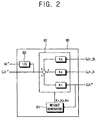
- an apparatus 3 for controlling the velocity of a motor 1 comprises an inverter 40, a current detector 50, a velocity estimator 60, a sensing velocity calculator 70, a reference velocity calculator 80, a velocity controller 10, a current controller 20, and a vector controller 30.
- the motor 1 controlled by the apparatus 3 comprises at least one of a surface-mounted permanent magnet synchronous motor (SPMSM) and an interior permanent magnet synchronous motor (IPMSM).
- SPMSM surface-mounted permanent magnet synchronous motor
- IPMSM interior permanent magnet synchronous motor
- the inverter 40 supplies the power to the motor 1.
- the inverter 40 controls the rotational velocity of the motor 1 by controlling the current supplied to the motor 1, such as a three-phase current, on the basis of a voltage command signal from the vector controller 30.
- the current detector 50 detects the current passing through each of a plurality of output terminals of the inverter 40.
- the current detector 50 also generates a detection current vector Is on the basis of the detected currents at the output terminals of the inverter 40.
- the generated detection current vector Is is fed to the velocity estimator 60.
- the current detector 50 may be provided in various configurations.
- the current detector 50 may directly detect all the three-phase currents of the motor 1 using a current transducer or a series shunt resistor.
- the current detector 50 may comprise two current transducers and two series shunt resistors, detect two phase currents of the motor 1 using the two current transducers and the two series shunt resistors, and estimate the remaining current on the basis of the detected two phase currents.
- the velocity estimator 60 receives the detection current vector Is output from the current detector 50, and estimates and outputs an estimation velocity ⁇ r_SL on the basis of the detection current vector Is.
- the estimation velocity ⁇ r_SL output from the velocity estimator 60 is input to the reference velocity calculator 80.
- the velocity estimator 60 generates the estimation velocity ⁇ r_SL of the motor 1 on the basis of the positional error of the rotor of the motor 1.
- the positional error of the rotor is calculated by estimating the back electromotive force of the motor 1.
- the back (or counter) electromotive force of the motor 1 may be calculated using a method for estimating the counter electromotive force as disclosed in "Sensorless control of interior permanent-magnet machine drives with zero-phase lag position estimation" by Hyun-bae Kim et al. (IEEE Transactions on Industry Applications, Volume: 39, Issue: 6, Nov.-Dec. 2003).
- the velocity estimator 60 may calculate the positional error of the rotor using a high frequency carrier signal.
- the position error may be calculated by a method for calculating the position error of the rotor using the high frequency carrier signal disclosed in "Position estimation in induction machine utilizing rotor bar slot harmonics and carrier-frequency signal injection" by M.W. Wegner et al. (IEEE Transactions on Industry Applications, Volume 36, Issue 3, May-June 2000).
- the sensing velocity calculator 70 senses the rotational position of the rotor and calculates the sensing velocity ⁇ r_S on the basis of the sensed rotational position of the rotor.
- the sensing velocity ⁇ r_S calculated using the sensing velocity calculator 70 is input to the reference velocity calculator 80.
- a sensor having a low resolution such as a Hall sensor for sensing the rotational position of the rotor used in the sensing velocity calculator 70. Having such a low resolution sensor reduces manufacturing costs.
- the reference velocity calculator 80 divides the overall velocity period of the motor 1 into a plurality of unit velocity periods on the basis of a command velocity ⁇ r* for controlling the rotational velocity of the motor 1.
- the command velocity ⁇ r* controls the rotational speed (or velocity) of the motor 1.
- the reference velocity calculator 80 multiplies at least one of the command velocity ⁇ r*, the sensing velocity ⁇ r_S and the estimated velocity ⁇ r_SL by a predetermined weight K1, K2 and K3, respectively. Then, the reference velocity calculator 80 calculates the sum of the sensing velocity ⁇ r_S, the estimation velocity ⁇ r_SL, and the command velocity ⁇ r* as a reference estimation velocity ⁇ r ⁇ of the motor 1.
- the reference velocity calculator 80 calculates a reference estimation position ⁇ r ⁇ of the motor 1 on the basis of the reference estimation velocity ⁇ r ⁇ .
- a method for calculating the reference estimation velocity ⁇ r ⁇ and/or the reference estimation position ⁇ r ⁇ calculated by the reference velocity calculator 80 is described later.
- a comparator 90 compares the reference estimation velocity ⁇ r ⁇ output from the reference velocity calculator 80 with the command velocity ⁇ r*, and outputs a comparison value indicative of the difference between the reference estimation velocity ⁇ r ⁇ and the command velocity ⁇ r*. Then, the velocity controller 10 generates a torque command Te* on the basis of the comparison value output from the comparator 90 and outputs the torque command Te* to the current controller 20.
- the current controller 20 receives the torque command Te* output from the velocity controller 10 and outputs a voltage vector command V*.
- the current controller 20 receives an estimation current value (not shown) calculated while the velocity estimator 60 estimates the estimation velocity ⁇ r_SL, and generates the voltage vector command V* taking account of the estimation current value.
- the vector controller 30 receives the voltage vector command V* output from the current controller 20 and the reference estimation position ⁇ r ⁇ output from the reference velocity calculator 80 and outputs voltage command signals Va,b,c* corresponding to each phase of the inverter 40 on the basis of the voltage vector command V* and the reference estimation position ⁇ r ⁇ .
- the reference velocity calculator 80 comprises a weight generator 81 outputting the weights K1, K2 and K3 multiplied to the command velocity ⁇ r*, the sensing velocity ⁇ r_S and the estimation velocity ⁇ r_SL and a reference velocity generator 82 calculating the reference estimation velocity ⁇ r ⁇ after multiplying the command velocity ⁇ r*, the sensing velocity ⁇ r_S, and the estimation velocity ⁇ r_SL by the weights K1, K2 and K3, respectively.
- the reference velocity calculator 80 further comprises an integrator 83 outputting the reference estimation position ⁇ r ⁇ .
- the reference velocity calculator 80 divides the overall velocity period of the motor 1 with the plurality of the unit velocity period.
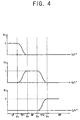
- the unit velocity period comprises a low-speed period LP, a middle-speed period MP, a high-speed period HP, a first conversion period TP1 between the low-speed period LP and the middle-speed period MP and a second conversion period TP2 between the middle-speed period MP and the high-speed period HP.
- the weight generator 81 receives the command velocity ⁇ r* and determines the present unit velocity period on the basis of the command velocity ⁇ r*. For example, as shown in Figures 3 and 4, when the command velocity ⁇ r* ranges between a zero velocity and a first velocity V1, the weight generator 81 determines the present unit velocity period as the low-speed period LP.
- the weight generator 81 determines the present unit period of velocity as the first conversion period TP1 when the command velocity ⁇ r* ranges between the first velocity V1 and a second velocity V2, as the middle-speed period MP when the command velocity ⁇ r* ranges between the second velocity V2 and a third velocity V3, as the second conversion period TP2 when the command velocity ⁇ r* ranges between the third velocity V3 and a fourth velocity V4, and as the high-speed period HP when the command velocity ⁇ r* is greater than the fourth velocity V4.
- the weight generator 81 sets a weight corresponding to the command velocity ⁇ r* (hereinafter, referred to as "a command weight K1”) as “1”, sets a weight corresponding to the sensing velocity ⁇ r_S (hereinafter, referred to as “a sensing weight K2”) as “0” and sets a weight corresponding to the estimation velocity ⁇ r_SL (hereinafter, referred to as "a estimation weight K3”) as "0".
- the command velocity ⁇ r* is output from the reference velocity calculator 80 as the reference estimation velocity ⁇ r ⁇ in the low-speed period LP.
- the reference the command velocity ⁇ r* is output as the estimation velocity ⁇ r ⁇ . This is because the calculation of the rotation velocity using the Hall sensor and sensorless control are difficult.
- the weight generator 81 sets the sensing weight K2 sets as "1", sets the command weight K1 as "0” and sets the estimation weight K3 as "0".
- the sensing velocity ⁇ r_S is output from the reference velocity calculator 80 as the reference estimation velocity ⁇ r ⁇ in the middle-speed period MP.
- the weight generator 81 sets the estimation weight K3 as “1”, sets the command weight K1 as “0” and sets the sensing weight K2 as "0".
- the estimation velocity ⁇ r_SL is output from the reference velocity calculator 80 as the reference estimation velocity ⁇ r ⁇ at the high-speed period HP.
- the weight generator 81 multiplies the command velocity ⁇ r* and the sensing velocity ⁇ r_S by the command weight K1 and the sensing weight K2 varied according to the command velocity ⁇ r*, respectively. Further, the weight generator 81 outputs the sum of the weighted command velocity ⁇ r* and the weighted sensing velocity ⁇ r_S as the reference estimation velocity ⁇ r ⁇ .
- the weight generator 81 decreases the command weight K1 output as "1" at the low-speed period LP and increases the sensing weight K2 output as "0" at the low-speed period LP in accordance with an increase of the command velocity ⁇ r*.
- the reference velocity generator 82 multiplies the command weight K1 decreased in accordance with the increase of the command velocity ⁇ r* by the command velocity ⁇ r*, multiplies the sensing weight K2 increased in accordance with the increase of the command velocity ⁇ r* by the sensing velocity ⁇ r_S, and outputs the sum of the command velocity ⁇ r* and the sensing velocity ⁇ r_S as the reference estimation velocity ⁇ r ⁇ .
- the weight generator 81 decreases the sensing weight K2 output as "1" in the middle-speed period MP and increases the estimation weight K3 output as "0" in the middle-speed period MP in accordance with an increase of the command velocity ⁇ r*.
- the reference velocity generator 82 multiplies the sensing velocity ⁇ r_S by the sensing weight K2 decreased in accordance with the increase command velocity ⁇ r*, multiplies the estimation velocity ⁇ r_SL by the estimation weight K3 increased in accordance with the increase of the command velocity ⁇ r*, and outputs the sum of the sensing velocity ⁇ r_S and the estimation velocity ⁇ r_SL as the reference estimation velocity ⁇ r ⁇ .
- the weight generator 81 increases and/or decreases each weight K1, K2 and K3 linearly during the first conversion period TP1 and the second conversion period TP2 in accordance with the increase of the command velocity ⁇ r* for example. Further, in Figure 4, the weight generator 81 increases and/or decreases each weight K1, K2 and K3 sigmoidally in the first conversion period TP1 and the second conversion period TP2 in accordance with the increase of the command velocity ⁇ r* as a further example.
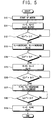
- the weight generator 81 when the motor 1 initially starts at operation S10, the weight generator 81 outputs the command weight K1 as “1”, the sensing weight K2 as “0”, and the estimation weight K3 as "0” at operation S11. At this time, each weight K1, K2 and K3 output from the weight generator 81 is input to the reference velocity generator 82.
- the reference velocity generator 82 multiplies the command velocity ⁇ r*, the sensing velocity ⁇ r_S, and the estimation velocity ⁇ r_SL by weights K1, K2 and K3, respectively.
- the reference velocity generator 82 outputs the sum of the command velocity ⁇ r* multiplied by the command weight K1, the sensing velocity ⁇ r_S multiplied by the sensing weight K2, and the estimation velocity ⁇ r_SL multiplied by the estimation weight K3 as the reference estimation velocity ⁇ r ⁇ .
- the weight generator 81 determines whether the command velocity ⁇ r* exceeds the first velocity V1 at operation S12.
- the weight generator 81 decreases the command weight K1 from "1", increases the sensing weight K2 from “0” in accordance with the increase in the command velocity ⁇ r*, and sets estimation weight K3 to output as "0" at operation S13.
- the weight generator 81 determines whether the command velocity ⁇ r* exceeds the second velocity V2 at operation S14. Then, the weight generator 81 sets the sensing weight K2 as "1", sets the command weight K1 as "0” and sets the estimation weight K3 as "0", when the command velocity ⁇ r* exceeds the second velocity V2, that is, the command velocity ⁇ r* enters the middle-speed period MP, at operation S15.
- the weight generator 81 determines whether the command velocity ⁇ r* exceeds the third velocity V3 at operation S16.
- the weight generator 81 decreases the sensing weight K2 from "1”, increases the estimation weight K3 from "0” in accordance with the increase of the command velocity ⁇ r*, and sets the command weight K1 as "0", when the command velocity ⁇ r* exceeds the third velocity V3, that is, enters the second conversion period TP2 at operation S17.
- the weight generator 81 determines whether the command velocity ⁇ r* exceeds the fourth velocity V4 at operation S18. The weight generator 81 then sets the estimation weight K3 as "1", sets the command weight K1 as "0” and sets the sensing weight K2 as "0" when the command velocity ⁇ r* exceeds the fourth velocity V4, that is, the command velocity ⁇ r* enters the high-speed period HP at operation S19.
- the reference estimation velocity ⁇ r ⁇ which is robust against a fluctuation of a disturbance torque at the start of the motor 1, and is accurate over the total velocity period of the motor 1, is calculated, before the rotation velocity of the motor 1 exceeds the fourth velocity V4 in which the sensorless control is feasible.
Landscapes
- Engineering & Computer Science (AREA)
- Power Engineering (AREA)
- Control Of Ac Motors In General (AREA)
- Control Of Electric Motors In General (AREA)
- Control Of Motors That Do Not Use Commutators (AREA)
Applications Claiming Priority (1)
| Application Number | Priority Date | Filing Date | Title |
|---|---|---|---|
| KR1020040103251A KR100665061B1 (ko) | 2004-12-08 | 2004-12-08 | 모터의 속도 제어장치 및 속도 제어방법 |
Publications (3)
| Publication Number | Publication Date |
|---|---|
| EP1684411A2 true EP1684411A2 (fr) | 2006-07-26 |
| EP1684411A3 EP1684411A3 (fr) | 2006-11-22 |
| EP1684411B1 EP1684411B1 (fr) | 2009-04-08 |
Family
ID=36499553
Family Applications (1)
| Application Number | Title | Priority Date | Filing Date |
|---|---|---|---|
| EP05111269A Expired - Lifetime EP1684411B1 (fr) | 2004-12-08 | 2005-11-24 | Commande d'un moteur |
Country Status (5)
| Country | Link |
|---|---|
| US (1) | US7405534B2 (fr) |
| EP (1) | EP1684411B1 (fr) |
| KR (1) | KR100665061B1 (fr) |
| CN (1) | CN100373767C (fr) |
| DE (1) | DE602005013742D1 (fr) |
Families Citing this family (9)
| Publication number | Priority date | Publication date | Assignee | Title |
|---|---|---|---|---|
| JP4847060B2 (ja) * | 2005-07-15 | 2011-12-28 | 日立オートモティブシステムズ株式会社 | 交流モータ駆動装置及びその制御方法 |
| KR101330660B1 (ko) * | 2006-09-08 | 2013-11-15 | 삼성전자주식회사 | 스캐닝 유닛의 제어가 가능한 화상형성장치, 그의 스캐닝 유닛 제어 방법 및 모터 제어 장치 |
| JP4284355B2 (ja) * | 2006-12-28 | 2009-06-24 | 株式会社日立産機システム | 永久磁石モータの高応答制御装置 |
| US20120146402A1 (en) * | 2010-12-09 | 2012-06-14 | Siemens Industry, Inc. | Control system for regulating bus voltage for an electric shovel |
| KR101228665B1 (ko) * | 2011-12-21 | 2013-01-31 | 삼성전기주식회사 | 모터 구동 장치 및 방법 |
| KR20140116728A (ko) * | 2013-03-25 | 2014-10-06 | 엘지전자 주식회사 | 센서리스 bldc 모터의 기동 장치 및 방법 |
| US20150188461A1 (en) * | 2013-12-30 | 2015-07-02 | Samsung Electro-Mechanics Co., Ltd. | Motor driving control apparatus and method, and motor driving system using the same |
| CN111614301B (zh) * | 2019-02-26 | 2022-01-04 | 达明机器人股份有限公司 | 马达编码器的动态采样方法 |
| WO2021120100A1 (fr) * | 2019-12-19 | 2021-06-24 | 瑞声声学科技(深圳)有限公司 | Procédé de commande de signal de moteur électrique, dispositif terminal et support de stockage |
Citations (1)
| Publication number | Priority date | Publication date | Assignee | Title |
|---|---|---|---|---|
| US6081093A (en) | 1996-12-05 | 2000-06-27 | Kabushiki Kaisha Yaskawa Denki | Sensorless control method and apparatus of permanent magnet synchronous motor |
Family Cites Families (22)
| Publication number | Priority date | Publication date | Assignee | Title |
|---|---|---|---|---|
| US5585709A (en) * | 1993-12-22 | 1996-12-17 | Wisconsin Alumni Research Foundation | Method and apparatus for transducerless position and velocity estimation in drives for AC machines |
| JP3226253B2 (ja) * | 1995-09-11 | 2001-11-05 | 株式会社東芝 | 永久磁石同期電動機の制御装置 |
| JP3213796B2 (ja) | 1995-12-15 | 2001-10-02 | 松下電器産業株式会社 | サーボモータ制御装置 |
| DE59709336D1 (de) | 1996-09-21 | 2003-03-27 | Diehl Ako Stiftung Gmbh & Co | Einrichtung zur Antriebsstromsteuerung eines elektrisch kommutierten Permanentmagnet-Motors |
| JP3245098B2 (ja) | 1997-09-03 | 2002-01-07 | 株式会社長田中央研究所 | センサレス・ブラシレス直流モータの駆動方法 |
| JPH11187699A (ja) | 1997-12-24 | 1999-07-09 | Hitachi Ltd | 誘導電動機の速度制御方法 |
| US6137258A (en) * | 1998-10-26 | 2000-10-24 | General Electric Company | System for speed-sensorless control of an induction machine |
| JP2001204190A (ja) | 2000-01-17 | 2001-07-27 | Yaskawa Electric Corp | 初期磁極位置推定装置その誤差調整方法 |
| JP4403626B2 (ja) | 2000-03-22 | 2010-01-27 | ダイキン工業株式会社 | Srモータセンサレス制御方法およびその装置 |
| US6552509B2 (en) * | 2000-05-10 | 2003-04-22 | Gti Electroproject B.V. | Method and a device for sensorless estimating the relative angular position between the stator and rotor of a three-phase synchronous motor |
| JP3832257B2 (ja) * | 2001-02-26 | 2006-10-11 | 株式会社日立製作所 | 同期モータの起動制御方法と制御装置 |
| KR100428505B1 (ko) * | 2001-07-06 | 2004-04-28 | 삼성전자주식회사 | 유도전동기의 속도 및 회전자 자속 추정방법 |
| KR100408061B1 (ko) | 2001-07-09 | 2003-12-03 | 엘지전자 주식회사 | 센서리스 비엘디씨 모터의 회전자 위치검출방법 |
| KR100431287B1 (ko) | 2001-07-26 | 2004-05-12 | 동양기전 주식회사 | 무센서 브러시리스 모터의 기동방법 |
| JP3969093B2 (ja) * | 2002-01-07 | 2007-08-29 | 松下電器産業株式会社 | サーボモータの制御装置 |
| KR100451227B1 (ko) | 2002-02-05 | 2004-10-02 | 엘지전자 주식회사 | 동기릴럭턴스 모터의 센서리스 속도제어방법 |
| JP4370754B2 (ja) * | 2002-04-02 | 2009-11-25 | 株式会社安川電機 | 交流電動機のセンサレス制御装置および制御方法 |
| JP3695436B2 (ja) * | 2002-09-18 | 2005-09-14 | 株式会社日立製作所 | 位置センサレスモータ制御方法および装置 |
| KR100484819B1 (ko) * | 2002-10-10 | 2005-04-22 | 엘지전자 주식회사 | 동기 릴럭턴스 모터의 제어시스템 |
| KR100511274B1 (ko) | 2002-11-08 | 2005-08-31 | 엘지전자 주식회사 | 영구자석형 동기모터의 센서리스 제어방법 |
| US20040100220A1 (en) | 2002-11-25 | 2004-05-27 | Zhenxing Fu | Weighted higher-order proportional-integral current regulator for synchronous machines |
| KR20040097021A (ko) * | 2004-10-12 | 2004-11-17 | 순천대학교 산학협력단 | 유도전동기의 고성능 제어를 위한 적응 fnn 제어 시스템 |
-
2004
- 2004-12-08 KR KR1020040103251A patent/KR100665061B1/ko not_active Expired - Fee Related
-
2005
- 2005-11-01 US US11/262,846 patent/US7405534B2/en not_active Expired - Fee Related
- 2005-11-24 DE DE602005013742T patent/DE602005013742D1/de not_active Expired - Lifetime
- 2005-11-24 EP EP05111269A patent/EP1684411B1/fr not_active Expired - Lifetime
- 2005-12-05 CN CNB200510129503XA patent/CN100373767C/zh not_active Expired - Fee Related
Patent Citations (1)
| Publication number | Priority date | Publication date | Assignee | Title |
|---|---|---|---|---|
| US6081093A (en) | 1996-12-05 | 2000-06-27 | Kabushiki Kaisha Yaskawa Denki | Sensorless control method and apparatus of permanent magnet synchronous motor |
Non-Patent Citations (2)
| Title |
|---|
| HYUN-BAE KIM: "Sensorless control of interior permanent-magnet machine drives with zero-phase lag position estimation", IEEE TRANSACTIONS ON INDUSTRY APPLICATIONS, vol. 39, November 2003 (2003-11-01) |
| M.W. WEGNER: "Position estimation in induction machine utilizing rotor bar slot harmonics and carrier-frequency signal injection", IEEE TRANSACTIONS ON INDUSTRY APPLICATIONS, vol. 36, May 2000 (2000-05-01) |
Also Published As
| Publication number | Publication date |
|---|---|
| EP1684411A3 (fr) | 2006-11-22 |
| CN100373767C (zh) | 2008-03-05 |
| US20060119309A1 (en) | 2006-06-08 |
| CN1787358A (zh) | 2006-06-14 |
| EP1684411B1 (fr) | 2009-04-08 |
| DE602005013742D1 (de) | 2009-05-20 |
| KR100665061B1 (ko) | 2007-01-09 |
| US7405534B2 (en) | 2008-07-29 |
| KR20060064407A (ko) | 2006-06-13 |
Similar Documents
| Publication | Publication Date | Title |
|---|---|---|
| Hurst et al. | Sensorless speed measurement using current harmonic spectral estimation in induction machine drives | |
| JP3645509B2 (ja) | 誘導電動機のセンサレスベクトル制御システムおよびセンサレスベクトル制御方法 | |
| EP1850471B1 (fr) | Système et procédé d'estimation de la vitesse d'un moteur à excitation transitoire | |
| JP5052723B2 (ja) | 低リップル永久磁石モータ制御 | |
| US9825579B2 (en) | Temperature estimating apparatus for synchronous motor | |
| JP4221307B2 (ja) | 同期電動機の制御装置,電気機器およびモジュール | |
| US10241130B2 (en) | Circuit and method to detect failure of speed estimation/speed measurement of a multi-phase AC motor | |
| JP6667076B2 (ja) | モータ制御装置、およびこのモータ制御装置におけるトルク定数の補正方法 | |
| EP2706659A1 (fr) | Système pour corriger une position estimée d'un rotor d'une machine électrique | |
| Hurst et al. | Speed sensorless field-oriented control of induction machines using current harmonic spectral estimation | |
| JP2002034278A (ja) | 電動機の磁極位置検出装置 | |
| Schroedl | Sensorless control of permanent magnet synchronous motors | |
| US20020021105A1 (en) | Sensorless vector control apparatus and method thereof | |
| EP1684411B1 (fr) | Commande d'un moteur | |
| EP2493067B1 (fr) | Procédé et appareil pour estimer l'angle de rotor d'un moteur à réluctance synchrone | |
| WO2016161213A1 (fr) | Réglage de retard fractionnaire dans une architecture de commande orientée champ | |
| KR20190036667A (ko) | 전동기 속도 추정 장치 및 방법 | |
| JP4127000B2 (ja) | モータ制御装置 | |
| EP1755211A1 (fr) | Estimation de resistance d'un moteur électric à courant alternatif | |
| US20040060348A1 (en) | Method for detecting the magnetic flux the rotor position and/or the rotational speed | |
| US20040037541A1 (en) | BLDC motor speed control apparatus and method | |
| Hurst et al. | Sensorless speed measurement using current harmonic spectral estimation in induction machine drives | |
| KR20140048581A (ko) | 역기전력 신호를 이용한 센서리스 모터의 오류 판단장치 | |
| KR100561733B1 (ko) | 순시무효전력을 이용한 영구자석 동기전동기의 센서리스제어방법 | |
| KR100668973B1 (ko) | 모터의 속도/위치 추정방법 |
Legal Events
| Date | Code | Title | Description |
|---|---|---|---|
| PUAI | Public reference made under article 153(3) epc to a published international application that has entered the european phase |
Free format text: ORIGINAL CODE: 0009012 |
|
| AK | Designated contracting states |
Kind code of ref document: A2 Designated state(s): AT BE BG CH CY CZ DE DK EE ES FI FR GB GR HU IE IS IT LI LT LU LV MC NL PL PT RO SE SI SK TR |
|
| AX | Request for extension of the european patent |
Extension state: AL BA HR MK YU |
|
| PUAL | Search report despatched |
Free format text: ORIGINAL CODE: 0009013 |
|
| AK | Designated contracting states |
Kind code of ref document: A3 Designated state(s): AT BE BG CH CY CZ DE DK EE ES FI FR GB GR HU IE IS IT LI LT LU LV MC NL PL PT RO SE SI SK TR |
|
| AX | Request for extension of the european patent |
Extension state: AL BA HR MK YU |
|
| RIC1 | Information provided on ipc code assigned before grant |
Ipc: G01P 3/489 20060101ALI20061018BHEP Ipc: H02P 23/14 20060101ALI20061018BHEP Ipc: H02P 21/14 20060101AFI20060616BHEP |
|
| 17P | Request for examination filed |
Effective date: 20070505 |
|
| 17Q | First examination report despatched |
Effective date: 20070608 |
|
| AKX | Designation fees paid |
Designated state(s): DE FR GB |
|
| GRAP | Despatch of communication of intention to grant a patent |
Free format text: ORIGINAL CODE: EPIDOSNIGR1 |
|
| RTI1 | Title (correction) |
Free format text: MOTOR CONTROL |
|
| RAP1 | Party data changed (applicant data changed or rights of an application transferred) |
Owner name: SAMSUNG ELECTRONICS CO., LTD. |
|
| GRAS | Grant fee paid |
Free format text: ORIGINAL CODE: EPIDOSNIGR3 |
|
| GRAA | (expected) grant |
Free format text: ORIGINAL CODE: 0009210 |
|
| AK | Designated contracting states |
Kind code of ref document: B1 Designated state(s): DE FR GB |
|
| REG | Reference to a national code |
Ref country code: GB Ref legal event code: FG4D |
|
| REF | Corresponds to: |
Ref document number: 602005013742 Country of ref document: DE Date of ref document: 20090520 Kind code of ref document: P |
|
| PLBE | No opposition filed within time limit |
Free format text: ORIGINAL CODE: 0009261 |
|
| STAA | Information on the status of an ep patent application or granted ep patent |
Free format text: STATUS: NO OPPOSITION FILED WITHIN TIME LIMIT |
|
| 26N | No opposition filed |
Effective date: 20100111 |
|
| REG | Reference to a national code |
Ref country code: FR Ref legal event code: PLFP Year of fee payment: 12 |
|
| REG | Reference to a national code |
Ref country code: FR Ref legal event code: PLFP Year of fee payment: 13 |
|
| PGFP | Annual fee paid to national office [announced via postgrant information from national office to epo] |
Ref country code: DE Payment date: 20171018 Year of fee payment: 13 Ref country code: FR Payment date: 20171020 Year of fee payment: 13 |
|
| PGFP | Annual fee paid to national office [announced via postgrant information from national office to epo] |
Ref country code: GB Payment date: 20171019 Year of fee payment: 13 |
|
| REG | Reference to a national code |
Ref country code: DE Ref legal event code: R119 Ref document number: 602005013742 Country of ref document: DE |
|
| GBPC | Gb: european patent ceased through non-payment of renewal fee |
Effective date: 20181124 |
|
| PG25 | Lapsed in a contracting state [announced via postgrant information from national office to epo] |
Ref country code: FR Free format text: LAPSE BECAUSE OF NON-PAYMENT OF DUE FEES Effective date: 20181130 Ref country code: DE Free format text: LAPSE BECAUSE OF NON-PAYMENT OF DUE FEES Effective date: 20190601 |
|
| PG25 | Lapsed in a contracting state [announced via postgrant information from national office to epo] |
Ref country code: GB Free format text: LAPSE BECAUSE OF NON-PAYMENT OF DUE FEES Effective date: 20181124 |