EP1685385B1 - Formate für die optische analyse sowie verfahren zur herstellung davon - Google Patents
Formate für die optische analyse sowie verfahren zur herstellung davon Download PDFInfo
- Publication number
- EP1685385B1 EP1685385B1 EP04796799A EP04796799A EP1685385B1 EP 1685385 B1 EP1685385 B1 EP 1685385B1 EP 04796799 A EP04796799 A EP 04796799A EP 04796799 A EP04796799 A EP 04796799A EP 1685385 B1 EP1685385 B1 EP 1685385B1
- Authority
- EP
- European Patent Office
- Prior art keywords
- format
- component
- format component
- read
- optical
- Prior art date
- Legal status (The legal status is an assumption and is not a legal conclusion. Google has not performed a legal analysis and makes no representation as to the accuracy of the status listed.)
- Expired - Lifetime
Links
- 230000003287 optical effect Effects 0.000 title claims abstract description 151
- 238000000034 method Methods 0.000 title claims description 25
- 238000004458 analytical method Methods 0.000 title claims description 15
- 238000004519 manufacturing process Methods 0.000 title abstract description 9
- 239000003153 chemical reaction reagent Substances 0.000 claims description 12
- 238000000465 moulding Methods 0.000 claims description 12
- 239000000853 adhesive Substances 0.000 claims description 8
- 230000001070 adhesive effect Effects 0.000 claims description 8
- 239000000463 material Substances 0.000 claims description 7
- 238000003466 welding Methods 0.000 claims description 2
- 238000012360 testing method Methods 0.000 abstract description 15
- 239000012530 fluid Substances 0.000 abstract description 13
- 238000010276 construction Methods 0.000 abstract description 6
- 230000015572 biosynthetic process Effects 0.000 description 4
- 239000000126 substance Substances 0.000 description 4
- 230000005540 biological transmission Effects 0.000 description 3
- 238000005259 measurement Methods 0.000 description 3
- WQZGKKKJIJFFOK-GASJEMHNSA-N Glucose Natural products OC[C@H]1OC(O)[C@H](O)[C@@H](O)[C@@H]1O WQZGKKKJIJFFOK-GASJEMHNSA-N 0.000 description 2
- 239000008280 blood Substances 0.000 description 2
- 210000004369 blood Anatomy 0.000 description 2
- 210000001124 body fluid Anatomy 0.000 description 2
- 230000008021 deposition Effects 0.000 description 2
- 239000008103 glucose Substances 0.000 description 2
- 238000012986 modification Methods 0.000 description 2
- 230000004048 modification Effects 0.000 description 2
- 238000004806 packaging method and process Methods 0.000 description 2
- 239000005041 Mylar™ Substances 0.000 description 1
- NIXOWILDQLNWCW-UHFFFAOYSA-N acrylic acid group Chemical group C(C=C)(=O)O NIXOWILDQLNWCW-UHFFFAOYSA-N 0.000 description 1
- 230000002411 adverse Effects 0.000 description 1
- 238000013459 approach Methods 0.000 description 1
- 230000009286 beneficial effect Effects 0.000 description 1
- 206010012601 diabetes mellitus Diseases 0.000 description 1
- 238000009792 diffusion process Methods 0.000 description 1
- 210000003722 extracellular fluid Anatomy 0.000 description 1
- 238000001746 injection moulding Methods 0.000 description 1
- 230000003993 interaction Effects 0.000 description 1
- 238000005304 joining Methods 0.000 description 1
- 230000013011 mating Effects 0.000 description 1
- 238000010339 medical test Methods 0.000 description 1
- 238000012544 monitoring process Methods 0.000 description 1
- 239000004033 plastic Substances 0.000 description 1
- 229920000515 polycarbonate Polymers 0.000 description 1
- 239000004417 polycarbonate Substances 0.000 description 1
- 229920000728 polyester Polymers 0.000 description 1
- 238000004080 punching Methods 0.000 description 1
- 238000002798 spectrophotometry method Methods 0.000 description 1
Images


Classifications
-
- G—PHYSICS
- G11—INFORMATION STORAGE
- G11B—INFORMATION STORAGE BASED ON RELATIVE MOVEMENT BETWEEN RECORD CARRIER AND TRANSDUCER
- G11B11/00—Recording on or reproducing from the same record carrier wherein for these two operations the methods are covered by different main groups of groups G11B3/00 - G11B7/00 or by different subgroups of group G11B9/00; Record carriers therefor
- G11B11/10—Recording on or reproducing from the same record carrier wherein for these two operations the methods are covered by different main groups of groups G11B3/00 - G11B7/00 or by different subgroups of group G11B9/00; Record carriers therefor using recording by magnetic means or other means for magnetisation or demagnetisation of a record carrier, e.g. light induced spin magnetisation; Demagnetisation by thermal or stress means in the presence or not of an orienting magnetic field
- G11B11/105—Recording on or reproducing from the same record carrier wherein for these two operations the methods are covered by different main groups of groups G11B3/00 - G11B7/00 or by different subgroups of group G11B9/00; Record carriers therefor using recording by magnetic means or other means for magnetisation or demagnetisation of a record carrier, e.g. light induced spin magnetisation; Demagnetisation by thermal or stress means in the presence or not of an orienting magnetic field using a beam of light or a magnetic field for recording by change of magnetisation and a beam of light for reproducing, i.e. magneto-optical, e.g. light-induced thermomagnetic recording, spin magnetisation recording, Kerr or Faraday effect reproducing
-
- G—PHYSICS
- G01—MEASURING; TESTING
- G01N—INVESTIGATING OR ANALYSING MATERIALS BY DETERMINING THEIR CHEMICAL OR PHYSICAL PROPERTIES
- G01N21/00—Investigating or analysing materials by the use of optical means, i.e. using sub-millimetre waves, infrared, visible or ultraviolet light
- G01N21/17—Systems in which incident light is modified in accordance with the properties of the material investigated
- G01N21/47—Scattering, i.e. diffuse reflection
- G01N21/49—Scattering, i.e. diffuse reflection within a body or fluid
- G01N21/51—Scattering, i.e. diffuse reflection within a body or fluid inside a container, e.g. in an ampoule
-
- B—PERFORMING OPERATIONS; TRANSPORTING
- B01—PHYSICAL OR CHEMICAL PROCESSES OR APPARATUS IN GENERAL
- B01L—CHEMICAL OR PHYSICAL LABORATORY APPARATUS FOR GENERAL USE
- B01L3/00—Containers or dishes for laboratory use, e.g. laboratory glassware; Droppers
- B01L3/50—Containers for the purpose of retaining a material to be analysed, e.g. test tubes
- B01L3/502—Containers for the purpose of retaining a material to be analysed, e.g. test tubes with fluid transport, e.g. in multi-compartment structures
- B01L3/5027—Containers for the purpose of retaining a material to be analysed, e.g. test tubes with fluid transport, e.g. in multi-compartment structures by integrated microfluidic structures, i.e. dimensions of channels and chambers are such that surface tension forces are important, e.g. lab-on-a-chip
- B01L3/502707—Containers for the purpose of retaining a material to be analysed, e.g. test tubes with fluid transport, e.g. in multi-compartment structures by integrated microfluidic structures, i.e. dimensions of channels and chambers are such that surface tension forces are important, e.g. lab-on-a-chip characterised by the manufacture of the container or its components
-
- B—PERFORMING OPERATIONS; TRANSPORTING
- B01—PHYSICAL OR CHEMICAL PROCESSES OR APPARATUS IN GENERAL
- B01L—CHEMICAL OR PHYSICAL LABORATORY APPARATUS FOR GENERAL USE
- B01L3/00—Containers or dishes for laboratory use, e.g. laboratory glassware; Droppers
- B01L3/50—Containers for the purpose of retaining a material to be analysed, e.g. test tubes
- B01L3/502—Containers for the purpose of retaining a material to be analysed, e.g. test tubes with fluid transport, e.g. in multi-compartment structures
- B01L3/5027—Containers for the purpose of retaining a material to be analysed, e.g. test tubes with fluid transport, e.g. in multi-compartment structures by integrated microfluidic structures, i.e. dimensions of channels and chambers are such that surface tension forces are important, e.g. lab-on-a-chip
- B01L3/502715—Containers for the purpose of retaining a material to be analysed, e.g. test tubes with fluid transport, e.g. in multi-compartment structures by integrated microfluidic structures, i.e. dimensions of channels and chambers are such that surface tension forces are important, e.g. lab-on-a-chip characterised by interfacing components, e.g. fluidic, electrical, optical or mechanical interfaces
-
- G—PHYSICS
- G01—MEASURING; TESTING
- G01N—INVESTIGATING OR ANALYSING MATERIALS BY DETERMINING THEIR CHEMICAL OR PHYSICAL PROPERTIES
- G01N21/00—Investigating or analysing materials by the use of optical means, i.e. using sub-millimetre waves, infrared, visible or ultraviolet light
- G01N21/01—Arrangements or apparatus for facilitating the optical investigation
- G01N21/03—Cuvette constructions
-
- A—HUMAN NECESSITIES
- A61—MEDICAL OR VETERINARY SCIENCE; HYGIENE
- A61B—DIAGNOSIS; SURGERY; IDENTIFICATION
- A61B2562/00—Details of sensors; Constructional details of sensor housings or probes; Accessories for sensors
- A61B2562/02—Details of sensors specially adapted for in-vivo measurements
- A61B2562/0295—Strip shaped analyte sensors for apparatus classified in A61B5/145 or A61B5/157
-
- B—PERFORMING OPERATIONS; TRANSPORTING
- B01—PHYSICAL OR CHEMICAL PROCESSES OR APPARATUS IN GENERAL
- B01L—CHEMICAL OR PHYSICAL LABORATORY APPARATUS FOR GENERAL USE
- B01L2200/00—Solutions for specific problems relating to chemical or physical laboratory apparatus
- B01L2200/02—Adapting objects or devices to another
- B01L2200/025—Align devices or objects to ensure defined positions relative to each other
-
- B—PERFORMING OPERATIONS; TRANSPORTING
- B01—PHYSICAL OR CHEMICAL PROCESSES OR APPARATUS IN GENERAL
- B01L—CHEMICAL OR PHYSICAL LABORATORY APPARATUS FOR GENERAL USE
- B01L2200/00—Solutions for specific problems relating to chemical or physical laboratory apparatus
- B01L2200/02—Adapting objects or devices to another
- B01L2200/026—Fluid interfacing between devices or objects, e.g. connectors, inlet details
- B01L2200/027—Fluid interfacing between devices or objects, e.g. connectors, inlet details for microfluidic devices
-
- B—PERFORMING OPERATIONS; TRANSPORTING
- B01—PHYSICAL OR CHEMICAL PROCESSES OR APPARATUS IN GENERAL
- B01L—CHEMICAL OR PHYSICAL LABORATORY APPARATUS FOR GENERAL USE
- B01L2200/00—Solutions for specific problems relating to chemical or physical laboratory apparatus
- B01L2200/12—Specific details about manufacturing devices
-
- B—PERFORMING OPERATIONS; TRANSPORTING
- B01—PHYSICAL OR CHEMICAL PROCESSES OR APPARATUS IN GENERAL
- B01L—CHEMICAL OR PHYSICAL LABORATORY APPARATUS FOR GENERAL USE
- B01L2300/00—Additional constructional details
- B01L2300/08—Geometry, shape and general structure
- B01L2300/0809—Geometry, shape and general structure rectangular shaped
- B01L2300/0825—Test strips
-
- B—PERFORMING OPERATIONS; TRANSPORTING
- B01—PHYSICAL OR CHEMICAL PROCESSES OR APPARATUS IN GENERAL
- B01L—CHEMICAL OR PHYSICAL LABORATORY APPARATUS FOR GENERAL USE
- B01L2300/00—Additional constructional details
- B01L2300/08—Geometry, shape and general structure
- B01L2300/0887—Laminated structure
-
- B—PERFORMING OPERATIONS; TRANSPORTING
- B01—PHYSICAL OR CHEMICAL PROCESSES OR APPARATUS IN GENERAL
- B01L—CHEMICAL OR PHYSICAL LABORATORY APPARATUS FOR GENERAL USE
- B01L2400/00—Moving or stopping fluids
- B01L2400/04—Moving fluids with specific forces or mechanical means
- B01L2400/0403—Moving fluids with specific forces or mechanical means specific forces
- B01L2400/0406—Moving fluids with specific forces or mechanical means specific forces capillary forces
-
- G—PHYSICS
- G01—MEASURING; TESTING
- G01N—INVESTIGATING OR ANALYSING MATERIALS BY DETERMINING THEIR CHEMICAL OR PHYSICAL PROPERTIES
- G01N21/00—Investigating or analysing materials by the use of optical means, i.e. using sub-millimetre waves, infrared, visible or ultraviolet light
- G01N21/01—Arrangements or apparatus for facilitating the optical investigation
- G01N21/03—Cuvette constructions
- G01N2021/0321—One time use cells, e.g. integrally moulded
-
- G—PHYSICS
- G01—MEASURING; TESTING
- G01N—INVESTIGATING OR ANALYSING MATERIALS BY DETERMINING THEIR CHEMICAL OR PHYSICAL PROPERTIES
- G01N21/00—Investigating or analysing materials by the use of optical means, i.e. using sub-millimetre waves, infrared, visible or ultraviolet light
- G01N21/01—Arrangements or apparatus for facilitating the optical investigation
- G01N21/03—Cuvette constructions
- G01N2021/0346—Capillary cells; Microcells
-
- G—PHYSICS
- G01—MEASURING; TESTING
- G01N—INVESTIGATING OR ANALYSING MATERIALS BY DETERMINING THEIR CHEMICAL OR PHYSICAL PROPERTIES
- G01N21/00—Investigating or analysing materials by the use of optical means, i.e. using sub-millimetre waves, infrared, visible or ultraviolet light
- G01N21/01—Arrangements or apparatus for facilitating the optical investigation
- G01N21/03—Cuvette constructions
- G01N2021/0378—Shapes
-
- Y—GENERAL TAGGING OF NEW TECHNOLOGICAL DEVELOPMENTS; GENERAL TAGGING OF CROSS-SECTIONAL TECHNOLOGIES SPANNING OVER SEVERAL SECTIONS OF THE IPC; TECHNICAL SUBJECTS COVERED BY FORMER USPC CROSS-REFERENCE ART COLLECTIONS [XRACs] AND DIGESTS
- Y10—TECHNICAL SUBJECTS COVERED BY FORMER USPC
- Y10T—TECHNICAL SUBJECTS COVERED BY FORMER US CLASSIFICATION
- Y10T29/00—Metal working
- Y10T29/49—Method of mechanical manufacture
- Y10T29/49826—Assembling or joining
- Y10T29/49895—Associating parts by use of aligning means [e.g., use of a drift pin or a "fixture"]
-
- Y—GENERAL TAGGING OF NEW TECHNOLOGICAL DEVELOPMENTS; GENERAL TAGGING OF CROSS-SECTIONAL TECHNOLOGIES SPANNING OVER SEVERAL SECTIONS OF THE IPC; TECHNICAL SUBJECTS COVERED BY FORMER USPC CROSS-REFERENCE ART COLLECTIONS [XRACs] AND DIGESTS
- Y10—TECHNICAL SUBJECTS COVERED BY FORMER USPC
- Y10T—TECHNICAL SUBJECTS COVERED BY FORMER US CLASSIFICATION
- Y10T29/00—Metal working
- Y10T29/49—Method of mechanical manufacture
- Y10T29/49826—Assembling or joining
- Y10T29/49895—Associating parts by use of aligning means [e.g., use of a drift pin or a "fixture"]
- Y10T29/49899—Associating parts by use of aligning means [e.g., use of a drift pin or a "fixture"] by multiple cooperating aligning means
-
- Y—GENERAL TAGGING OF NEW TECHNOLOGICAL DEVELOPMENTS; GENERAL TAGGING OF CROSS-SECTIONAL TECHNOLOGIES SPANNING OVER SEVERAL SECTIONS OF THE IPC; TECHNICAL SUBJECTS COVERED BY FORMER USPC CROSS-REFERENCE ART COLLECTIONS [XRACs] AND DIGESTS
- Y10—TECHNICAL SUBJECTS COVERED BY FORMER USPC
- Y10T—TECHNICAL SUBJECTS COVERED BY FORMER US CLASSIFICATION
- Y10T436/00—Chemistry: analytical and immunological testing
- Y10T436/20—Oxygen containing
- Y10T436/207497—Molecular oxygen
Definitions
- the present invention relates generally to medical testing and more specifically to optical analysis of fluids using an optical format.
- Optical analysis has presented itself as one convenient method for analyzing bodily fluids.
- a certain amount of fluid is placed in a read area adapted to allow light to pass through the fluid or to reflect or diffuse upon contact with the fluid.
- the light as altered by the fluid can then be collected and analyzed, with changes in the light indicating medically significant properties of the fluid.
- Fluid may be directed to a read area using a "format,” or a platform for collecting and handling the fluid.
- the fluid volumes used for such analyses is very small-typically in the range of from about 50 nl to about 250 nl, though not limited to any given volume. It is preferable to enable testing with a small sample volume, but such a small sample volume calls for the use of a small read area or window upon which the sample is placed and through which light is passed for analysis. Further, the small sample size requires tight tolerances in the manufacture of formats for optical testing. To ensure consistent analysis from sample to sample, it is important to minimize format-to-format variations in the path light travels through an optical format. Any variability in optical path length directly impacts the magnitude of a transmission signal. Smaller sample sizes drive the need for increased consistency in format construction.
- One type of format uses a base member with a cover member adhesively connected to the base member.
- the placement of adhesive between the cover and the base is one source of variation in optical path length that tends to reduce the sample-to-sample precision of testing.
- the present invention relates to a format for the optical analysis of a sample according to claim 9.
- the present invention relates to a method of forming a format for the optical analysis of a sample according to claim 1.
- an optical format for sample analysis is manufactured of identical format components that snap together.
- optical format components having more than one alignment pins and alignment holes are mated to each other to form optical formats having very little light path variation from format to format.
- an optical format is manufactured in a continuous molding process.
- a continuous molding process may make use of reels to result in molded optical format components attached to reels.
- optical format components having reagent chemicals applied thereto are mated with identical optical format components without reagent chemicals to result in a fully constructed optical format with reagent chemicals in a sample analysis area.
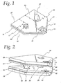
- FIG. 1 an optical format component 10 according to one embodiment of the present invention is shown.
- the optical format component 10 is capable of forming a reliable optical format, significantly increasing the production efficiency for optical testing instruments, and further increasing ease of testing.
- the optical format component 10 of FIG. 1 is designed to be joined with another optical format component to form an optical format.
- the optical format component 10 includes a read surface 12 upon which a sample is deposited for analysis.
- An inlet surface 14 extends outwardly from the read surface 12 and serves to direct sample fluid from outside an optical format toward the read surface 12.
- the read surface 12 and the inlet surface 14 may be formed within a format cavity 16. Slots 17 along the sides 18 and 19 of the optical format component 10 may ease handling and transportation of the optical format component 10.
- a hole 20 in the optical format component 10 is positioned to enable construction of an optical format when another optical format component is attached to the optical format component 10.
- a pin 22 projects from the inner surface 24 of the optical format component 10.
- the optical format component 10 forms an optical format when it is joined with an identical or substantially identical optical format component, which is inverted atop the optical format component 10.
- the centers of the hole 20 and the pin 22 are positioned a distance l b from a rear surface 27 of the format component and a distance l s from the side surfaces 25 and 29 of the format component.
- the pin 22 has a diameter dp and the hole 20 has a diameter d h .
- the diameter d h of the hole 20 and the diameter dp of the pin are approximately equal to assure a tight fit between pins and their corresponding holes when optical formats are constructed.
- Pins according to some embodiments of the present invention may be provided with vertical crush ribs to provide a tighter interference fit.
- the number of hole/pin combinations and their placement on format components 10 may be changed according to the desired size of the format components and the location of critical features of the format. It is preferred to provide enough hole/pin combinations to hold the format together for all post-assembly operations, such as packaging, shipping, and testing.
- the pin and hole features are not limited to cylindrical forms, but can be of many different cross-sectional shapes. An exploded view of an optical format formed when two format components are joined together is shown in FIG. 2 .
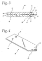
- a first optical format component 26 is shown in the process of being joined to a second optical format component 28 to form an optical format according to one embodiment of the present invention.
- the first optical format component 26 is provided with a first pin 30 and a first hole 32; likewise the second optical format 28 is provided with a second pin 34 and a second hole 36.
- the pins are provided with rounded tips, as shown on the second pin 34.
- the first and second optical format components 26 and 28 are moved together in the direction shown by arrow "A" of FIG. 2 .
- the first pin 30 is inserted into the second hole 36 and the second pin 34 is inserted into the first hole 32.
- a first read surface 38 and a second read surface 40 are separated from each other when the optical format is constructed to form a read area, where a sample is held during testing.
- the first optical format component 26 and the second optical format component 28 are made of optically clear or substantially optically clear material.
- a first optical window 42 (whose position is shown by the dotted line) provided on the lower surface of the first optical format component 26 of FIG.
- a second optical window 44 allow light to pass through the read area for optical testing of a sample within the read area 48 (shown in FIG. 3 ).
- the area of a first inner surface 49 of the first optical format component 26 is large in comparison to the area of the first read surface 38.
- the area of a second inner surface 51 of the second optical format component 28 is large in comparison to the area of the second read surface 40.
- the width w of the read area 48 is governed by the height difference between the first inner surface 49 and the first read surface 38 and further by the height difference between the second inner surface 51 and the second read surface 40.
- the interface between the first and second inner surfaces is free of connecting materials or connecting areas such as adhesives, sonic welding ribs, or other features that could potentially change the dimensions and tolerances of the capillary gap and optical read path of the format.
- the read area 48 may comprise a capillary gap holding the sample within the read area.
- a fill capillary gap 50 may be formed by a first inlet surface 52 and a second inlet surface 54.
- the first optical format component 26 and the second optical format component 28 are identical or substantially identical.
- the first and second optical format components may be held together by friction between the pins 30 and 34 and the holes 36 and 32. Additional or alternative connection techniques may be used to hold the pins and holes together.
- the pins 30 and 34 are sonically welded into the holes 36 and 32. Additionally or alternatively, the pins 30 and 34 and the holes 36 and 32 may be joined by adhesive at the pin-hole mating interface. It is preferred to assure that adhesive does not attach to the inner surfaces of the optical format components, as adhesive on these inner surfaces adversely affects the uniformity of optical path length in the construction of optical formats.
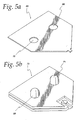
- FIG. 4 schematically shows an optical format component 56 according to one embodiment of the present invention featuring first and second pins 58 and 60 and first and second holes 62 and 64.
- a multiple-pin optical format component may be useful when a longer optical format component is desirable.
- the longer optical format 56 of FIG. 4 is easier for a user to handle than a shorter optical component.
- Optical formats according to some embodiments of the present invention may be manufactured using different types of optical format components.
- an optical format may be formed by a base component having pins and no holes, and a lid member having holes and no pins.
- FIG. 5a shows one embodiment of a lid component 66 having first and second holes 68 and 70 adapted to mate with first and second pins 69 and 71 on a base component 73, as shown in FIG. 5b .
- Lid and base components such as the lid component 66 and base component 73 may be formed by molding or by punching from clear plastic stock.
- Optical format components and optical formats according to the present invention may be manufactured using a number of manufacturing techniques and may be constructed of a variety of materials.
- Optical format components may be molded, embossed, coined, or manufactured using a combination of these processes, and may be constructed of materials such as acrylic, polycarbonate, and polyester.
- FIG. 6 a strip 70 of optical format components 72 is shown.
- the strip 70 has been formed by a continuous molding process employing first and second ribbons 74 and 76.
- Each of the optical format components 72 has been molded on the first and second ribbons 74 and 76 and these ribbons hold the optical format components in place.
- Slots 78 provided on the optical format components 72 are the result of removing the format in a post-molding operation. The slots have value for alignment of the format during processes such as packaging and inserting the format into a fmal diagnostic meter. Molding of the optical format components 72 may be accomplished by multi-cavity injection-molding, by which several optical format components 72 are molded at once.
- Optical format components 72 made by this process are held in one orientation until the components are removed from the ribbons 74 and 76.
- the ribbons 74 and 76 are made of Mylar TM and are provided with guide holes 80 for advancement along a production machine and slits 82 to allow easy removal of molded optical format components 72.
- optical format components 72 Following molding of the optical format components 72, chemical reagents as required in particular embodiments of optical formats according to the present invention may be applied to read surfaces 12 of the optical format components. Following deposition of the reagent, the reagent may be dried. Optical format components with reagent applied to read surfaces may next be mated with optical format components with or without reagent applied to their read surfaces, as shown in FIG. 7 .
- FIG. 7 shows a first strip 86 of optical format components being joined to a second strip 88 of optical format components.
- Either the first strip 86, the second strip 88, neither strip, or both strips of optical format components may be provided with reagent on their read surfaces 12.
- the first and second strips 86 and 88 of optical format components have substantially identical shapes, such that as the strips are moved in the direction shown by arrow "B," and approach each other, the optical format components will join together to result in optical formats.
- the optical format components may be sonically welded or connected via adhesives at the pin-hole interfaces at this point. Joined optical formats may be left on the strips to dispense as needed, or may be picked off the strips and placed into containers or wrapped individually.
- FIG. 8 shows a two-component chain 90 of optical format components 92.
- the optical format components 92 are joined to each other by links 94.
- Chains 90 of optical format components may be molded, reeled, and joined together similarly to the process described above with respect to FIG. 7 , including the deposition of reagent chemicals on the optical format components.
- optical formats formed as chains may be packaged in strips of several optical formats, wrapped and sold individually, or separated after formation and sold in containers holding multiple optical formats.
- optical format components are formed of optically clear or substantially optically clear materials.
- two optical format components such as the first and second optical format components 26 and 28 of FIGS. 2 and 3
- two optical format components are molded of optically clear or substantially optically clear materials
- light may pass directly through an optical format through optical windows and through the sample.
- a first optical format component may be clear and a second optical format component may be opaque.
- Such a construction may be used in measurements based on light reflectance or diffusion rather than light transmission.
- Optical formats according to the present invention may be packaged and sold as individual optical formats or packaged and sold as multiple formats on format strips.
Landscapes
- Chemical & Material Sciences (AREA)
- Health & Medical Sciences (AREA)
- General Health & Medical Sciences (AREA)
- Analytical Chemistry (AREA)
- Physics & Mathematics (AREA)
- General Physics & Mathematics (AREA)
- Clinical Laboratory Science (AREA)
- Chemical Kinetics & Catalysis (AREA)
- Dispersion Chemistry (AREA)
- Life Sciences & Earth Sciences (AREA)
- Biochemistry (AREA)
- Hematology (AREA)
- Immunology (AREA)
- Pathology (AREA)
- Optical Measuring Cells (AREA)
- Investigating Or Analysing Materials By Optical Means (AREA)
- Investigating Or Analysing Materials By The Use Of Chemical Reactions (AREA)
- Investigating Or Analysing Biological Materials (AREA)
Claims (22)
- Verfahren zur Ausbildung eines Formats für die optische Analyse einer Probe, umfassend:die Ausbildung einer ersten Formatkomponente (26), die einen ersten Formatkomponentenstift (30), ein erstes Formatkomponentenloch (32), eine erste Einlassoberfläche (52) und eine erste Leseoberfläche (38) umfasst;die Ausbildung einer zweiten Formatkomponente (28), die einen zweiten Formatkomponentenstift (34), ein zweites Formatkomponentenloch (36), eine zweite Einlassoberfläche (54) und eine zweite Leseoberfläche (40) umfasst;das Ausrichten der ersten und der zweiten Formatkomponente (26, 28), sodass die erste Einlassoberfläche (52) ungefähr mit der zweiten Einlassoberfläche (54) zur Ausbildung eines kapillaren Spalts ausgerichtet ist, und die erste Leseoberfläche (38) ungefähr mit der zweiten Leseoberfläche (40) ausgerichtet ist;das Einbringen des ersten Formatkomponentenstifts (30) in das zweite Formatkomponentenloch (36); unddas Einbringen des zweiten Formatkomponentenstifts (34) in das erste Formatkomponentenloch (32),dadurch gekennzeichnet, dass zumindest eines aus dem Ausbilden der ersten Formatkomponente (26) und dem Ausbilden der zweiten Formatkomponente (28) das Formen von Schlitzen (17) in die zumindest eine Komponente (26, 28) durch Formen der Formatkomponente (26, 28) zwischen einem ersten und einem zweiten Band (74, 76) umfasst.
- Verfahren nach Anspruch 1, weiters umfassend das Auftragen eines Reagens auf zumindest eine aus der ersten Leseoberfläche (38) und der zweiten Leseoberfläche (40).
- Verfahren nach Anspruch 1 oder 2, weiters umfassend das Auftragen eines Haftmittels auf zumindest eines aus dem ersten Formatkomponentenstift (30), dem ersten Formatkomponentenloch (32), dem zweiten Formatkomponentenstift (34) und dem zweiten Formatkomponentenloch (36).
- Verfahren nach Anspruch 1 oder 2, weiters umfassend Ultraschallschweißen zumindest eines aus dem ersten und zweiten Komponentenstift (30, 34) an sein entsprechendes Formatkomponentenloch (32, 36).
- Verfahren nach einem der Ansprüche 1 bis 4, worin zumindest eines aus dem Ausbilden der ersten Formatkomponente (26) und dem Ausbilden der zweiten Formatkomponente (28) das Formen der Formatkomponente (26, 28) zwischen dem ersten und dem zweiten Band (74, 76) umfasst.
- Verfahren nach einem der Ansprüche 1 bis 5, worin zumindest eines aus dem Ausbilden der ersten Formatkomponente (26) und dem Ausbilden der zweiten Formatkomponente (28) das Ausbilden der Komponente (26, 28) als Teil einer Kette von Formatkomponenten umfasst.
- Verfahren nach einem der Ansprüche 1 bis 6, worin die erste Formatkomponente (26) optisch transparent ist und weiters ein erstes optisches Fenster (42) umfasst, das ungefähr mit der ersten Leseoberfläche (38) ausgerichtet ist.
- Verfahren nach einem der Ansprüche 1 bis 6, worin die erste und die zweite Formatkomponente (26, 28) optisch transparent sind und worin die erste Formatkomponente (26) ein erstes optisches Fenster (42) umfasst, das ungefähr mit der ersten Leseoberfläche (38) ausgerichtet ist, und die zweite Formatkomponente (28) ein zweites optisches Fenster (44) umfasst, das ungefähr mit der zweiten Leseoberfläche (40) ausgerichtet ist.
- Format zur optischen Analyse einer Probe, umfassend:eine erste Formatkomponente (26) mit zumindest einem ersten Formatkomponentenstift (30), einer ersten Formatkomponenten-Innenoberfläche (49), einer ersten Einlassoberfläche (52) und einer ersten Leseoberfläche (38); undeine zweite Formatkomponente (28) mit zumindest einem zweiten Formatkomponentenloch (36), einer zweiten Formatkomponenten-Innenoberfläche (51), einer zweiten Einlassoberfläche (54) und einer zweiten Leseoberfläche (40);worin der erste Formatkomponentenstift (30) in das zweite Formatkomponentenloch (36) eingebracht wird,
die erste Formatkomponenten-Innenoberfläche (49) und die zweite Formatkomponenten-Innenoberfläche (51) an eine Innenoberflächengrenzfläche anstoßen, wobei die zweite Einlassoberfläche (54) und die erste Einlassoberfläche (52) ausgerichtet sind, um einen Kapillar-Spalt (50) zu bilden, und die erste Leseoberfläche (38) und die zweite Leseoberfläche (40) ausgerichtet sind, um ein Lesevolumen (48) zu bilden,
dadurch gekennzeichnet, dass auf einer ersten und einer zweiten Seitenoberfläche (18, 19) von zumindest einer aus der ersten oder der zweiten Formatkomponente (26, 28) Schlitze (17) ausgebildet sind. - Format nach Anspruch 9, worin das Lesevolumen (48) eine Breite b aufweist, die durch die Höhendifferenz zwischen der ersten Innenoberfläche (49) und der ersten Leseoberfläche (38) und durch die Höhendifferenz zwischen der zweiten Innenoberfläche (51) und der zweiten Leseoberfläche (40) bestimmt ist.
- Format nach Anspruch 9 oder 10, worin ein Reagens auf zumindest aus der ersten Leseoberfläche (38) und der zweiten Leseoberfläche (40) aufgebracht ist.
- Format nach einem der Ansprüche 9 bis 11, worin die erste Formatkomponenten-Innenoberfläche (49) und die zweite Formatkomponenten-Innenoberfläche (51) im Wesentlichen vollständig aneinander anstoßen und die InnenoberflächenGrenzfläche im Wesentlichen frei von Haftmitteln oder einem anderen störenden Material ist.
- Format nach einem der Ansprüche 9 bis 12, worin die erste Leseoberfläche (38) und die erste Einlassoberfläche (52) innerhalb eines ersten Formatkomponentenhohlraums angeordnet sind und die zweite Leseoberfläche (40) und die zweite Einlassoberfläche (54) innerhalb eines zweiten Formatkomponentenhohlraums angeordnet sind.
- Format nach einem der Ansprüche 9 bis 13, worin die erste Formatkomponente (26) optisch transparent ist und ein erstes optisches Fenster (42) umfasst, das mit der ersten Leseoberfläche (38) ausgerichtet ist.
- Format nach einem der Ansprüche 9 bis 13, worin die erste und die zweite Formatkomponente (26, 28) optisch transparent sind oder im Wesentlichen optisch transparent sind.
- Format nach Anspruch 15, worin die erste Formatkomponente (26) weiters eine erste Formatkomponenten-Außenoberfläche umfasst und die zweite Formatkomponente (28) weiters eine zweite Formatkomponenten-Außenoberfläche umfasst, wobei die erste Formatkomponente (26) ein erstes optisches Fenster (42) umfasst, das auf der ersten Formatkomponenten-Außenoberfläche angeordnet ist und ungefähr mit der ersten Leseoberfläche (38) ausgerichtet ist, und die zweite Formatkomponente (28) ein zweites optisches Fenster (44) aufweist, das auf der zweiten Formatkomponenten-Außenoberfläche angeordnet ist und ungefähr mit der zweiten Leseoberfläche (40) ausgerichtet ist, wobei das erste optische Fenster (42), das Lesevolumen (48) und das zweite optische Fenster (44) ausgerichtet sind, um einen optischen Strahlengang zu bilden.
- Format nach einem der Ansprüche 9 bis 16, worin die zweite Formatkomponente (28) einen ersten und einen zweiten Komponentenschlitz (17) umfasst, der auf der ersten und der zweiten Seitenoberfläche (18, 19) der zweiten optischen Komponente (28) angeordnet ist.
- Format nach einem der Ansprüche 9 bis 17, worin der zumindest eine erste Formatkomponentenstift (30) an dem zumindest einen zweiten Formatkomponentenloch (36) haftend angebracht ist.
- Format nach einem der Ansprüche 9 bis 17, worin der zumindest eine erste Formatkomponentenstift (30) in das zumindest eine zweite Formatkomponentenloch (36) ultraschallgeschweißt ist.
- Format nach einem der Ansprüche 9 bis 19, worin die zweite Formatkomponente (28) ungefähr mit der ersten Formatkomponente (26) identisch ist.
- Format nach einem der Ansprüche 9 bis 20, worin die erste Formatkomponente (26) weiters zumindest ein erstes Formatkomponentenloch (32) umfasst und die zweite Formatkomponente (28) weiters zumindest einen zweiten Formatkomponentenstift (34) umfasst.
- Format nach Anspruch 21, worin die erste und die zweite Formatkomponente (26, 28) durch Reibung zwischen miteinander fluchtend ausgerichteten Paaren von Löchern (32, 36) und Stiften (30, 34) zusammengehalten sind, die eine Grenzfläche zwischen der ersten Formatkomponenten-Innenoberfläche (49) und der zweiten Formatkomponenten-Innenformatoberfläche (51) bilden.
Priority Applications (1)
| Application Number | Priority Date | Filing Date | Title |
|---|---|---|---|
| EP08009065A EP1956359A1 (de) | 2003-10-30 | 2004-10-29 | Formate für die optische Analyse sowie Verfahren zur Herstellung davon |
Applications Claiming Priority (2)
| Application Number | Priority Date | Filing Date | Title |
|---|---|---|---|
| US51533703P | 2003-10-30 | 2003-10-30 | |
| PCT/US2004/036086 WO2005043133A1 (en) | 2003-10-30 | 2004-10-29 | Formats for optical analysis and methods of manufacturing the same |
Related Child Applications (1)
| Application Number | Title | Priority Date | Filing Date |
|---|---|---|---|
| EP08009065A Division EP1956359A1 (de) | 2003-10-30 | 2004-10-29 | Formate für die optische Analyse sowie Verfahren zur Herstellung davon |
Publications (2)
| Publication Number | Publication Date |
|---|---|
| EP1685385A1 EP1685385A1 (de) | 2006-08-02 |
| EP1685385B1 true EP1685385B1 (de) | 2009-04-15 |
Family
ID=34549392
Family Applications (2)
| Application Number | Title | Priority Date | Filing Date |
|---|---|---|---|
| EP08009065A Ceased EP1956359A1 (de) | 2003-10-30 | 2004-10-29 | Formate für die optische Analyse sowie Verfahren zur Herstellung davon |
| EP04796799A Expired - Lifetime EP1685385B1 (de) | 2003-10-30 | 2004-10-29 | Formate für die optische analyse sowie verfahren zur herstellung davon |
Family Applications Before (1)
| Application Number | Title | Priority Date | Filing Date |
|---|---|---|---|
| EP08009065A Ceased EP1956359A1 (de) | 2003-10-30 | 2004-10-29 | Formate für die optische Analyse sowie Verfahren zur Herstellung davon |
Country Status (16)
| Country | Link |
|---|---|
| US (2) | US7494620B2 (de) |
| EP (2) | EP1956359A1 (de) |
| JP (1) | JP2007510163A (de) |
| KR (1) | KR100764644B1 (de) |
| CN (1) | CN1875260A (de) |
| AT (1) | ATE428916T1 (de) |
| AU (1) | AU2004285233A1 (de) |
| CA (1) | CA2539493A1 (de) |
| DE (1) | DE602004020652D1 (de) |
| DK (1) | DK1685385T3 (de) |
| ES (1) | ES2322855T3 (de) |
| IL (1) | IL174946A0 (de) |
| NO (1) | NO20062456L (de) |
| RU (1) | RU2006118710A (de) |
| WO (1) | WO2005043133A1 (de) |
| ZA (1) | ZA200603282B (de) |
Families Citing this family (3)
| Publication number | Priority date | Publication date | Assignee | Title |
|---|---|---|---|---|
| USD587142S1 (en) | 2006-12-22 | 2009-02-24 | Abbott Diabetes Care Inc. | Sensors |
| US7802467B2 (en) | 2006-12-22 | 2010-09-28 | Abbott Diabetes Care Inc. | Analyte sensors and methods of use |
| USD766457S1 (en) * | 2014-08-20 | 2016-09-13 | Neurotar Ltd | Medical instrument, instrument and tool for laboratory use |
Family Cites Families (18)
| Publication number | Priority date | Publication date | Assignee | Title |
|---|---|---|---|---|
| US4756884A (en) * | 1985-08-05 | 1988-07-12 | Biotrack, Inc. | Capillary flow device |
| DK163194C (da) * | 1988-12-22 | 1992-06-22 | Radiometer As | Fremgangsmaade ved fotometrisk in vitro bestemmelse af en blodgasparameter i en blodproeve |
| US5564419A (en) * | 1987-11-25 | 1996-10-15 | Radiometer A/S | Method of photometric in vitro determination of the content of oxygen in a blood sample |
| US5148596A (en) | 1989-09-19 | 1992-09-22 | Autosplice, Inc. | Continuous molded electronic component assembly |
| ATE133297T1 (de) | 1989-09-19 | 1996-02-15 | Autosplice Inc | Anordnung von kontinuierlich eingebetteten elektronischen bauelementen |
| US5035494A (en) * | 1990-03-01 | 1991-07-30 | V-Tech, Inc. | Molded plastic article assembly means |
| US5371020A (en) * | 1991-09-19 | 1994-12-06 | Radiometer A/S | Method of photometric in vitro determination of the content of an analyte in a sample |
| US5616053A (en) | 1995-07-05 | 1997-04-01 | Auto Splice Systems, Inc. | Continuous molded electrical connector |
| US5957725A (en) | 1995-07-05 | 1999-09-28 | Auto Splice Systems Inc. | Continuous molded plastic components or assemblies |
| US5706952A (en) | 1996-01-11 | 1998-01-13 | Autosplice Systems Inc. | Continuous carrier for electrical or mechanical components |
| US5957739A (en) | 1996-01-11 | 1999-09-28 | Autosplice Systems Inc. | Continuous electronic stamping with offset carrier |
| US5749458A (en) | 1996-02-23 | 1998-05-12 | Auto Splice Systems, Inc. | Miniature jumper switch with wire contact maker |
| US6202853B1 (en) | 1996-01-11 | 2001-03-20 | Autosplice Systems, Inc. | Secondary processing for electrical or mechanical components molded to continuous carrier supports |
| US5620086A (en) | 1996-02-23 | 1997-04-15 | Autosplice Systems, Inc. | Miniature jumper switch |
| US6123820A (en) * | 1998-06-05 | 2000-09-26 | Grupo Ch-Werfen, S.A. | Sensor cartridges |
| DE60022025T2 (de) * | 1999-05-28 | 2006-06-29 | Cepheid, Sunnyvale | Anlage zum brechen von zellen |
| CA2697026A1 (en) * | 2000-12-12 | 2002-06-12 | Bayer Healthcare Llc | Method of making a capillary channel |
| FR2835617B1 (fr) * | 2002-02-01 | 2004-04-30 | Junior Instruments | Dispositif d'entrainement d'une bande de cuvettes dans un appareil d'analyse |
-
2004
- 2004-10-29 DE DE602004020652T patent/DE602004020652D1/de not_active Expired - Lifetime
- 2004-10-29 AU AU2004285233A patent/AU2004285233A1/en not_active Abandoned
- 2004-10-29 RU RU2006118710/28A patent/RU2006118710A/ru not_active Application Discontinuation
- 2004-10-29 CN CNA2004800322122A patent/CN1875260A/zh active Pending
- 2004-10-29 DK DK04796799T patent/DK1685385T3/da active
- 2004-10-29 KR KR1020067006864A patent/KR100764644B1/ko not_active Expired - Fee Related
- 2004-10-29 WO PCT/US2004/036086 patent/WO2005043133A1/en not_active Ceased
- 2004-10-29 US US10/576,992 patent/US7494620B2/en not_active Expired - Fee Related
- 2004-10-29 EP EP08009065A patent/EP1956359A1/de not_active Ceased
- 2004-10-29 JP JP2006538337A patent/JP2007510163A/ja not_active Withdrawn
- 2004-10-29 EP EP04796799A patent/EP1685385B1/de not_active Expired - Lifetime
- 2004-10-29 AT AT04796799T patent/ATE428916T1/de not_active IP Right Cessation
- 2004-10-29 CA CA002539493A patent/CA2539493A1/en not_active Abandoned
- 2004-10-29 ES ES04796799T patent/ES2322855T3/es not_active Expired - Lifetime
-
2006
- 2006-04-11 IL IL174946A patent/IL174946A0/en unknown
- 2006-04-25 ZA ZA200603282A patent/ZA200603282B/en unknown
- 2006-05-30 NO NO20062456A patent/NO20062456L/no not_active Application Discontinuation
-
2008
- 2008-10-15 US US12/252,133 patent/US7731897B2/en not_active Expired - Fee Related
Also Published As
| Publication number | Publication date |
|---|---|
| ES2322855T3 (es) | 2009-06-30 |
| CN1875260A (zh) | 2006-12-06 |
| IL174946A0 (en) | 2006-08-20 |
| EP1956359A1 (de) | 2008-08-13 |
| KR20060085678A (ko) | 2006-07-27 |
| KR100764644B1 (ko) | 2007-10-09 |
| DK1685385T3 (da) | 2009-07-20 |
| NO20062456L (no) | 2006-05-30 |
| AU2004285233A1 (en) | 2005-05-12 |
| EP1685385A1 (de) | 2006-08-02 |
| JP2007510163A (ja) | 2007-04-19 |
| US7494620B2 (en) | 2009-02-24 |
| WO2005043133A1 (en) | 2005-05-12 |
| ZA200603282B (en) | 2007-07-25 |
| RU2006118710A (ru) | 2007-12-10 |
| US7731897B2 (en) | 2010-06-08 |
| DE602004020652D1 (de) | 2009-05-28 |
| CA2539493A1 (en) | 2005-05-12 |
| US20090040515A1 (en) | 2009-02-12 |
| ATE428916T1 (de) | 2009-05-15 |
| US20070031975A1 (en) | 2007-02-08 |
Similar Documents
| Publication | Publication Date | Title |
|---|---|---|
| US10406523B2 (en) | Integrated cartridge housings for sample analysis | |
| JP5744906B2 (ja) | 試料分析用の一体型ヒンジ式カートリッジ・ハウジング | |
| EP2962104B1 (de) | Lateral-flow-testgerät mit teststreifenhalter | |
| WO1983000296A1 (en) | Cuvette system for automated chemical analyzer | |
| US7731897B2 (en) | Formats for optical analysis and methods of manufacturing the same | |
| CA2465157C (en) | Sample well strip | |
| MXPA06004808A (es) | Formatos para analisis optico y metodo de manufactura de los mismos | |
| HK1100187A (en) | Formats for optical analysis and methods of manufacturing the same | |
| CA2542897A1 (en) | Optical cuvette with platform-and-well construction | |
| CN1378880A (zh) | 与注意点成套测试工具一起使用的壁式适配器 |
Legal Events
| Date | Code | Title | Description |
|---|---|---|---|
| PUAI | Public reference made under article 153(3) epc to a published international application that has entered the european phase |
Free format text: ORIGINAL CODE: 0009012 |
|
| 17P | Request for examination filed |
Effective date: 20060530 |
|
| AK | Designated contracting states |
Kind code of ref document: A1 Designated state(s): AT BE BG CH CY CZ DE DK EE ES FI FR GB GR HU IE IT LI LU MC NL PL PT RO SE SI SK TR |
|
| AX | Request for extension of the european patent |
Extension state: HR LT |
|
| 17Q | First examination report despatched |
Effective date: 20061124 |
|
| RAX | Requested extension states of the european patent have changed |
Extension state: LT Payment date: 20060530 Extension state: HR Payment date: 20060530 |
|
| GRAP | Despatch of communication of intention to grant a patent |
Free format text: ORIGINAL CODE: EPIDOSNIGR1 |
|
| GRAP | Despatch of communication of intention to grant a patent |
Free format text: ORIGINAL CODE: EPIDOSNIGR1 |
|
| GRAS | Grant fee paid |
Free format text: ORIGINAL CODE: EPIDOSNIGR3 |
|
| GRAA | (expected) grant |
Free format text: ORIGINAL CODE: 0009210 |
|
| RAP1 | Party data changed (applicant data changed or rights of an application transferred) |
Owner name: BAYER HEALTHCARE LLC |
|
| AK | Designated contracting states |
Kind code of ref document: B1 Designated state(s): AT BE BG CH CY CZ DE DK EE ES FI FR GB GR HU IE IT LI LU MC NL PL PT RO SE SI SK TR |
|
| AX | Request for extension of the european patent |
Extension state: HR LT |
|
| REG | Reference to a national code |
Ref country code: CH Ref legal event code: EP Ref country code: GB Ref legal event code: FG4D |
|
| REG | Reference to a national code |
Ref country code: IE Ref legal event code: FG4D |
|
| REF | Corresponds to: |
Ref document number: 602004020652 Country of ref document: DE Date of ref document: 20090528 Kind code of ref document: P |
|
| REG | Reference to a national code |
Ref country code: CH Ref legal event code: NV Representative=s name: E. BLUM & CO. AG PATENT- UND MARKENANWAELTE VSP |
|
| REG | Reference to a national code |
Ref country code: SE Ref legal event code: TRGR |
|
| REG | Reference to a national code |
Ref country code: ES Ref legal event code: FG2A Ref document number: 2322855 Country of ref document: ES Kind code of ref document: T3 |
|
| REG | Reference to a national code |
Ref country code: DK Ref legal event code: T3 |
|
| LTIE | Lt: invalidation of european patent or patent extension |
Effective date: 20090415 |
|
| NLV1 | Nl: lapsed or annulled due to failure to fulfill the requirements of art. 29p and 29m of the patents act | ||
| PG25 | Lapsed in a contracting state [announced via postgrant information from national office to epo] |
Ref country code: PT Free format text: LAPSE BECAUSE OF FAILURE TO SUBMIT A TRANSLATION OF THE DESCRIPTION OR TO PAY THE FEE WITHIN THE PRESCRIBED TIME-LIMIT Effective date: 20090915 Ref country code: AT Free format text: LAPSE BECAUSE OF FAILURE TO SUBMIT A TRANSLATION OF THE DESCRIPTION OR TO PAY THE FEE WITHIN THE PRESCRIBED TIME-LIMIT Effective date: 20090415 |
|
| PG25 | Lapsed in a contracting state [announced via postgrant information from national office to epo] |
Ref country code: SI Free format text: LAPSE BECAUSE OF FAILURE TO SUBMIT A TRANSLATION OF THE DESCRIPTION OR TO PAY THE FEE WITHIN THE PRESCRIBED TIME-LIMIT Effective date: 20090415 Ref country code: PL Free format text: LAPSE BECAUSE OF FAILURE TO SUBMIT A TRANSLATION OF THE DESCRIPTION OR TO PAY THE FEE WITHIN THE PRESCRIBED TIME-LIMIT Effective date: 20090415 Ref country code: NL Free format text: LAPSE BECAUSE OF FAILURE TO SUBMIT A TRANSLATION OF THE DESCRIPTION OR TO PAY THE FEE WITHIN THE PRESCRIBED TIME-LIMIT Effective date: 20090415 |
|
| PG25 | Lapsed in a contracting state [announced via postgrant information from national office to epo] |
Ref country code: RO Free format text: LAPSE BECAUSE OF FAILURE TO SUBMIT A TRANSLATION OF THE DESCRIPTION OR TO PAY THE FEE WITHIN THE PRESCRIBED TIME-LIMIT Effective date: 20090415 Ref country code: EE Free format text: LAPSE BECAUSE OF FAILURE TO SUBMIT A TRANSLATION OF THE DESCRIPTION OR TO PAY THE FEE WITHIN THE PRESCRIBED TIME-LIMIT Effective date: 20090415 Ref country code: CZ Free format text: LAPSE BECAUSE OF FAILURE TO SUBMIT A TRANSLATION OF THE DESCRIPTION OR TO PAY THE FEE WITHIN THE PRESCRIBED TIME-LIMIT Effective date: 20090415 |
|
| PLBE | No opposition filed within time limit |
Free format text: ORIGINAL CODE: 0009261 |
|
| STAA | Information on the status of an ep patent application or granted ep patent |
Free format text: STATUS: NO OPPOSITION FILED WITHIN TIME LIMIT |
|
| PG25 | Lapsed in a contracting state [announced via postgrant information from national office to epo] |
Ref country code: SK Free format text: LAPSE BECAUSE OF FAILURE TO SUBMIT A TRANSLATION OF THE DESCRIPTION OR TO PAY THE FEE WITHIN THE PRESCRIBED TIME-LIMIT Effective date: 20090415 Ref country code: BE Free format text: LAPSE BECAUSE OF FAILURE TO SUBMIT A TRANSLATION OF THE DESCRIPTION OR TO PAY THE FEE WITHIN THE PRESCRIBED TIME-LIMIT Effective date: 20090415 |
|
| 26N | No opposition filed |
Effective date: 20100118 |
|
| PG25 | Lapsed in a contracting state [announced via postgrant information from national office to epo] |
Ref country code: BG Free format text: LAPSE BECAUSE OF FAILURE TO SUBMIT A TRANSLATION OF THE DESCRIPTION OR TO PAY THE FEE WITHIN THE PRESCRIBED TIME-LIMIT Effective date: 20090715 |
|
| PG25 | Lapsed in a contracting state [announced via postgrant information from national office to epo] |
Ref country code: MC Free format text: LAPSE BECAUSE OF NON-PAYMENT OF DUE FEES Effective date: 20091031 |
|
| REG | Reference to a national code |
Ref country code: CH Ref legal event code: PL |
|
| REG | Reference to a national code |
Ref country code: DK Ref legal event code: EBP |
|
| PG25 | Lapsed in a contracting state [announced via postgrant information from national office to epo] |
Ref country code: LI Free format text: LAPSE BECAUSE OF NON-PAYMENT OF DUE FEES Effective date: 20091031 Ref country code: IE Free format text: LAPSE BECAUSE OF NON-PAYMENT OF DUE FEES Effective date: 20091029 Ref country code: GR Free format text: LAPSE BECAUSE OF FAILURE TO SUBMIT A TRANSLATION OF THE DESCRIPTION OR TO PAY THE FEE WITHIN THE PRESCRIBED TIME-LIMIT Effective date: 20090716 Ref country code: CH Free format text: LAPSE BECAUSE OF NON-PAYMENT OF DUE FEES Effective date: 20091031 |
|
| PG25 | Lapsed in a contracting state [announced via postgrant information from national office to epo] |
Ref country code: GB Free format text: LAPSE BECAUSE OF NON-PAYMENT OF DUE FEES Effective date: 20091029 |
|
| PG25 | Lapsed in a contracting state [announced via postgrant information from national office to epo] |
Ref country code: DK Free format text: LAPSE BECAUSE OF NON-PAYMENT OF DUE FEES Effective date: 20091031 |
|
| PG25 | Lapsed in a contracting state [announced via postgrant information from national office to epo] |
Ref country code: IT Free format text: LAPSE BECAUSE OF NON-PAYMENT OF DUE FEES Effective date: 20091029 |
|
| PG25 | Lapsed in a contracting state [announced via postgrant information from national office to epo] |
Ref country code: LU Free format text: LAPSE BECAUSE OF NON-PAYMENT OF DUE FEES Effective date: 20091029 |
|
| PG25 | Lapsed in a contracting state [announced via postgrant information from national office to epo] |
Ref country code: HU Free format text: LAPSE BECAUSE OF FAILURE TO SUBMIT A TRANSLATION OF THE DESCRIPTION OR TO PAY THE FEE WITHIN THE PRESCRIBED TIME-LIMIT Effective date: 20091016 |
|
| PG25 | Lapsed in a contracting state [announced via postgrant information from national office to epo] |
Ref country code: TR Free format text: LAPSE BECAUSE OF FAILURE TO SUBMIT A TRANSLATION OF THE DESCRIPTION OR TO PAY THE FEE WITHIN THE PRESCRIBED TIME-LIMIT Effective date: 20090415 |
|
| PG25 | Lapsed in a contracting state [announced via postgrant information from national office to epo] |
Ref country code: CY Free format text: LAPSE BECAUSE OF FAILURE TO SUBMIT A TRANSLATION OF THE DESCRIPTION OR TO PAY THE FEE WITHIN THE PRESCRIBED TIME-LIMIT Effective date: 20090415 |
|
| REG | Reference to a national code |
Ref country code: FR Ref legal event code: PLFP Year of fee payment: 12 |
|
| PGFP | Annual fee paid to national office [announced via postgrant information from national office to epo] |
Ref country code: FI Payment date: 20151028 Year of fee payment: 12 |
|
| PGFP | Annual fee paid to national office [announced via postgrant information from national office to epo] |
Ref country code: ES Payment date: 20151026 Year of fee payment: 12 Ref country code: FR Payment date: 20151019 Year of fee payment: 12 Ref country code: SE Payment date: 20151028 Year of fee payment: 12 |
|
| REG | Reference to a national code |
Ref country code: FR Ref legal event code: ST Effective date: 20170630 |
|
| PG25 | Lapsed in a contracting state [announced via postgrant information from national office to epo] |
Ref country code: FR Free format text: LAPSE BECAUSE OF NON-PAYMENT OF DUE FEES Effective date: 20161102 Ref country code: FI Free format text: LAPSE BECAUSE OF NON-PAYMENT OF DUE FEES Effective date: 20161029 |
|
| PG25 | Lapsed in a contracting state [announced via postgrant information from national office to epo] |
Ref country code: SE Free format text: LAPSE BECAUSE OF NON-PAYMENT OF DUE FEES Effective date: 20161030 |
|
| PG25 | Lapsed in a contracting state [announced via postgrant information from national office to epo] |
Ref country code: ES Free format text: LAPSE BECAUSE OF NON-PAYMENT OF DUE FEES Effective date: 20161030 |
|
| REG | Reference to a national code |
Ref country code: ES Ref legal event code: FD2A Effective date: 20181122 |
|
| PGFP | Annual fee paid to national office [announced via postgrant information from national office to epo] |
Ref country code: DE Payment date: 20211027 Year of fee payment: 18 |
|
| REG | Reference to a national code |
Ref country code: DE Ref legal event code: R119 Ref document number: 602004020652 Country of ref document: DE |
|
| PG25 | Lapsed in a contracting state [announced via postgrant information from national office to epo] |
Ref country code: DE Free format text: LAPSE BECAUSE OF NON-PAYMENT OF DUE FEES Effective date: 20230503 |