EP1685755B1 - Dispositif de recolte automoteur - Google Patents
Dispositif de recolte automoteur Download PDFInfo
- Publication number
- EP1685755B1 EP1685755B1 EP06001485.9A EP06001485A EP1685755B1 EP 1685755 B1 EP1685755 B1 EP 1685755B1 EP 06001485 A EP06001485 A EP 06001485A EP 1685755 B1 EP1685755 B1 EP 1685755B1
- Authority
- EP
- European Patent Office
- Prior art keywords
- harvester
- harvesting device
- self
- parts
- travelling
- Prior art date
- Legal status (The legal status is an assumption and is not a legal conclusion. Google has not performed a legal analysis and makes no representation as to the accuracy of the status listed.)
- Expired - Lifetime
Links
Images


Classifications
-
- A—HUMAN NECESSITIES
- A01—AGRICULTURE; FORESTRY; ANIMAL HUSBANDRY; HUNTING; TRAPPING; FISHING
- A01D—HARVESTING; MOWING
- A01D41/00—Combines, i.e. harvesters or mowers combined with threshing devices
- A01D41/12—Details of combines
- A01D41/14—Mowing tables
- A01D41/144—Foldable headers
Definitions
- the invention relates to a self-propelled agricultural harvester according to the preamble of claim 1, which comprises a harvester that, in particular by its design and flexibility significantly increases the efficiency of the harvester.
- Harvesting machines of the aforementioned type are available in numerous embodiments, preferably these are harvesting machines with a harvesting header for harvesting stalk-like crops such as corn or the like. Performance and speed are demands that need to be constantly improved. However, increasing the working widths of the attachments, which are made possible by ever greater engine power of the harvesting machines and thus increase the performance of the harvester, but require more and more complex solutions in terms of handling and transport.
- the Applicant discloses a harvester with a centrally divided harvester in which the two halves can be pivoted from a working position parallel to the ground into a vertical transport position.
- a harvesting device has been created by simple means, which offers a large working width with low weight and design effort, taking into account the aforementioned legal provisions.
- the requirement for even greater working widths however, set a limit in this embodiment by the legally permissible transport height.
- the visual obstruction is reduced by the cleverly arranged in the transport position harvester halves by the clever arrangement of the pivot axes to a minimum, but not completely avoided.
- a harvesting attachment for a combine harvester which consists of a fixedly connected to the combine center part and two pivotally hinged thereto side parts.
- the side parts take a subsequent to the expansion of the central part, aligned approximately parallel to the ground position, from which they can be transferred for transport on the road by a pivoting movement about an axis directed in the direction of travel in a transport position, in the the side parts rest with their top side by side on top of the middle part. It follows that the working width of the side parts can correspond to a maximum of half the working width of the middle part.
- both the side parts and the middle part in series are assigned divider tips with associated conveyors, which allow only a promotion of the crop in a direction of travel in the opposite direction. With this harvester so no directed transversely to the direction of travel, row-independent and a central intake inflowing promotion is reached.
- the invention is therefore an object of the invention to improve a generic self-propelled agricultural harvester such that when transporting with cultivated harvester, which has a working width of at least approximately three times the transport width and is particularly light and simple in construction, while complying with all legal provisions, especially with regard to the transport dimensions, the field of vision of the driver is not restricted by the harvesting device.
- a self-propelled agricultural harvester with a front in the travel and / or working direction arranged in front of a driver's station, at least formed of a central part and side panels and aligned in its longest orientation transversely to the direction of travel and working harvester, which is designed in that, as a result of an approximately 180 degree pivoting movement of at least two side parts of the harvesting device about pivot axes lying in at least approximately in the direction of travel and working direction, these side parts can be transferred from a position transverse to the travel and working direction into a transport position such that they are suitable for road travel the harvester legally permissible dimensions, in particular with respect to transport width are met and the at least two pivotable side parts whose transversely directed to the travel and working direction longitudinal extent in each case at least ann Hernd the maximum allowable transport width, are stored by adhering to a follow-up sequence in the pivoting after pivoting each other on the middle part with its underside upwards, each part of the harvester at least one mowing and /
- the side parts may have a width which corresponds approximately to the width of the middle part and thus the transport width. This means that the total working width is approximately three times the transport width.
- the wide version of the side parts of the harvester of a harvester according to the invention is made possible by the skillful vertically offset arrangement of the pivot axes of the side parts and by observing a follow-up sequence in the pivoting of the side parts after pivoting on top of each other on the middle part with its bottom above are at least approximately parallel to each other.
- the pivot axes of the side parts according to the invention are not exactly parallel to an imaginary vertical center plane of the harvester.
- the side parts pivot such that protruding components of harvesting equipment parts do not collide with other components during pivoting and intervene in the final transport position in existing open spaces.
- a harvesting device thus brought into transport position is so compact in the overall height that the field of vision of the driver of the harvesting machine is not restricted by the harvesting device. This benefits not only the overview and the ride comfort but in particular the traffic safety.
- Another major advantage of the invention lies in the compact dimensions and low weight of the harvesting device. These features significantly improve drivability due to the low center of gravity and a short distance to the front of the harvester, especially at high speeds on the road.
- a harvester with more than three parts which forms a package with four or more layers of harvester sections after pivoting into the transport position using the features according to the invention.
- the inventive design of the harvesting device and in particular by the inventive arrangement of the pivot axes of the side parts it is possible to operate the harvester by pivoting one or both sides of the harvester in a vertical inoperative position with different working widths without changing the harvesting device.
- These different operating positions open up completely new ways of working for the machine operator. It is thus possible, for example, to harvest a region at the beginning of the field only with the middle part of the harvesting device, which then makes it possible to completely unfold the harvesting device in the field without loss of crop. Especially for harvesters with a large working width a complete unfolding outside the field is often not possible, which is why then crop losses had to be taken by driving in and out in the crop in purchasing.
- the working width of the middle harvesting device part is in the inoperative position located side pieces tuned to a standardized row spacing of the crop so that a safe harvest of a number of rows is guaranteed, so the other rows of crops are neither damaged by parts of the harvester nor by the harvester itself or demolished.
- a harvesting machine is provided by the particularly advantageous features of the invention, which comprises a very flexible harvester with an increased working width, which represents no visual impairment of the driver in the transport position and significantly increases the traffic safety during transport.
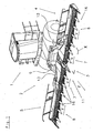
- FIG. 1 An example of a self-propelled agricultural harvester 1 in the embodiment of a forage harvester with a harvester 2, which is used in particular as an attachment for row-independent harvesting of stalk-like crop such as corn or the like, is in Fig. 1 illustrated and preferably consists, as shown here, of three parts 3, 4, 5.
- a fixedly connected via a base frame 6 with the harvester middle part 3 are assigned at the edge of this on each pivot axis 12, 13 hinged side panels 4, 5 ,
- the side parts 4, 5 supported in a manner not described laterally on the middle part 3 and locked if necessary.
- the middle part 3, as well as the side parts 4, 5 each include mowing and conveying means 7, 8, which circumferentially driven the crop with outwardly facing cutting and holding elements 9, 10 separate, record and promote further.
- the drive of the mowing and conveying means 7, 8 takes place in a manner not shown via drive trains from a power source of the connected harvester 1.
- the drive trains of the side parts 4, 5 are separated and vice versa when pivoting the side parts 4, 5 automatically reconnected in their working and operating position.
- the harvesting device 2 is pre-assembled exactly in the middle of the harvester 1, so that it extends symmetrically to a vertical longitudinal center plane of the harvester 1 to both sides.
- the middle part of the harvesting device 2 is equipped with two mowing and conveying means 7, which rotates in the opposite direction in the direction of arrow V the crop of the harvesting machine 1 respectively.
- the side parts 4, 5 of the harvester 2 of the harvesting machine 1 of the embodiment are advantageously each equipped with only one mowing and conveying means 8, which in the direction of arrow V driven circumferentially during the working cycle of the harvester, the entire harvestable crop of him exclusively on his in the direction of travel F. separating front side, absorbs and further promotes.
- the advantages of an embodiment of the side parts 4, 5 with only one mowing and conveying means 8 are the particularly low weight, the very compact size and thus the favorable center of gravity and the drive technology simple design. Especially with ever larger working widths of the harvesting devices are the important criteria that affect the production price, handling and transport options of the harvesting device crucial.
- the very short design of a harvesting device 2 of the example brings already in the Fig. 1 shown working position advantages with respect to short paths of the crop to the catchment area 11 of the harvester 1 and a favorable axle load distribution of the harvester.
- the in the Fig. 2 illustrated transport position of the harvesting device makes even more very advantageous features clear. From a working position of the harvesting device 2 according to Fig.
- the side part 5 is pivoted about the lower pivot axis 13 by 180 degrees, so that it is then placed with the underside facing upward on the middle part 3.
- the oblique orientation of the pivot axis causes the side member 5 as close as possible to the middle part 3 spaced on this can be stored without colliding with other components of the harvester 2.
- the second side part 4 also the pivoting 180 degrees, but to the much higher, but also for the same reasons obliquely arranged pivot axis 12, the high arrangement of the pivot axis 12 causes the side member 4 with its underside facing upward on the already pivoted side part 5 stores in transport position.
- slightly offset orientation of the harvesting equipment parts 3, 4, 5 in the transport position to each other is in Fig. 2 can be seen by the lines a, b and c, which serve as extensions of the front lines of the harvesting equipment parts 3, 4, 5 only for clarity.
- the advantageous transport position of the harvesting device 2 of the harvesting machine according to the invention is on in Fig. 2 illustrated embodiment particularly clear.
- the harvester 2 with a working width of almost three times the harvester width forms such a compact unit in its transport position that it does not adversely affect the driving characteristics when it is left in front of the harvester 1 during the transport journey due to its low weight and the low center of gravity that is close to the harvester Furthermore, it does not restrict the driver's field of vision and thus significantly improves traffic safety.
- the harvesting machine 1 according to the invention can by the advantageous design of his harvester 2 except in the in Fig. 1 and Fig. 2 shown operating modes are still operated in other advantageous modes.
- the mowing and conveying means 7, 8 primarily, as in particular in the detailed view of Fig. 3 recognizable, hingedly interconnected sub-segments 14 with arranged at this outwardly facing cutting and holding elements 9, 10, which lie in superimposed planes E1, E2, E3.
- Each sub-segment 14 has in each case in the lower plane E1 a cutting element 9, in the middle plane E2 each have a holding element 10 and in the upper level E3 also only one further holding element 10.
- the articulated interconnected sub-segments 14 of the mowing and conveying means 7, 8 are driven in rotation around at least two drive and deflection wheels not shown so that they separate the crop with their running in the direction of travel and forward F running, record and in the art an endless conveyor linearly in the direction of arrow V to the center of the harvester 2 promote.
- a critical point of the promotion is the trouble-free and loss-free transfer of the crop at the interfaces between the middle part 3 and side panels 4, 5. In these areas, the entire previously taken up by the mowing and conveying means 8 and promoted crop to the inside Mowing and conveying 7 handed over the respective harvester side and are absorbed by this, while simultaneously separating and picking up further crop.
Landscapes
- Life Sciences & Earth Sciences (AREA)
- Environmental Sciences (AREA)
- Harvesting Machines For Specific Crops (AREA)
- Agricultural Machines (AREA)
Claims (10)
- Moissonneuse agricole automotrice (1) comportant un appareil de récolte (2) positionné dans la zone frontale dans la direction de déplacement et/ou de travail en avant d'un poste de conduite, formé au moins d'une partie médiane (3) et de parties latérales (4, 5) et orienté dans sa plus grande longueur transversalement à la direction de déplacement et de travail (F) qui est réalisé de sorte que suite à un pivotement d'approximativement 180° des parties latérales au moins au nombre de deux (4, 5) de l'appareil de récolte (2) autour d'axes de pivotement (12, 13) situés au moins approximativement dans la direction de déplacement et de travail (F), ces parties latérales (4, 5) peuvent être transférées d'une position de fonctionnement s'étendant transversalement à la direction de déplacement et de travail (F) dans une position de transport de sorte que les dimensions légalement autorisées pour le déplacement sur route de la moissonneuse (1) en particulier concernant la largeur de transport puisse être respectées, et, que les parties latérales pivotantes (4, 5) au moins au nombre de deux dont l'extension longitudinale dirigée transversalement à la direction de déplacement et de travail (F) correspond respectivement au moins approximativement à la largeur de transport maximum autorisée, soient déposées l'une sur l'autre sur la partie médiane (3) avec leur face inférieure respectivement orientée vers le haut respectant une succession d'étapes, lors du repliement après le pivotement, à chaque partie (3, 4, 5) de l'appareil de récolte (2) étant associé au moins un moyen de coupe et/ou de transport (7, 8) et ce moyen réalisé sous la forme d'un convoyeur sans fin transférant le produit de la récolte à une zone d'alimentation (11) de la moissonneuse (1), le moyen de coupe et de transport (8) des parties latérales (4, 5) effectuant, pendant le déplacement de travail de la moissonneuse une découpe, un ramassage et un transport ultérieur de la totalité du produit de la récolte pouvant être saisi sur la face avant s'étendant dans la direction de transport (F) vers la partie médiane (3).
- Moissonneuse agricole automotrice (1) conforme à la revendication 1,
caractérisée en ce que
l'appareil de récolte (2) est subdivisé en trois parties, l'une des ces parties (3) comprenant un châssis de base (6) situé dans son orientation transversale au milieu du plan vertical médian de la moissonneuse (1), auquel sont associées les autres parties articulées de manière à pouvoir pivoter sur leurs bords constituant les parties latérales (4, 5). - Moissonneuse agricole automotrice (1) conforme à l'une des revendications 1 à 2,
caractérisée en ce que
le pivotement d'au moins une partie pivotante (4, 5) de la moissonneuse (2) dans une position de travail externe orientée essentiellement perpendiculairement au sol, permet d'obtenir d'autres positions de fonctionnement de la moissonneuse (2) avec différentes largeurs de travail. - Moissonneuse agricole automotrice (1) conforme à l'une des revendications précédentes,
caractérisée en ce que
la partie médiane (3) de la moissonneuse (2) comportant le châssis de base (6) comporte au moins deux moyens de coupe et/ou de transport (7) qui transfèrent le produit de la récolte tout d'abord transversalement à la direction de déplacement et de travail (F) de l'extérieur vers l'intérieur et ensuite vers l'arrière en direction opposée à la direction de déplacement et de travail (F) de la moissonneuse (1). - Moissonneuse agricole automotrice (1) conforme à l'une des revendications précédentes,
caractérisée en ce que
l'appareil de récolte (2) de la moissonneuse (1) réalisé sous la forme d'un outil adaptable est situé dans sa direction de transport à l'extérieur d'un plan de champ de vision partant des yeux du conducteur de la moissonneuse (1). - Moissonneuse agricole automotrice (1) conforme à l'une des revendications précédentes,
caractérisée en ce que
les parties (3, 4, 5) au moins au nombre de trois de la moissonneuses (2) prennent dans la direction de transport une orientation horizontale les unes par rapport aux autres et par rapport au sol et sont au moins approximativement parallèles - Moissonneuse agricole automotrice (1) conforme à l'une des revendications précédentes,
caractérisée en ce qu'
au moins deux axes de pivotement (12, 13) des parties pivotantes de l'appareil de récolte (2) sont situés dans des plans horizontaux situés à distance l'un de l'autre. - Moissonneuse agricole automotrice (1) conforme à l'une des revendications précédentes,
caractérisée en ce que
les axes de pivotement (12, 13) des parties pivotantes (4, 5) de l'appareil de récolte (2) approximativement orientés dans la direction de déplacement et de travail (F) s'écartent angulairement par rapport au plan longitudinal médian vertical de la moissonneuse (1) s'étendant dans la direction de déplacement et de travail de sorte que les axes médians des parties pivotées dans la position de transport forment en vue de dessus en direction du sol un angle aigu par rapport à l'axe médian de la partie non pivotante (3) de l'appareil de récolte (2). - Moissonneuse agricole automotrice (1) conforme à l'une des revendications précédentes,
caractérisée en ce que
l'appareil de récolte (2) de la moissonneuse (1) comporte, dans le cas d'une réalisation en trois parties, une largeur de travail qui correspond au moins approximativement à trois fois la largeur de transport légalement autorisée maximum dans le trafic routier. - Moissonneuse agricole automotrice (1) conforme à l'une des revendications précédentes,
caractérisée en ce que
l'appareil de récolte (2) dont elle est équipée est un outil adaptable pour la récolte du maïs indépendamment de rangées.
Applications Claiming Priority (1)
| Application Number | Priority Date | Filing Date | Title |
|---|---|---|---|
| DE102005006216A DE102005006216B4 (de) | 2005-01-27 | 2005-01-27 | Selbstfahrende landwirtschaftliche Erntemaschine |
Publications (2)
| Publication Number | Publication Date |
|---|---|
| EP1685755A1 EP1685755A1 (fr) | 2006-08-02 |
| EP1685755B1 true EP1685755B1 (fr) | 2015-03-04 |
Family
ID=36570589
Family Applications (1)
| Application Number | Title | Priority Date | Filing Date |
|---|---|---|---|
| EP06001485.9A Expired - Lifetime EP1685755B1 (fr) | 2005-01-27 | 2006-01-25 | Dispositif de recolte automoteur |
Country Status (4)
| Country | Link |
|---|---|
| US (1) | US20060196161A1 (fr) |
| EP (1) | EP1685755B1 (fr) |
| DE (1) | DE102005006216B4 (fr) |
| EA (1) | EA009430B1 (fr) |
Families Citing this family (11)
| Publication number | Priority date | Publication date | Assignee | Title |
|---|---|---|---|---|
| DE102005004211A1 (de) * | 2005-01-29 | 2006-08-10 | Maschinenfabrik Kemper Gmbh & Co. Kg | Erntegerät, insbesondere Erntevorsatz für landwirtschaftliche Erntemaschinen zum Aufnehmen und Weiterfördern von Halmfrüchten |
| EP2177735A3 (fr) * | 2008-10-20 | 2012-02-15 | Rolls-Royce North American Technologies, Inc. | Turbosoufflante |
| IL198728A (en) * | 2009-05-13 | 2013-06-27 | Elad Etgar | Velvet |
| US8635842B2 (en) * | 2009-08-05 | 2014-01-28 | Kevin Markt | Flexible row crop header for an agricultural harvester |
| DE102012106603A1 (de) * | 2012-07-20 | 2014-05-15 | Claas Hungaria Kft. | Reihenunabhängig arbeitendes Vorsatzgerät zum Ernten von stängeligem Erntegut |
| US9918430B2 (en) * | 2014-02-03 | 2018-03-20 | Cnh Industrial Canada, Ltd. | Foldable triple front disk mower for self-propelled windrowers |
| BE1022461B1 (nl) | 2014-09-10 | 2016-04-07 | Cnh Industrial Belgium Nv | Maaibordbalkgeheel en werkwijze voor het gebruik ervan |
| DE102015221462B4 (de) | 2015-11-03 | 2025-03-06 | Deere & Company | Maschine zum Mähen von stängelartigem Erntegut |
| IT201600131283A1 (it) * | 2016-12-27 | 2018-06-27 | Capello S R L | Testata raccoglitrice per macchina per la raccolta di cereali |
| CN106818033A (zh) * | 2017-03-24 | 2017-06-13 | 曾丽芳 | 一种多功能变形组合式联合收割机 |
| DE102020002892B4 (de) * | 2020-05-14 | 2022-01-05 | Maschinenfabrik Bernard Krone GmbH & Co. KG | Selbstfahrende landwirtschaftliche Erntemaschine |
Family Cites Families (19)
| Publication number | Priority date | Publication date | Assignee | Title |
|---|---|---|---|---|
| US2782585A (en) * | 1954-03-25 | 1957-02-26 | Hervey Paul Reo | Tractor mounted rotary disc type mowing assembly |
| NL6712090A (fr) * | 1967-09-04 | 1969-03-06 | ||
| US4355690A (en) * | 1980-12-18 | 1982-10-26 | Deere & Company | Stack folding outrigger system |
| US4409780A (en) * | 1982-03-11 | 1983-10-18 | Kansas State University Research Foundation | Folding header assembly |
| DE3324458A1 (de) * | 1983-07-07 | 1985-01-24 | Carl Geringhoff GmbH & Co KG, 4730 Ahlen | Maiserntemaschine |
| DE4131491C2 (de) * | 1991-09-21 | 1999-11-18 | Claas Saulgau Gmbh | Maiserntegerät für Feldhäcksler |
| IT1256795B (it) * | 1992-01-31 | 1995-12-15 | Capello R & F Flli | Testata ripiegabile per la raccolata del mais, perfezionata. |
| DE19523255A1 (de) * | 1995-06-27 | 1997-01-02 | Claas Saulgau Gmbh | Erntevorsatz an landwirtschaftlichen Arbeitsmaschinen zum Aufnehmen und Weiterführen von Halmfrüchten, beispielsweise Maispflanzen |
| DE19531918B4 (de) * | 1995-08-30 | 2005-02-24 | Maschinenfabrik Kemper Gmbh & Co. Kg | Maschine zum reihenunabhängigen Mähen und Häckseln von Mais u. dgl. stengelartigem Erntegut |
| US5673543A (en) * | 1996-01-04 | 1997-10-07 | Byron Enterprises, Inc | Foldable corn head with unobstructed auger |
| DE19635992A1 (de) * | 1996-09-05 | 1998-03-12 | Same Spa | Selbstfahrende landwirtschaftliche Erntemaschine |
| EP1199921B1 (fr) * | 1999-07-19 | 2003-01-22 | Maschinenfabrik Bernard Krone GmbH | Appareil de moissonnage |
| US6925790B1 (en) * | 1999-07-19 | 2005-08-09 | Maschinenfabrik Bernard Krone Gmbh | Harvesting equipment for stalk plants |
| DE19933779B4 (de) * | 1999-07-19 | 2004-11-04 | Maschinenfabrik Bernard Krone Gmbh | Selbstfahrende landwirtschaftliche Erntemaschine |
| DE10116675B4 (de) * | 2001-04-04 | 2004-04-15 | Maschinenfabrik Bernard Krone Gmbh | Erntemaschine |
| CA2387898C (fr) * | 2001-06-18 | 2005-01-11 | Macdon Industries Ltd. | Organe de coupe de recoltes a sections multiples et a couteau flexible |
| DE10221983A1 (de) * | 2002-05-17 | 2003-11-27 | Kemper Gmbh Maschf | Erntevorsatz |
| DE10250337A1 (de) * | 2002-10-29 | 2004-05-19 | Maschinenfabrik Kemper Gmbh & Co. Kg | Verstelleinrichtung für einen Erntevorsatz |
| DE102004022534B4 (de) * | 2004-05-05 | 2012-01-26 | Claas Saulgau Gmbh | Erntemaschine zum Ernten von stängelartigem Erntegut wie Mais oder dergleichen |
-
2005
- 2005-01-27 DE DE102005006216A patent/DE102005006216B4/de not_active Expired - Fee Related
-
2006
- 2006-01-25 EP EP06001485.9A patent/EP1685755B1/fr not_active Expired - Lifetime
- 2006-01-26 EA EA200600107A patent/EA009430B1/ru not_active IP Right Cessation
- 2006-01-26 US US11/307,172 patent/US20060196161A1/en not_active Abandoned
Also Published As
| Publication number | Publication date |
|---|---|
| US20060196161A1 (en) | 2006-09-07 |
| DE102005006216A1 (de) | 2006-08-10 |
| EA009430B1 (ru) | 2007-12-28 |
| EA200600107A3 (ru) | 2006-12-29 |
| EA200600107A2 (ru) | 2006-08-25 |
| EP1685755A1 (fr) | 2006-08-02 |
| DE102005006216B4 (de) | 2007-06-21 |
Similar Documents
| Publication | Publication Date | Title |
|---|---|---|
| EP1685756B1 (fr) | Moissonneuse agricole automotrice | |
| EP1709858B1 (fr) | Tête de récolte pour machines agricoles | |
| EP1287732B1 (fr) | Tête de récolte | |
| EP0534199B1 (fr) | Outil de moisson de mais pour récolteuse hacheuse | |
| EP2384612B1 (fr) | Agencement d'entraînement pour un accessoire de récolte d'une moissonneuse | |
| EP2067397B1 (fr) | Tête de récolte servant à cueillir et transporter des céréales pour une récolteuse agricole | |
| EP1362504A1 (fr) | Machine pour faucher des plantes à tiges | |
| EP2111740B1 (fr) | Attachement pour moissonner la récolte des plantes à tige | |
| DE102013001651B4 (de) | Schutzvorrichtung eines Mäh- und Einzugswerks einer Erntemaschine und Erntemaschine mit einer solchen Schutzvorrichtung | |
| DD139379A5 (de) | Laengsfluss-maehdrescher | |
| DE2848450A1 (de) | Reihenschneid-anbaugeraet | |
| EP1685755B1 (fr) | Dispositif de recolte automoteur | |
| DE102008042392B4 (de) | Erntevorsatz für landwirtschaftliche Erntemaschinen | |
| EP1095555A1 (fr) | Machine de fenaison | |
| DE102007002659A1 (de) | Maschine zum Mähen von stängelartigem Erntegut | |
| BE1028095A1 (de) | Erntevorsatz mit Mulchgeräten zur Bearbeitung von auf einem Feld stehenden Pflanzenstümpfen mit verbessertem Schutz gegen abgeschleuderte Steine | |
| DE60209460T2 (de) | Mäher mit Schwadgruppierungmechanismus | |
| DE202008005596U1 (de) | Erntevorsatzgerät zum Ernten von stängeligem Erntegut | |
| EP1357784B1 (fr) | Elements d'evacuation pour dispositifs de coupe et de transport d'un systeme de coupe | |
| DE102007035744B4 (de) | Kombination aus einem Erntevorsatz und einem Wagen zur Abstützung des Erntevorsatzes | |
| DE3033299C2 (de) | Antrieb für eine Schneidvorrichtung | |
| EP0301177B1 (fr) | Attachement pour récolteuses hacheuses ensileuses | |
| DE102006020792B4 (de) | Vorsatzgerät zum Ernten von stängeligem Erntegut | |
| DE102005009939B4 (de) | Erntevorsatz für landwirtschaftliche Erntemaschinen | |
| EP3909414B1 (fr) | Machine agricole de récolte autonome |
Legal Events
| Date | Code | Title | Description |
|---|---|---|---|
| PUAI | Public reference made under article 153(3) epc to a published international application that has entered the european phase |
Free format text: ORIGINAL CODE: 0009012 |
|
| AK | Designated contracting states |
Kind code of ref document: A1 Designated state(s): AT BE BG CH CY CZ DE DK EE ES FI FR GB GR HU IE IS IT LI LT LU LV MC NL PL PT RO SE SI SK TR |
|
| AX | Request for extension of the european patent |
Extension state: AL BA HR MK YU |
|
| AKX | Designation fees paid | ||
| RBV | Designated contracting states (corrected) |
Designated state(s): AT BE BG CH CY CZ DE DK EE ES FI FR GB GR HU IE IS IT LI LT LU LV MC NL PL PT RO SE SI SK TR |
|
| 17P | Request for examination filed |
Effective date: 20070410 |
|
| GRAP | Despatch of communication of intention to grant a patent |
Free format text: ORIGINAL CODE: EPIDOSNIGR1 |
|
| INTG | Intention to grant announced |
Effective date: 20141104 |
|
| GRAS | Grant fee paid |
Free format text: ORIGINAL CODE: EPIDOSNIGR3 |
|
| GRAA | (expected) grant |
Free format text: ORIGINAL CODE: 0009210 |
|
| AK | Designated contracting states |
Kind code of ref document: B1 Designated state(s): AT BE BG CH CY CZ DE DK EE ES FI FR GB GR HU IE IS IT LI LT LU LV MC NL PL PT RO SE SI SK TR |
|
| REG | Reference to a national code |
Ref country code: GB Ref legal event code: FG4D Free format text: NOT ENGLISH |
|
| REG | Reference to a national code |
Ref country code: CH Ref legal event code: EP |
|
| REG | Reference to a national code |
Ref country code: IE Ref legal event code: FG4D Free format text: LANGUAGE OF EP DOCUMENT: GERMAN |
|
| REG | Reference to a national code |
Ref country code: AT Ref legal event code: REF Ref document number: 712949 Country of ref document: AT Kind code of ref document: T Effective date: 20150415 |
|
| REG | Reference to a national code |
Ref country code: DE Ref legal event code: R096 Ref document number: 502006014215 Country of ref document: DE Effective date: 20150416 |
|
| REG | Reference to a national code |
Ref country code: NL Ref legal event code: VDEP Effective date: 20150304 |
|
| PG25 | Lapsed in a contracting state [announced via postgrant information from national office to epo] |
Ref country code: ES Free format text: LAPSE BECAUSE OF FAILURE TO SUBMIT A TRANSLATION OF THE DESCRIPTION OR TO PAY THE FEE WITHIN THE PRESCRIBED TIME-LIMIT Effective date: 20150304 Ref country code: LT Free format text: LAPSE BECAUSE OF FAILURE TO SUBMIT A TRANSLATION OF THE DESCRIPTION OR TO PAY THE FEE WITHIN THE PRESCRIBED TIME-LIMIT Effective date: 20150304 Ref country code: SE Free format text: LAPSE BECAUSE OF FAILURE TO SUBMIT A TRANSLATION OF THE DESCRIPTION OR TO PAY THE FEE WITHIN THE PRESCRIBED TIME-LIMIT Effective date: 20150304 Ref country code: FI Free format text: LAPSE BECAUSE OF FAILURE TO SUBMIT A TRANSLATION OF THE DESCRIPTION OR TO PAY THE FEE WITHIN THE PRESCRIBED TIME-LIMIT Effective date: 20150304 |
|
| REG | Reference to a national code |
Ref country code: LT Ref legal event code: MG4D |
|
| PG25 | Lapsed in a contracting state [announced via postgrant information from national office to epo] |
Ref country code: GR Free format text: LAPSE BECAUSE OF FAILURE TO SUBMIT A TRANSLATION OF THE DESCRIPTION OR TO PAY THE FEE WITHIN THE PRESCRIBED TIME-LIMIT Effective date: 20150605 Ref country code: LV Free format text: LAPSE BECAUSE OF FAILURE TO SUBMIT A TRANSLATION OF THE DESCRIPTION OR TO PAY THE FEE WITHIN THE PRESCRIBED TIME-LIMIT Effective date: 20150304 |
|
| PG25 | Lapsed in a contracting state [announced via postgrant information from national office to epo] |
Ref country code: NL Free format text: LAPSE BECAUSE OF FAILURE TO SUBMIT A TRANSLATION OF THE DESCRIPTION OR TO PAY THE FEE WITHIN THE PRESCRIBED TIME-LIMIT Effective date: 20150304 |
|
| PG25 | Lapsed in a contracting state [announced via postgrant information from national office to epo] |
Ref country code: SK Free format text: LAPSE BECAUSE OF FAILURE TO SUBMIT A TRANSLATION OF THE DESCRIPTION OR TO PAY THE FEE WITHIN THE PRESCRIBED TIME-LIMIT Effective date: 20150304 Ref country code: PT Free format text: LAPSE BECAUSE OF FAILURE TO SUBMIT A TRANSLATION OF THE DESCRIPTION OR TO PAY THE FEE WITHIN THE PRESCRIBED TIME-LIMIT Effective date: 20150706 Ref country code: CZ Free format text: LAPSE BECAUSE OF FAILURE TO SUBMIT A TRANSLATION OF THE DESCRIPTION OR TO PAY THE FEE WITHIN THE PRESCRIBED TIME-LIMIT Effective date: 20150304 Ref country code: EE Free format text: LAPSE BECAUSE OF FAILURE TO SUBMIT A TRANSLATION OF THE DESCRIPTION OR TO PAY THE FEE WITHIN THE PRESCRIBED TIME-LIMIT Effective date: 20150304 Ref country code: RO Free format text: LAPSE BECAUSE OF FAILURE TO SUBMIT A TRANSLATION OF THE DESCRIPTION OR TO PAY THE FEE WITHIN THE PRESCRIBED TIME-LIMIT Effective date: 20150304 |
|
| PG25 | Lapsed in a contracting state [announced via postgrant information from national office to epo] |
Ref country code: PL Free format text: LAPSE BECAUSE OF FAILURE TO SUBMIT A TRANSLATION OF THE DESCRIPTION OR TO PAY THE FEE WITHIN THE PRESCRIBED TIME-LIMIT Effective date: 20150304 Ref country code: IS Free format text: LAPSE BECAUSE OF FAILURE TO SUBMIT A TRANSLATION OF THE DESCRIPTION OR TO PAY THE FEE WITHIN THE PRESCRIBED TIME-LIMIT Effective date: 20150704 |
|
| REG | Reference to a national code |
Ref country code: DE Ref legal event code: R097 Ref document number: 502006014215 Country of ref document: DE |
|
| PLBE | No opposition filed within time limit |
Free format text: ORIGINAL CODE: 0009261 |
|
| STAA | Information on the status of an ep patent application or granted ep patent |
Free format text: STATUS: NO OPPOSITION FILED WITHIN TIME LIMIT |
|
| PG25 | Lapsed in a contracting state [announced via postgrant information from national office to epo] |
Ref country code: DK Free format text: LAPSE BECAUSE OF FAILURE TO SUBMIT A TRANSLATION OF THE DESCRIPTION OR TO PAY THE FEE WITHIN THE PRESCRIBED TIME-LIMIT Effective date: 20150304 |
|
| 26N | No opposition filed |
Effective date: 20151207 |
|
| PG25 | Lapsed in a contracting state [announced via postgrant information from national office to epo] |
Ref country code: SI Free format text: LAPSE BECAUSE OF FAILURE TO SUBMIT A TRANSLATION OF THE DESCRIPTION OR TO PAY THE FEE WITHIN THE PRESCRIBED TIME-LIMIT Effective date: 20150304 |
|
| PG25 | Lapsed in a contracting state [announced via postgrant information from national office to epo] |
Ref country code: LU Free format text: LAPSE BECAUSE OF FAILURE TO SUBMIT A TRANSLATION OF THE DESCRIPTION OR TO PAY THE FEE WITHIN THE PRESCRIBED TIME-LIMIT Effective date: 20160125 |
|
| REG | Reference to a national code |
Ref country code: CH Ref legal event code: PL |
|
| GBPC | Gb: european patent ceased through non-payment of renewal fee |
Effective date: 20160125 |
|
| PG25 | Lapsed in a contracting state [announced via postgrant information from national office to epo] |
Ref country code: MC Free format text: LAPSE BECAUSE OF FAILURE TO SUBMIT A TRANSLATION OF THE DESCRIPTION OR TO PAY THE FEE WITHIN THE PRESCRIBED TIME-LIMIT Effective date: 20150304 |
|
| REG | Reference to a national code |
Ref country code: FR Ref legal event code: ST Effective date: 20160930 |
|
| PG25 | Lapsed in a contracting state [announced via postgrant information from national office to epo] |
Ref country code: GB Free format text: LAPSE BECAUSE OF NON-PAYMENT OF DUE FEES Effective date: 20160125 Ref country code: CH Free format text: LAPSE BECAUSE OF NON-PAYMENT OF DUE FEES Effective date: 20160131 Ref country code: LI Free format text: LAPSE BECAUSE OF NON-PAYMENT OF DUE FEES Effective date: 20160131 |
|
| REG | Reference to a national code |
Ref country code: IE Ref legal event code: MM4A |
|
| PG25 | Lapsed in a contracting state [announced via postgrant information from national office to epo] |
Ref country code: FR Free format text: LAPSE BECAUSE OF NON-PAYMENT OF DUE FEES Effective date: 20160201 |
|
| PG25 | Lapsed in a contracting state [announced via postgrant information from national office to epo] |
Ref country code: IE Free format text: LAPSE BECAUSE OF NON-PAYMENT OF DUE FEES Effective date: 20160125 |
|
| REG | Reference to a national code |
Ref country code: AT Ref legal event code: MM01 Ref document number: 712949 Country of ref document: AT Kind code of ref document: T Effective date: 20160125 |
|
| PG25 | Lapsed in a contracting state [announced via postgrant information from national office to epo] |
Ref country code: AT Free format text: LAPSE BECAUSE OF NON-PAYMENT OF DUE FEES Effective date: 20160125 |
|
| PG25 | Lapsed in a contracting state [announced via postgrant information from national office to epo] |
Ref country code: CY Free format text: LAPSE BECAUSE OF FAILURE TO SUBMIT A TRANSLATION OF THE DESCRIPTION OR TO PAY THE FEE WITHIN THE PRESCRIBED TIME-LIMIT Effective date: 20150304 Ref country code: HU Free format text: LAPSE BECAUSE OF FAILURE TO SUBMIT A TRANSLATION OF THE DESCRIPTION OR TO PAY THE FEE WITHIN THE PRESCRIBED TIME-LIMIT; INVALID AB INITIO Effective date: 20060125 |
|
| PG25 | Lapsed in a contracting state [announced via postgrant information from national office to epo] |
Ref country code: TR Free format text: LAPSE BECAUSE OF FAILURE TO SUBMIT A TRANSLATION OF THE DESCRIPTION OR TO PAY THE FEE WITHIN THE PRESCRIBED TIME-LIMIT Effective date: 20150304 |
|
| PG25 | Lapsed in a contracting state [announced via postgrant information from national office to epo] |
Ref country code: BG Free format text: LAPSE BECAUSE OF FAILURE TO SUBMIT A TRANSLATION OF THE DESCRIPTION OR TO PAY THE FEE WITHIN THE PRESCRIBED TIME-LIMIT Effective date: 20150304 |
|
| REG | Reference to a national code |
Ref country code: BE Ref legal event code: HC Owner name: MASCHINENFABRIK BERNARD KRONE GMBH & CO. KG; DE Free format text: DETAILS ASSIGNMENT: CHANGE OF OWNER(S), CHANGE OF OWNER(S) NAME Effective date: 20210209 |
|
| REG | Reference to a national code |
Ref country code: DE Ref legal event code: R081 Ref document number: 502006014215 Country of ref document: DE Owner name: KRONE AGRICULTURE SE, DE Free format text: FORMER OWNER: MASCHINENFABRIK BERNARD KRONE GMBH, 48480 SPELLE, DE |
|
| REG | Reference to a national code |
Ref country code: DE Ref legal event code: R084 Ref document number: 502006014215 Country of ref document: DE |
|
| PGFP | Annual fee paid to national office [announced via postgrant information from national office to epo] |
Ref country code: IT Payment date: 20230131 Year of fee payment: 18 |
|
| P01 | Opt-out of the competence of the unified patent court (upc) registered |
Effective date: 20230517 |
|
| PGFP | Annual fee paid to national office [announced via postgrant information from national office to epo] |
Ref country code: BE Payment date: 20240122 Year of fee payment: 19 |
|
| PG25 | Lapsed in a contracting state [announced via postgrant information from national office to epo] |
Ref country code: IT Free format text: LAPSE BECAUSE OF NON-PAYMENT OF DUE FEES Effective date: 20240125 |
|
| PGFP | Annual fee paid to national office [announced via postgrant information from national office to epo] |
Ref country code: DE Payment date: 20250120 Year of fee payment: 20 |
|
| PG25 | Lapsed in a contracting state [announced via postgrant information from national office to epo] |
Ref country code: BE Free format text: LAPSE BECAUSE OF NON-PAYMENT OF DUE FEES Effective date: 20250131 |
|
| REG | Reference to a national code |
Ref country code: BE Ref legal event code: MM Effective date: 20250131 |
|
| REG | Reference to a national code |
Ref country code: DE Ref legal event code: R071 Ref document number: 502006014215 Country of ref document: DE |