EP1686053A2 - Mit Gelenksperrmechanismus versehene Vorrichtung - Google Patents
Mit Gelenksperrmechanismus versehene Vorrichtung Download PDFInfo
- Publication number
- EP1686053A2 EP1686053A2 EP06009662A EP06009662A EP1686053A2 EP 1686053 A2 EP1686053 A2 EP 1686053A2 EP 06009662 A EP06009662 A EP 06009662A EP 06009662 A EP06009662 A EP 06009662A EP 1686053 A2 EP1686053 A2 EP 1686053A2
- Authority
- EP
- European Patent Office
- Prior art keywords
- axis
- pendulum
- articulation
- vehicle
- frame
- Prior art date
- Legal status (The legal status is an assumption and is not a legal conclusion. Google has not performed a legal analysis and makes no representation as to the accuracy of the status listed.)
- Withdrawn
Links
Images



Classifications
-
- B—PERFORMING OPERATIONS; TRANSPORTING
- B62—LAND VEHICLES FOR TRAVELLING OTHERWISE THAN ON RAILS
- B62K—CYCLES; CYCLE FRAMES; CYCLE STEERING DEVICES; RIDER-OPERATED TERMINAL CONTROLS SPECIALLY ADAPTED FOR CYCLES; CYCLE AXLE SUSPENSIONS; CYCLE SIDECARS, FORECARS, OR THE LIKE
- B62K5/00—Cycles with handlebars, equipped with three or more main road wheels
- B62K5/02—Tricycles
-
- B—PERFORMING OPERATIONS; TRANSPORTING
- B62—LAND VEHICLES FOR TRAVELLING OTHERWISE THAN ON RAILS
- B62K—CYCLES; CYCLE FRAMES; CYCLE STEERING DEVICES; RIDER-OPERATED TERMINAL CONTROLS SPECIALLY ADAPTED FOR CYCLES; CYCLE AXLE SUSPENSIONS; CYCLE SIDECARS, FORECARS, OR THE LIKE
- B62K5/00—Cycles with handlebars, equipped with three or more main road wheels
- B62K5/02—Tricycles
- B62K5/027—Motorcycles with three wheels
-
- B—PERFORMING OPERATIONS; TRANSPORTING
- B62—LAND VEHICLES FOR TRAVELLING OTHERWISE THAN ON RAILS
- B62K—CYCLES; CYCLE FRAMES; CYCLE STEERING DEVICES; RIDER-OPERATED TERMINAL CONTROLS SPECIALLY ADAPTED FOR CYCLES; CYCLE AXLE SUSPENSIONS; CYCLE SIDECARS, FORECARS, OR THE LIKE
- B62K5/00—Cycles with handlebars, equipped with three or more main road wheels
- B62K5/10—Cycles with handlebars, equipped with three or more main road wheels with means for inwardly inclining the vehicle body on bends
-
- B—PERFORMING OPERATIONS; TRANSPORTING
- B60—VEHICLES IN GENERAL
- B60G—VEHICLE SUSPENSION ARRANGEMENTS
- B60G2300/00—Indexing codes relating to the type of vehicle
- B60G2300/12—Cycles; Motorcycles
- B60G2300/122—Trikes
Definitions
- the invention relates to a device for locking a joint, in particular, for a three-wheel articulated vehicle provided with a stabilizing device.
- the usual four-wheeled vehicles are wider and less maneuverable than two-wheeled vehicles, which, on the other hand, can not normally be equipped with a weather and shock protection case. Indeed, the driver must have the opportunity to put his foot on the ground, at the time of stopping, the side where the vehicle tilts from the vertical and, when starting, to straighten his vehicle.
- such a vehicle rests on three wheels and consists of two frames articulated one over the other about a longitudinal axis, respectively a rear chassis resting on two wheels apart and a front chassis resting on a steering wheel and carrying a box of protection inside which is placed at least one seat for the driver.
- the articulation In displacement, the articulation is free and allows the driver to tilt the front frame, with the body, to maintain the longitudinal median plane thereof in the alignment of the apparent vertical, the vehicle thus behaving like a motorcycle . However, when the vehicle drops below a certain speed, the joint is blocked and the vehicle is stabilized by its rear axle.
- Vehicles of this type are the subject of several prior patents by the same inventor, in particular the documents FR-A-2600612, FR-A-2639016 and FR-A-2688465.
- GB-A-1561253, DE-A-3611417, US-A-4223795 also disclose articulated vehicles.
- the joint comprises two parts rotatably mounted on one another and integral in rotation respectively of the two frames and the locking of the joint is ensured by a pendulum member subjected to the combined action of gravity and centrifugal force and which controls the joining of the two parts of the joint when it is deflected to one side or the other of the median plane of the tilting frame.
- the chassis on which the pendulum member is suspended tilts to one side as soon as the speed of the vehicle drops below a certain limit and this inclination of the median plane by vertical ratio determines a spacing of the pendulum which controls the locking of the joint and, consequently, the stabilization of the vehicle.
- This locking means is, however, removable because the articulation must be able to unlock in the other direction to allow the recovery of the vehicle, with return of the pendulum in the median plane of the frame.
- the locking device comprises a set of articulated bars forming a deformable parallelogram comprising two spaced apart rails substantially parallel to the ground, respectively a first transverse integral in rotation of the first frame and a second cross member articulated about a longitudinal axis placed on the second frame, in the median plane thereof, and two uprights extending on either side of said second plane median, parallel to this one.
- the pendular control member comprises a rigid beam suspended from the first frame, extending transversely between the two uprights and associated with means for securing in rotation at least one of the uprights with said beam by displacement. from it to one or the other side of the second median plane.
- the hinge locking device comprises a first part integral in rotation with a first frame and forming a shell surrounding the hinge axis. two frames and a second portion rotatably secured to the second frame and forming an arm extending transversely to the hinge axis, inside the shell, and a pendulum control member comprising a crutch suspended at one end of said arm, about an axis parallel to the axis of articulation and placed in the median plane of the second frame, said stand oscillating inside the shell and bearing on it by a lower end, in case inclination of the median plane relative to the apparent vertical, with locking of the inclination by buttressing of the stand on the ferrule.
- This pendulum member can control the locking of the joint when it deviates from the median plane of the second frame and this can occur during displacement if the driver does not correctly incline the vehicle body while maintaining the median plane of the second frame in coincidence with the direction of the pendulum, that is to say the resultant of gravity and centrifugal force.
- the vehicle thus comprises a removable locking device, en route, the pendulum member in its central position of release of the joint and a control means of the locking device for a higher vehicle speed at a given threshold.
- the tilt lock system no longer plays, the body being perfectly free and driving the vehicle rigorously identical to that a normal two-wheeled vehicle.
- Such a locking device may comprise a lock movable between a spaced release position of the pendulum member and a position engaged for the locking thereof in its middle position, a means of detecting the speed of the vehicle and a means of control of the movement of the lock from its remote position to its engaged position, actuated by the detection means when the speed of the vehicle exceeds a given threshold.
- the means for controlling the movement of the latch from its position apart to its engaged position is electrically controlled from pulses emitted by a speed detector, at a time interval t 1 inversely proportional to the speed of displacement. of the vehicle, through a timer relay comprising a pulse-receiving circuit, a charging circuit for supplying the control means for a time t 2 from the pulse, a first circuit for closing the charging circuit with a given time t delay after each pulse and a second closing circuit of the charging circuit for a given time t 0 from the pulse, the charging circuit is thus closed, continuously when the time t 1 between two pulses is lower at the delay time t of the first closing circuit and open, continuously, in the opposite case.
- Figure 1 is a perspective view of an articulated vehicle provided with a locking device according to the invention.
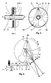
- Figure 2 is a schematic view, in longitudinal section, of a pendulum locking device according to the invention.
- Figure 3 is a front view of the pendulum lock.
- Figure 4 shows schematically the operation of the pendulum and a locking device.
- Figure 5 is a diagram of the power supply of the locking device.
- Figures 6a, 6b, 6c are diagrams illustrating the operation of the electric locking device.
- Figure 7 shows schematically a hydraulic control system of the lock.
- FIG. 1 partially shows, in perspective, an articulated vehicle according to the invention comprising two frames, respectively, a rear frame 1 and a front frame 2, articulated one over the other about a longitudinal axis. x'x, via a hinge 3 comprising a central shaft 21 and a tubular sheath 11 mounted rotatably on one another via unrepresented bearings.
- the tubular sheath 11 is integral with the rear frame 1 and carries, at its rear end, two arms 12a, 12b which rest on a rear axle 13 bearing on the ground by two spaced wheels rotating about a transverse axis orthogonal to the longitudinal axis x'x.
- the central shaft 21 is integral with the front frame 2 which rests on a steering wheel 22 mounted on a steering column 23 and oriented by a handlebar or wheel 26.
- the front frame 2 carries at least one seat for the driver and the assembly is enclosed in a protective case not shown in the figure.
- the rear frame 1 is centered on a longitudinal median plane P1 passing through the axis of articulation x'x and orthogonal to the ground while the front frame 2 is centered on a longitudinal median plane P2 which can tilt on one side or the other relative to the first median plane P1 by rotating about the axis of articulation x'x.
- the inclination of the front frame 2 relative to the rear frame 1 can be prevented by a device 6 for locking the hinge 3 controlled by a pendulum member.
- the articulation locking system comprises two parts, secured respectively to the two articulated frames, namely a first part integral in rotation with the rear frame 1 and a second part, fixed in rotation with the front frame. 2.
- the joint can be blocked by solidarisant these two parts.
- the rear frame 1 rests, via a suspension 14, on a rear axle 13 with two wheels spaced a sufficient distance to ensure stability at rest and, however, reduced to not increase the bulk of the vehicle.
- the entire front frame 2, carrying the front steering wheel 22 and at least one seat 24 for the driver, is surrounded by a body forming a closed body, which is not shown in the figure for the sake of clarity.
- the hinge 3 shown in detail in Figure 2, comprises a central shaft 21 secured to the front frame 2 and threaded into a tubular sheath 11 secured to the rear frame 1 and can be blocked by a removable device 6.
- This locking device 6 which is shown in detail in FIGS. 2 and 3, essentially comprises a casing 61 fixed to the tubular sheath 11 of the rear frame 1 and bounded by a cylindrical shell inside which a pendulum is placed. 62 suspended around a longitudinal axis 63 on an arm 64 integral in rotation with the central shaft 21 of the front frame 2 and perpendicular thereto.
- the central shaft 21 passes with play into an opening of the pendulum 62 which can thus oscillate on either side of the median plane P2 of the front frame 2 in which is placed the suspension axis 63 of the pendulum 62.
- This is balanced by a lower flyweight 65 comprising two bosses 66a, 66b spaced from the inner face of the shell of the housing 61 by a very small clearance j.
- FIG. 4 shows the operation of the forces involved when the vehicle body, secured to the front frame 2, tends to incline, for example to the right, the suspension axis 63 of the pendulum carried by the arm 64 integral in rotation of the central shaft 21 tending to rotate about the axis x'x in the direction of the arrow F.
- ⁇ being the coefficient of friction of the boss 66 on the inner surface of the shell 61 of the housing, there is buttressing of the stand formed by the pendulum 62 and, therefore, blocking the rotation, the two parts 11 and 21 being secured in rotation.
- the hinge 3 is blocked, the front frame 2 remaining slightly inclined relative to the ground.
- the driver can bow in the curves, maintaining the median plane P2 of the front frame 2 in the plane of the apparent vertical, that is to say the resultant of gravity and centrifugal force.
- the center of gravity of the pendulum then remains in the median plane P2 of the front frame 2.
- the vehicle behaves en route as a two-wheel vehicle with dynamic stability.
- the front frame 2 therefore tends to incline relative to the ground and its median plane P2 deviates from one side or the other relative to the median plane P1 of the rear frame 1 which remains perpendicular to the ground.
- the vehicle is provided with an auxiliary platform 5 to straighten the body, at the start, to unlock the joint and leave in a straight line.
- the auxiliary platform 5 is fixed, at the rear, on the tubular sheath 11 and comprises two parts forming footrests 52 which extend on either side of the central shaft 21 of the front chassis 2 and rest thereon, at the front, by a bearing 53 on which the shaft 21 rotates if the front chassis is tilted 2.
- the driver can therefore, after closing the body, to bear on one of the footrest 52, the side to which the front frame 2 is inclined, to straighten it to unlock the joint, the center of gravity the flyweight 65 returning to the median plane P 2 of the front frame 2.
- the driver is supported on two footrests 25 integral with the front frame 2.
- the locking system is preferably provided with a pendulum locking device controlled from a speed threshold. Above this speed, which corresponds to that from which the dynamic stability can be ensured, the articulation locking control is locked, the body being perfectly free to tilt and the driving of the vehicle being identical to that a two-wheeled vehicle.
- Such a locking device 7 shown schematically in FIG. 4 comprises, for example, a latch 71 mounted at the end of an arm 72 rotating around an axis 70 and engageable in a notch 67 in the plane median of the 65 weight.
- a return spring 73 acting on the arm 72 holds the latch 71 in a remote position allowing the operation of the pendulum and the locking of the articulation, if necessary.
- an electromagnet 74 actuated by a control device 8 comprising a speed measuring means makes it possible, starting from a certain speed threshold, to engage the latch 71 in the notch 67 and, consequently, to block the pendulum 62 in its equilibrium position releasing the joint. Below this speed threshold, the electromagnet 74 does not work and the latch 71, recalled by the spring 73, releases the pendulum 62.
- FIG. 5 gives, by way of example, a diagram of an electrical system for controlling the lock 71.
- the speed measuring device comprises a wheel 75 called “sound wheel” associated, for example, with one of the wheels of the vehicle or any pinion whose speed of rotation is proportional to the speed of the vehicle.
- This wheel 75 carries a raised metal mark 76 whose passage near a sensor 77 provides a pulse in a circuit U for receiving a timed relay 8 comprising, according to the usual names, functions B or C.
- this timed relay 8 comprises a circuit U which receives the pulses of the sensor 77, two series circuits C 1 and C 2 which constitute the control circuit and a load circuit Z which supplies the electromagnet 74 or at least a control relay of this electromagnet.
- the charging circuit Z is not energized as long as the time interval t 1 between two pulses u 1 , u 2 is greater than a delay t and it is supplied with continue as soon as t 1 is smaller than t.
- a pulse U 1 triggers a short closing of the circuit C 1 but only after a delay time t and an immediate closing of the circuit C 2 for a time t 0 slightly less than t.
- the electromagnet 74 is then powered and tilts the lever 72 rotating about the axis 70 which is integral, as the axis 63 of suspension of the pendulum, the plate 64, itself secured in rotation of the front frame 2
- the latch 71 then engages in the notch 67 and the pendulum 62 and locked in its central position can not produce any blockage between the two front frame 2 and rear 1.
- the vehicle then behaves like a two wheels.
- the pendulum 62 is unlocked when t 1 becomes greater than t and the articulation locks to ensure the stability of the vehicle.
- Figure 7 shows schematically, by way of example, another control system for locking and unlocking the pendulum 62.
- the pendulum 62 can be locked in its median position by a latch 71 which may consist, for example, of a roller engaging in a notch 67 of the pendulum 62.
- This latch 71 is mounted at the end a lever 72 pivoting about an axis 70 and held in the spaced position by a return spring 73.
- This pusher 78 is mounted on the piston 81 of a jack 80 having a pressure chamber fed by a suction-booster pump 82 comprising a cylindrical body inside which is slidably mounted. a piston 83 actuated by a voice wheel 75 whose rotational speed is related to the speed of movement of the vehicle.
- the movement back and forth of the piston 83 is controlled for this purpose by a pair of permanent magnets mounted in opposition, that is to say with the poles of the same name face to face, one, 84 on the wheel 75 and the other 85 at the end of a rod connected to the piston 83.
- a spring 86 returns the piston 83 to the rest position.
- the piston 83 thus receives a pulse each time the magnet 84 passes in front of the magnet 85 and sends towards the jack 80, through a non-return valve 86, a certain quantity of fluid which moves the piston 81 of the cylinder 80 from a position V 1 to a position V 2 and, as a result, the roller 71 from a position T 1 to a position T 2 .
- Successive analogous actions tend to make the roller 71 enter the notch 47.
- the jack is provided with a controlled leakage orifice 87 whose damping action combined with the return of the spring 73, places the movement of the roller 71 under the influence of the frequency of movement of the pump 82, that is to say, ultimately, under the influence of the vehicle speed.
- a valve 88 limits the pressure in the circuits and returns the fluid to an unpressurized reservoir 89 as the velocity increases.
Landscapes
- Engineering & Computer Science (AREA)
- Mechanical Engineering (AREA)
- Vehicle Body Suspensions (AREA)
- Automatic Cycles, And Cycles In General (AREA)
- Body Structure For Vehicles (AREA)
- Polarising Elements (AREA)
- Braking Arrangements (AREA)
- Mechanical Operated Clutches (AREA)
- Motorcycle And Bicycle Frame (AREA)
- Handcart (AREA)
Applications Claiming Priority (2)
| Application Number | Priority Date | Filing Date | Title |
|---|---|---|---|
| FR0107405A FR2825672B1 (fr) | 2001-06-06 | 2001-06-06 | Vehicule articule |
| EP02743351A EP1399357B1 (de) | 2001-06-06 | 2002-06-06 | Gelenkfahrzeug |
Related Parent Applications (2)
| Application Number | Title | Priority Date | Filing Date |
|---|---|---|---|
| EP02743351.5 Division | 2002-06-06 | ||
| EP02743351A Division EP1399357B1 (de) | 2001-06-06 | 2002-06-06 | Gelenkfahrzeug |
Publications (2)
| Publication Number | Publication Date |
|---|---|
| EP1686053A2 true EP1686053A2 (de) | 2006-08-02 |
| EP1686053A3 EP1686053A3 (de) | 2011-08-31 |
Family
ID=8864022
Family Applications (2)
| Application Number | Title | Priority Date | Filing Date |
|---|---|---|---|
| EP06009662A Withdrawn EP1686053A3 (de) | 2001-06-06 | 2002-06-06 | Mit Gelenksperrmechanismus versehene Vorrichtung |
| EP02743351A Expired - Lifetime EP1399357B1 (de) | 2001-06-06 | 2002-06-06 | Gelenkfahrzeug |
Family Applications After (1)
| Application Number | Title | Priority Date | Filing Date |
|---|---|---|---|
| EP02743351A Expired - Lifetime EP1399357B1 (de) | 2001-06-06 | 2002-06-06 | Gelenkfahrzeug |
Country Status (9)
| Country | Link |
|---|---|
| US (2) | US7100727B2 (de) |
| EP (2) | EP1686053A3 (de) |
| JP (1) | JP4129746B2 (de) |
| AT (1) | ATE335646T1 (de) |
| CA (1) | CA2449859C (de) |
| DE (1) | DE60213801T2 (de) |
| ES (1) | ES2271281T3 (de) |
| FR (1) | FR2825672B1 (de) |
| WO (1) | WO2002098722A1 (de) |
Cited By (1)
| Publication number | Priority date | Publication date | Assignee | Title |
|---|---|---|---|---|
| ITBO20110252A1 (it) * | 2011-05-06 | 2012-11-07 | Tartajet S R L | Sospensione ammortizzata ed a ruote indipendenti, per veicoli a motore a tre o più ruote. |
Families Citing this family (21)
| Publication number | Priority date | Publication date | Assignee | Title |
|---|---|---|---|---|
| FR2825672B1 (fr) * | 2001-06-06 | 2003-10-03 | 2P | Vehicule articule |
| NL1021195C2 (nl) * | 2002-07-31 | 2004-02-03 | Brinks Westmaas Bv | Kantelvoertuig. |
| FR2841209B1 (fr) * | 2003-07-07 | 2006-04-28 | 2P | Dispositif de solidarisation entre deux parties d'une articulation, en particulier pour un vehicule. |
| DE112006002581T5 (de) | 2005-09-30 | 2008-09-04 | Harley-Davidson Motor Company Group, Inc., Milwaukee | Neigungsaufhängungsmechanik |
| US7571787B2 (en) | 2005-09-30 | 2009-08-11 | Harley-Davidson Motor Company Group, LLC | Headlight mounting arrangement |
| US20090255747A1 (en) * | 2008-04-10 | 2009-10-15 | Ridevehicles Llc | 3-Wheeled stand-up personal mobility vehicle and components therein |
| JP5237783B2 (ja) * | 2008-12-19 | 2013-07-17 | ヤマハ発動機株式会社 | 鞍乗型車両 |
| US20100320023A1 (en) * | 2009-06-23 | 2010-12-23 | Michael Rhodig | Four wheel vehicle having a rotatable body section and method therefor |
| JP2011046296A (ja) * | 2009-08-27 | 2011-03-10 | Equos Research Co Ltd | 三輪車両 |
| FR2961783B1 (fr) | 2010-06-23 | 2012-08-03 | Veleance | Dispositif de controle de l'inclinaison d'un cadre monte sur un train de roulement inclinable |
| US9926719B2 (en) | 2013-02-13 | 2018-03-27 | Nabors Drilling Technologies Usa, Inc. | Slingshot side saddle substructure |
| US9810027B2 (en) | 2013-02-13 | 2017-11-07 | Nabors Drilling Usa, Lp | Side saddle substructure |
| US9428236B2 (en) * | 2013-11-06 | 2016-08-30 | Bryan Goss | Lean-compensating motorcycle with channel wheels |
| CN105015668B (zh) * | 2015-07-08 | 2018-03-06 | 上海大学 | 一种基于滑块摇杆机构的龙行车式机器人 |
| US10800476B1 (en) | 2017-12-17 | 2020-10-13 | John Suratana Thienphrapa | Motorized cycle |
| CN108528610A (zh) * | 2018-05-29 | 2018-09-14 | 项炳海 | 一种基于宽车轮摩擦制动的自行车 |
| CN109720437A (zh) * | 2019-01-29 | 2019-05-07 | 浙江瑞华康源科技有限公司 | 一种驱动底盘 |
| CN111976868B (zh) * | 2020-09-02 | 2021-07-20 | 台州春来机电有限公司 | 一种高性能的电动三轮车 |
| JP7420699B2 (ja) * | 2020-11-24 | 2024-01-23 | 本田技研工業株式会社 | 車両 |
| IT202000031109A1 (it) * | 2020-12-16 | 2022-06-16 | Piaggio & C Spa | Un motoveicolo con avantreno rollante e carrello posteriore con due ruote motrici |
| US11383792B1 (en) | 2021-08-27 | 2022-07-12 | John Suratana Thienphrapa | Motorized cycle |
Citations (6)
| Publication number | Priority date | Publication date | Assignee | Title |
|---|---|---|---|---|
| GB1561253A (en) | 1977-03-02 | 1980-02-13 | Trautwein W | Threewheeled vehicle |
| US4223795A (en) | 1979-04-09 | 1980-09-23 | Akers Edward G | Child-resistant package |
| DE3611417A1 (de) | 1986-04-05 | 1987-10-22 | Adolf Dipl Ing Fichtner | Roller mit 2 gegenlaeufig schwingenden hinterraedern |
| FR2600612A1 (fr) | 1986-06-27 | 1987-12-31 | Patin Pierre | Procede et dispositifs de stabilisation pour vehicule inclinable |
| FR2639016A1 (fr) | 1988-11-15 | 1990-05-18 | Patin Pierre | Dispositif de stabilisation pour vehicule inclinable |
| FR2688465A1 (fr) | 1992-03-10 | 1993-09-17 | Patin Pierre | Dispositif de stabilisation pour vehicule. |
Family Cites Families (12)
| Publication number | Priority date | Publication date | Assignee | Title |
|---|---|---|---|---|
| US1617357A (en) * | 1925-09-25 | 1927-02-15 | Lowell E Walter | Scooter vehicle |
| US1690342A (en) * | 1927-12-12 | 1928-11-06 | Gustav N Madsen | Velocipede |
| FR1562248A (de) * | 1968-02-22 | 1969-04-04 | ||
| US3572456A (en) * | 1969-01-09 | 1971-03-30 | Arthur D Healy | Bankable tricycle type vehicle |
| FR2154972A5 (de) * | 1971-10-01 | 1973-05-18 | Patin Pierre | |
| US4423795A (en) * | 1982-02-19 | 1984-01-03 | General Motors Corporation | Wheeled vehicle with cambering front module |
| EP1090832A1 (de) * | 1998-05-28 | 2001-04-11 | Avantec Corporation | Dreirad |
| US6453560B1 (en) * | 2000-04-04 | 2002-09-24 | Wenco Llc | Multi-blade cutting device |
| US6315313B1 (en) * | 2000-05-15 | 2001-11-13 | C. Y. Huang | Energy storing bicycle |
| US6543560B1 (en) * | 2000-07-18 | 2003-04-08 | Delta Systems, Inc. | Hydrostatic transmission with integral actuator |
| US6334838B1 (en) * | 2000-11-03 | 2002-01-01 | James Lee | Exercising cart structure |
| FR2825672B1 (fr) * | 2001-06-06 | 2003-10-03 | 2P | Vehicule articule |
-
2001
- 2001-06-06 FR FR0107405A patent/FR2825672B1/fr not_active Expired - Fee Related
-
2002
- 2002-06-06 ES ES02743351T patent/ES2271281T3/es not_active Expired - Lifetime
- 2002-06-06 US US10/479,986 patent/US7100727B2/en not_active Expired - Fee Related
- 2002-06-06 JP JP2003501731A patent/JP4129746B2/ja not_active Expired - Fee Related
- 2002-06-06 AT AT02743351T patent/ATE335646T1/de active
- 2002-06-06 EP EP06009662A patent/EP1686053A3/de not_active Withdrawn
- 2002-06-06 WO PCT/FR2002/001940 patent/WO2002098722A1/fr not_active Ceased
- 2002-06-06 EP EP02743351A patent/EP1399357B1/de not_active Expired - Lifetime
- 2002-06-06 DE DE60213801T patent/DE60213801T2/de not_active Expired - Lifetime
- 2002-06-06 CA CA002449859A patent/CA2449859C/fr not_active Expired - Fee Related
-
2006
- 2006-07-12 US US11/484,617 patent/US7308963B2/en not_active Expired - Fee Related
Patent Citations (6)
| Publication number | Priority date | Publication date | Assignee | Title |
|---|---|---|---|---|
| GB1561253A (en) | 1977-03-02 | 1980-02-13 | Trautwein W | Threewheeled vehicle |
| US4223795A (en) | 1979-04-09 | 1980-09-23 | Akers Edward G | Child-resistant package |
| DE3611417A1 (de) | 1986-04-05 | 1987-10-22 | Adolf Dipl Ing Fichtner | Roller mit 2 gegenlaeufig schwingenden hinterraedern |
| FR2600612A1 (fr) | 1986-06-27 | 1987-12-31 | Patin Pierre | Procede et dispositifs de stabilisation pour vehicule inclinable |
| FR2639016A1 (fr) | 1988-11-15 | 1990-05-18 | Patin Pierre | Dispositif de stabilisation pour vehicule inclinable |
| FR2688465A1 (fr) | 1992-03-10 | 1993-09-17 | Patin Pierre | Dispositif de stabilisation pour vehicule. |
Cited By (1)
| Publication number | Priority date | Publication date | Assignee | Title |
|---|---|---|---|---|
| ITBO20110252A1 (it) * | 2011-05-06 | 2012-11-07 | Tartajet S R L | Sospensione ammortizzata ed a ruote indipendenti, per veicoli a motore a tre o più ruote. |
Also Published As
| Publication number | Publication date |
|---|---|
| CA2449859A1 (fr) | 2002-12-12 |
| JP2004528224A (ja) | 2004-09-16 |
| ATE335646T1 (de) | 2006-09-15 |
| US7308963B2 (en) | 2007-12-18 |
| DE60213801T2 (de) | 2007-03-29 |
| EP1686053A3 (de) | 2011-08-31 |
| US20060249921A1 (en) | 2006-11-09 |
| US7100727B2 (en) | 2006-09-05 |
| FR2825672A1 (fr) | 2002-12-13 |
| US20040173981A1 (en) | 2004-09-09 |
| EP1399357A1 (de) | 2004-03-24 |
| FR2825672B1 (fr) | 2003-10-03 |
| WO2002098722A1 (fr) | 2002-12-12 |
| JP4129746B2 (ja) | 2008-08-06 |
| CA2449859C (fr) | 2010-03-09 |
| DE60213801D1 (de) | 2006-09-21 |
| EP1399357B1 (de) | 2006-08-09 |
| ES2271281T3 (es) | 2007-04-16 |
Similar Documents
| Publication | Publication Date | Title |
|---|---|---|
| EP1399357B1 (de) | Gelenkfahrzeug | |
| EP3041699B1 (de) | Dreirädriges neigefahrzeug | |
| EP0369863B1 (de) | Stabilisierungsvorrichtung für schrägstellbares Fahrzeug | |
| EP0099819B1 (de) | Selbstbetriebenes Fahrzeug mit artikulierbarem Arm, einem Behälter und einer anschaltbaren Betriebsanordnung die durch das Fahrzeug getragen wird | |
| WO2011121211A1 (fr) | Tricycle | |
| EP2542459A1 (de) | Elektrisches fahrzeug mit mindestens drei rädern | |
| WO2001053145A1 (fr) | Vehicule pour terrain accidente | |
| FR2756777A1 (fr) | Mecanisme de transfert a billes comportant un dispositif de freinage, et vehicule utilisant un tel mecanisme | |
| FR2995255A1 (fr) | Systeme de liaison au sol pour vehicule inclinable, tel qu'un tricycle | |
| FR2635729A1 (fr) | Dispositif de correction d'assiette d'un vehicule automobile | |
| EP1240072A1 (de) | Stabilisierungsmittel für zweirad-fahrzeug | |
| FR2815584A1 (fr) | Siege de vehicule avec un support lateral et une boucle de ceinture | |
| WO1979000686A1 (fr) | Dispositif de commande et de controle de l'inclinaison de la caisse d'un vehicule | |
| FR2459154A1 (fr) | Dispositif a inertie pour corriger exactement l'orientation d'un projecteur de vehicule automobile en compensant l'effet des deplacements dynamiques de la partie suspendue par rapport a la partie non suspendue du vehicule. | |
| EP4175728B1 (de) | Passagierrückhaltesystem für achterbahnen | |
| FR2642392A1 (fr) | Vehicule motorise ou tracte | |
| FR2765841A1 (fr) | Dispositif formant appui-tete de siege de vehicule automobile | |
| FR3119766A3 (fr) | Dispositif adaptable pour fauteuil roulant et installation le comportant | |
| FR2841209A1 (fr) | Dispositif de solidarisation entre deux parties d'une articulation, en particulier pour un vehicule. | |
| EP1276449A1 (de) | Motorbetriebene vorrichtung für rollstuhl | |
| FR2838098A1 (fr) | Dispositif stabilisateur escamotable pour vehicule a deux roues, notamment un motocycle | |
| FR2680348A1 (fr) | Perfectionnement a la suspension d'un vehicule inclinable a trois roues. | |
| FR2795652A1 (fr) | Chariot pliable pour sac de golf, possedant des moyens de verrouillage perfectionnes | |
| EP4717576A1 (de) | Dreiradfahrzeug mit automatischem feststellbremssystem | |
| FR3162002A1 (fr) | Dispositif de motorisation pour fauteuil roulant |
Legal Events
| Date | Code | Title | Description |
|---|---|---|---|
| PUAI | Public reference made under article 153(3) epc to a published international application that has entered the european phase |
Free format text: ORIGINAL CODE: 0009012 |
|
| AC | Divisional application: reference to earlier application |
Ref document number: 1399357 Country of ref document: EP Kind code of ref document: P |
|
| AK | Designated contracting states |
Kind code of ref document: A2 Designated state(s): AT BE CH CY DE DK ES FI FR GB GR IE IT LI LU MC NL PT SE TR |
|
| PUAL | Search report despatched |
Free format text: ORIGINAL CODE: 0009013 |
|
| RIC1 | Information provided on ipc code assigned before grant |
Ipc: B62K 5/04 20060101AFI20110718BHEP |
|
| AK | Designated contracting states |
Kind code of ref document: A3 Designated state(s): AT BE CH CY DE DK ES FI FR GB GR IE IT LI LU MC NL PT SE TR |
|
| RIC1 | Information provided on ipc code assigned before grant |
Ipc: B62K 5/04 20060101AFI20110728BHEP |
|
| 17P | Request for examination filed |
Effective date: 20120229 |
|
| AKX | Designation fees paid |
Designated state(s): AT BE CH CY DE DK ES FI FR GB GR IE IT LI LU MC NL PT SE TR |
|
| RIC1 | Information provided on ipc code assigned before grant |
Ipc: B62K 5/02 20060101AFI20120727BHEP |
|
| GRAP | Despatch of communication of intention to grant a patent |
Free format text: ORIGINAL CODE: EPIDOSNIGR1 |
|
| STAA | Information on the status of an ep patent application or granted ep patent |
Free format text: STATUS: THE APPLICATION IS DEEMED TO BE WITHDRAWN |
|
| 18D | Application deemed to be withdrawn |
Effective date: 20130131 |