EP1686224A2 - Dispositif d'ouverture et de fermeture d'accès - Google Patents
Dispositif d'ouverture et de fermeture d'accès Download PDFInfo
- Publication number
- EP1686224A2 EP1686224A2 EP05077535A EP05077535A EP1686224A2 EP 1686224 A2 EP1686224 A2 EP 1686224A2 EP 05077535 A EP05077535 A EP 05077535A EP 05077535 A EP05077535 A EP 05077535A EP 1686224 A2 EP1686224 A2 EP 1686224A2
- Authority
- EP
- European Patent Office
- Prior art keywords
- guide
- folding door
- supplementary
- selector
- door
- Prior art date
- Legal status (The legal status is an assumption and is not a legal conclusion. Google has not performed a legal analysis and makes no representation as to the accuracy of the status listed.)
- Withdrawn
Links
Images

Classifications
-
- E—FIXED CONSTRUCTIONS
- E06—DOORS, WINDOWS, SHUTTERS, OR ROLLER BLINDS IN GENERAL; LADDERS
- E06B—FIXED OR MOVABLE CLOSURES FOR OPENINGS IN BUILDINGS, VEHICLES, FENCES OR LIKE ENCLOSURES IN GENERAL, e.g. DOORS, WINDOWS, BLINDS, GATES
- E06B9/00—Screening or protective devices for wall or similar openings, with or without operating or securing mechanisms; Closures of similar construction
- E06B9/02—Shutters, movable grilles, or other safety closing devices, e.g. against burglary
- E06B9/06—Shutters, movable grilles, or other safety closing devices, e.g. against burglary collapsible or foldable, e.g. of the bellows or lazy-tongs type
- E06B9/0607—Shutters, movable grilles, or other safety closing devices, e.g. against burglary collapsible or foldable, e.g. of the bellows or lazy-tongs type comprising a plurality of similar rigid closing elements movable to a storage position
- E06B9/0646—Shutters, movable grilles, or other safety closing devices, e.g. against burglary collapsible or foldable, e.g. of the bellows or lazy-tongs type comprising a plurality of similar rigid closing elements movable to a storage position characterised by the relative arrangement of the closing elements in the stored position
- E06B9/0669—Shutters, movable grilles, or other safety closing devices, e.g. against burglary collapsible or foldable, e.g. of the bellows or lazy-tongs type comprising a plurality of similar rigid closing elements movable to a storage position characterised by the relative arrangement of the closing elements in the stored position stored in a zig-zag arrangement
-
- E—FIXED CONSTRUCTIONS
- E05—LOCKS; KEYS; WINDOW OR DOOR FITTINGS; SAFES
- E05D—HINGES OR SUSPENSION DEVICES FOR DOORS, WINDOWS OR WINGS
- E05D15/00—Suspension arrangements for wings
- E05D15/26—Suspension arrangements for wings for folding wings
- E05D15/262—Suspension arrangements for wings for folding wings folding vertically
-
- E—FIXED CONSTRUCTIONS
- E06—DOORS, WINDOWS, SHUTTERS, OR ROLLER BLINDS IN GENERAL; LADDERS
- E06B—FIXED OR MOVABLE CLOSURES FOR OPENINGS IN BUILDINGS, VEHICLES, FENCES OR LIKE ENCLOSURES IN GENERAL, e.g. DOORS, WINDOWS, BLINDS, GATES
- E06B3/00—Window sashes, door leaves, or like elements for closing wall or like openings; Layout of fixed or moving closures, e.g. windows in wall or like openings; Features of rigidly-mounted outer frames relating to the mounting of wing frames
- E06B3/92—Doors or windows extensible when set in position
- E06B3/925—Doors or windows extensible when set in position with several wings opening vertically towards the same side of the opening and each closing a separate part of the opening
- E06B3/927—Doors or windows extensible when set in position with several wings opening vertically towards the same side of the opening and each closing a separate part of the opening positioned in one plane when closed
-
- E—FIXED CONSTRUCTIONS
- E06—DOORS, WINDOWS, SHUTTERS, OR ROLLER BLINDS IN GENERAL; LADDERS
- E06B—FIXED OR MOVABLE CLOSURES FOR OPENINGS IN BUILDINGS, VEHICLES, FENCES OR LIKE ENCLOSURES IN GENERAL, e.g. DOORS, WINDOWS, BLINDS, GATES
- E06B9/00—Screening or protective devices for wall or similar openings, with or without operating or securing mechanisms; Closures of similar construction
- E06B9/02—Shutters, movable grilles, or other safety closing devices, e.g. against burglary
- E06B9/06—Shutters, movable grilles, or other safety closing devices, e.g. against burglary collapsible or foldable, e.g. of the bellows or lazy-tongs type
- E06B9/0607—Shutters, movable grilles, or other safety closing devices, e.g. against burglary collapsible or foldable, e.g. of the bellows or lazy-tongs type comprising a plurality of similar rigid closing elements movable to a storage position
- E06B9/0615—Shutters, movable grilles, or other safety closing devices, e.g. against burglary collapsible or foldable, e.g. of the bellows or lazy-tongs type comprising a plurality of similar rigid closing elements movable to a storage position characterised by the closing elements
- E06B9/0638—Slats or panels
-
- E—FIXED CONSTRUCTIONS
- E05—LOCKS; KEYS; WINDOW OR DOOR FITTINGS; SAFES
- E05Y—INDEXING SCHEME ASSOCIATED WITH SUBCLASSES E05D AND E05F, RELATING TO CONSTRUCTION ELEMENTS, ELECTRIC CONTROL, POWER SUPPLY, POWER SIGNAL OR TRANSMISSION, USER INTERFACES, MOUNTING OR COUPLING, DETAILS, ACCESSORIES, AUXILIARY OPERATIONS NOT OTHERWISE PROVIDED FOR, APPLICATION THEREOF
- E05Y2900/00—Application of doors, windows, wings or fittings thereof
- E05Y2900/10—Application of doors, windows, wings or fittings thereof for buildings or parts thereof
- E05Y2900/13—Type of wing
- E05Y2900/132—Doors
Definitions
- the prior art includes devices for opening and closing accesses which comprise a folding door which can be folded into a packed conformation, being constituted of a plurality of slats all hinged one to another.
- folding doors are slidingly mobile along a perpendicular direction to the hinge lines along two guides, in which sliding elements solidly constrained to the door are slidable.
- the sliding guides are solidly constrained to the perimeter of the access at the sides of the access, and have the function of guiding the sliding motion of the door.
- a device of the above type is described in a patent application filed by the same applicant, in which device the sliding direction of the folding door is vertical.
- the device comprises a motor for sliding the door, which motor is connected to the folding door at a bottom slat thereof or preferably a bottom edge of the bottom slat.
- the upper edge of the door can be hinged to the guides or can be slidable and rotatably within the guides.
- the lifting of the bottom slat of the door causes the slats to fold immediately, while in the second case the door has a short sliding run at the end of which the upper edge of the door strikes against an endrun stop and the doorslats begin to fold up.
- Known-type devices exhibit some drawbacks. Firstly the door folding involves all of the slats equally, i.e. the door folds contemporaneously along all the fold lines between the slats. This leads to the need to guarantee a free space around the door, the extension of which free space depends on the size of the slats. Objects cannot be placed in proximity of the door and it is obviously not possible to park vehicles, for example, in the close vicinity. This makes prior art folding doors unsuitable for closing garages, as very often vehicles are parked extremely close thereto.
- a main aim of the present invention is to provide a device for opening and closing accesses which obviates the drawbacks in prior-art devices.
- An advantage of the proposed device is that it requires a very small space in which to be activated.
- a further advantage of the device is that it is provided with effective means for supporting the folded and raised door, which is perfectly suited to manual operation.
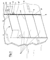
- the device comprises a folding door 2, which is foldable into a pack of at least two slats 3 along a hinge line 4.
- the folding door 2 can be sub-divided into a greater number of slats 3 according to the size of the access to be closed.
- the number of slats 3 the door is subdivided into is an equal number, so that in a folded configuration all the slats 3 can be superposed in a pack.
- the folding door 2 is slidingly mobile along a perpendicular direction to the hinge line or lines 4.
- the folding door is slidable along a vertical direction and folds into a pack above the door access.
- the door is slidingly mobile between a closed position, in which it assumes a flat configuration and closes the access at which it is arranged, and an open position, in which it is folded up and frees the access.
- the raising movement of the door can be performed by a motor of known type and not represented in the figures of the drawings, which motor is associated to the bottom slat of the folding door.
- Two guides 5, in which sliding elements 6, 6' are inserted, which sliding elements 6, 6' are solidly constrained to the door, are arranged at the sides of the door 2 to guide the sliding movement thereof.
- the guides 5 and the sliding elements 6, 6' are commonly used in the realisation of sliding doors.
- Each guide 5 is typically defined by a race delimited by a bottom wall and two parallel lateral walls.
- the sliding elements 6, 6' are constituted by little wheels, associated to the sides of the door, which roll on one of the two parallel walls delimiting the guide 5. In the folded configuration, part of the sliding elements 6 are internal of the guide 5, while the remaining part of the sliding elements 6' are external of the guide 5.
- the folding of the door occurs at an intermediate section of the lateral guides 5. On one side of the section the door is in a folded configuration, while on the opposite side of the section the door is in a flat configuration. Considering an intermediate position between the closed position and the open position, the portion of the door 2 which is one side of the intermediate section of the guides 5 is in the folded configuration, while the remaining portion of the door 2 is in the flat configuration.
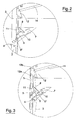
- Each of the guides 5 comprises at least a lateral spur 7 which is coplanar to the guide 5 and inclined with respect thereto.
- the spur 7 is constituted by a race which is similar to the one defining the guide 5.
- a lateral wall of the spur 7 is joined to a lateral wall of the guide 5, with no break in the continuity.
- the spur 7 can also be defined simply by an interruption on a lateral wall of the guide 5.
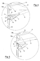
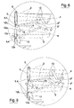
- At least a selector 8 is mobile between at least a first position (figures 2, 3, 5) at which it interrupts the guide 5 and places a tract of the guide 5 in contact with the lateral spur 7, and at least a second position (figure 4) in which it does not interrupt the guide 5 and separates the guide 5 from the lateral spur 7.
- the selector 8 is mobile between its first and second positions in a rotating motion.
- the first and second positions of the selector 8 are extreme end-run positions, in the sense that the selector 8 cannot rotate beyond those two positions.
- the selector 8 is provided with a directional surface 9 which, in the first position, is arranged transversally with respect to the guide 5 and connects the guide 5 to the lateral spur 7, while in the second position it is arranged on a side of the guide 5 and separates the guide 5 from the spur 7.
- the directional surface 9 constitutes an external lateral wall of the spur 7 which stretches as far as the internal part of the guide 5.
- the sliding element is an external sliding element 6'.
- the selector 8 is in the second position thereof (figure 4)
- the directional surface 9 defines a lateral wall of the guide 5, so that a sliding element 6, 6' running along the guide 5 is not deviated into the spur 7 (in this case the sliding element is an internal sliding element 6).
- the selector 8 further comprises a first activating surface 10.
- the first activating surface 10, in the selector 8 first position is arranged transversally of the lateral spur 7.
- a sliding element 6, 6' which, running along the guide 5 in the raising direction of the folding door 2, meets the direction surface 9, is deviated along the lateral spur 7.
- the sliding element 6' enters into contact with the first activating surface 10 (figure 3) and rotates the selector 8 from the first to the second position.
- the selector 8 is free to rotate between the first and second position without overrunning either position.
- the first activating surface 10 is external of the lateral spur 7.
- the selector 8 further comprises a second activating surface 11 which, in the second position of the selector 8 (figure 4) is arranged transversally of the guide 5.
- a sliding element 6 is not deviated along the lateral spur 7, but runs along the guide 5.
- the sliding element 6 enters into contact with the second activating surface 11 and rotates the selector 8, from the second to the first position.
- the second activating surface 11 is external of the guide 5.
- the sliding elements 6 are also arranged at the ends of the upper edge and the bottom edge of the door 2. Internal sliding elements 6 are also arranged at the ends of the intermediate hinge line 4, while the external sliding elements 6' are arranged at the sides of the folding door 2 in proximity of the remaining hinge lines 4. Each sliding element 6 associated to the upper edge of the folding door 2 is predisposed to enter into contact with and endrun stop arranged at an upper end of the guide 5. The endrun stop is arranged in a position in which when the sliding elements 6 associated to the upper edge of the folding door 2 enter into contact therewith, the sliding elements 6' (external) associated to the upper hinge line 4 (i.e. the hinge line arranged at the bottom edge of the upper slat 3 of the folding door 2) are at the initial part of the lateral spur 7.
- the functioning of the device is simple and effective. Taking the closed configuration of the door 2 as the start configuration, and the sliding direction of the door 2 as being therefore from the closed position into the open position, at least the sliding elements 6, arranged at the ends of the upper edge of the folding door 2, are in a downstream position with respect to the selector 8 of the respective guides. The remaining sliding elements 6, 6' are arranged upstream of the selector 8 of each guide 5. In this initial configuration the selector 8 is in the first position thereof. When raising the door 3 into the open position, it remains in a flat configuration up until the moment in which the sliding elements 6 associated to the upper edge strike the endrun stops of the guides 5.
- This operating cycle is repeated until the sliding elements 6' associated to the bottom edge of the folding door 3 (see figure 4) find the electors 8 in the second position thereof and proceed along the guides 5 up until the folding doors is completely packed, after having rotated the selectors 8 into the first position thereof. From this folded position, the folding door 2 can return into its closed configuration by inverting all of the above-described stages.
- the geometry of the device is such that in order to reach the closed position the folding door 2 need only slide in an opposite direction to that which brought it into the folded position.
- An important advantage of the device of the present invention is that during the raising of the folding door 2, the part of the door 2 below the selector 8 stays in the flat configuration. This means that the space adjacent to the folding door 2 below the selector 8 is in no way affected by the folding movement of the door 2 and does not perforce have to be left free, but can be used in some way: in the case, for example, of the device's being used for the closing of a garage, a vehicle can be brought right up to the door without any risk of interference or contact during the opening and closing of the door itself.
- the device of the invention comprises means for supporting predisposed to support the folding door 2 in its folded configuration.
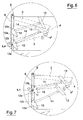
- the means for support (figure 6-9) comprise at least a first con rod 12, oscillating about an axis between an operative position, in which it interferes with the guide 5 at least partially in a transversal direction, and a non-operative position, in which it is external of the guide 5.
- the means for supporting further comprise at least a second con rod 13, which oscillates between two extreme positions about an axis, and a rod 14, hinged at ends thereof to the first and second con rods 12, 13.
- the rod 14 is hinged to the first and the second con rods 12, 13 at intermediate portions of the two con rods 12, 13 located between the oscillating axis and the free ends of the con rods 12, 13.
- the oscillation axes of the con rods 12, 13 are preferably horizontal and parallel to the hinge lines of the folding door 2.
- Elastic means or other means, not illustrated, are predisposed to exert an action which pushes the first con rod 12 into the inter
- the first con rod 12 exhibits a first engaging surface 12a and a second engaging surface 12b.
- first engaging surface 12a forms an acute angle with respect to the door 2 raising direction
- second engaging surface 12b forms an acute angle with respect to the door 2 lowering direction.
- the first con rod 12 is positioned in such a way as to be rotated by the internal sliding elements 6 (those running along the guide 5 without exiting it).
- an internal sliding element 6 meets the first engaging surface 12a (figures 6, 7, 8) it rotates the first con rod 12 towards the non-operative position.
- the rotation of the first con rod 12 into the non-operative position induces a corresponding rotation of the second con rod 13 by means of the rod 14.
- the rotation of the second con rod 13 (figures 6, 8) enables passage of the external sliding element 6' which precedes the internal sliding element 6 which has interacted with the first con rod 12; the second con rod 13 is positioned so that when the first con rod 12 is in the operative position, the second con rod 13 intersects the arced trajectory described by the external sliding elements 6' during the folding of the folding door 2.
- the second con rod 13 does not intersect the arced trajectory.
- the first con rod 12 returns into the operative position, and correspondingly the second con rod 13 returns into a position in which it intersects the arced trajectory described by the external sliding elements 6'.
- the second con rod 13 is positioned and of such a size as to be arranged below the external sliding element 6' (figure 9). In this position the weight of the folding door 2, which falls on the second con rod 13 by means of the external sliding element 6', forces the first con rod 12 into the operative position thereof, in which it prevents a descent, by force of gravity, of the internal sliding elements 6.
- each guide 5 there is a first group consisting of: a first con rod 12, a second con rod 13, a rod 14; and a second group of: a first con rod 12, a second con rod 13, a rod 14; the second group being located in a superior position to the first group.
- the upper group i.e. the second group, supports the two upper portions of the folding door 2, while the lower group, i.e. the first group, supports the two lower portions of the folding door 2.
- the means for supporting are especially useful if the door 2 is predisposed for manual activation, as in the case of a domestic use, for closing a garage, for example. If the activating is governed by a motor having a braking system, the means for supporting can be unnecessary and omitted from the realisation of the invention.
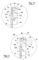
- the means for supporting comprise at least two supplementary first guides 20 which are coplanar and located by a side of at least a tract of each guide 5 and are arranged on the internal side of the folding door 2, i.e. on the side of the door 2 where the slats 3 are arranged in folded position.
- Each of the supplementary guides comprises at least a first tract 21, parallel to the guide 5, at least an intermediate tract 22 which progressively diverges from the guide 5, at least a terminal tract 23 arranged transversally with respect to the guide 5.
- Each supplementary guide 20 is constituted by an element, projecting from a sheet 24, which element is shaped in such a way as to define a wall which can function as a sliding track in which the intermediate tract 22 develops, in a curved direction. At one end the intermediate tract 22 connects to the first tract 21, extending therefrom in a curving direction, distancing from the guide 5, up until it is parallel to the guide 5.
- the means for supporting also comprise two second supplementary guides 20a, belonging to the first supplementary guides 20, which are positioned upstream with respect to the raising direction of the door 2.
- the first tract 21 of the first guide 20 is connected to a terminal tract 23a of the second guide 20a.
- the first supplementary guides 20 are arranged in an upper position and support the upper slat and the adjacent slat (the second slat from the top), while the second supplementary guides 20a are arranged below and are predisposed to support the bottom slat and the next up, i.e. the third slat from the top.
- the top slat is denoted by 3a, the second by 3b, the third by 3c and the bottom slat by 3d.
- the supporting action of the first guides 20 is developed through interaction with at least two pairs of supplementary sliding elements 26, 26' of the top slat 3a, arranged by the sides of the door 2.
- a first element 26 of each pair of the supplementary sliding elements 26 is predisposed to slide externally along one of the guides 5.
- the second element 26' of the same pair is predisposed to slide along a supplementary guide 20 which is coplanar to the above-cited guide 5, following the rotation movement which the top slat 3a performs during the folding of the door 2.
- the supplementary sliding elements 26, 26' of each pair are arranged at a side of the door 2 and, in the flat configuration (i.e. the closed configuration) of the folding door 2 they are aligned in contact with a side of the guide 5.
- the folding of the door 2 is achieved by activating the door 2 to slide upwards.
- the folding thereof i.e. the rotation of the slats 3
- the supplementary sliding elements 26, 26' are arranged in such a position that, when the door 2 begins to fold, i.e.
- the first supplementary sliding element 26 has already gone past the first supplementary guide 20, while the second supplementary element is at the start of the intermediate tract 22 of the first supplementary guide 20 and begins to slide long the intermediate tract 22.
- the second supplementary sliding element 26' continues to slide along the first supplementary guide 26 up until a position is reached in which the top slat 3a is in the final position in which, in the preferred embodiment of the sliding door 2, the top slat 3a is aligned with the first supplementary element 26 along a line which is about horizontal.
- each downwards-directed displacement of the first and second supplements elements 26, 26' is prevented. This is because the intermediate tract 22 of the first supplementary guide 20, when crossed in a downwards direction, converges towards the guide 5. A contemporaneous displacement of the supplementary sliding elements 26, 26' in a downwards direction would cause the second element 26' to converge towards the first element 26. This relative movement is prevented as the supplementary sliding elements 26, 26' are firmly constrained to the same slat of the door 2 and consequently any contemporaneous downwards movement is prevented.
- the only permitted downwards movement the top slat 3a and the second slat 3b can make is one in which the second supplementary element 26' runs along the whole intermediate tract 22, disengages there-from and goes into the first tract 21 of the first supplementary guide 20.
- the first supplementary sliding element 26 does not displace downwards. This means that the door 2 can in no case slide uncontrolledly downwards, but can descend only respecting the sequence of the correct unfolding of the slats 3.
- first supplementary guide 20 and the first and second supplementary sliding elements 26, 26' is identical for the second supplementary guide 20a and a third and fourth supplementary sliding guide 26a, 26'a, solidly constrained to the third slat 3c.
- the third slat 3c of the door 2 exhibits at least two pairs of supplementary sliding elements 26a, 26'a arranged at the sides of the folding door 2.
- a first element 26a of the elements precisely the third from the top considering the elements solidly constrained to the first slat 3a as the first, is predisposed to slide externally along a guide 5.
- the second (the fourth if we consider the remaining supplementary sliding elements) is predisposed to slide along the supplementary guide 20 which is coplanar to the guide 5, following the rotation movement of the third slat 3c of the folding door 2 during the folding of the door 2.
- the sliding elements solidly constrained to the first slat 3a, the supplementary sliding elements 26a, 26'a, solidly constrained to the third slat 3c, are arranged in a position such that when the third slat 3c starts rotating about the internal sliding elements 6 associated thereto, the first supplementary sliding element 26a has already passed by the first supplementary guide 20, while the second supplementary element 26'a is at the start of the intermediate tract 22a of the second supplementary guide 20a.
- the overall operating principle of the supplementary guides 20, 20a can be summarised by considering a non-flat configuration of the folding door 2 (i.e. intermediate between the flat configuration and the folded configuration of the door 2, and comprising the latter) in which the slats (3a, 3b, 3c and 3d) are in an inclined position with respect to a vertical plane and the second 26' and the fourth 26'a supplementary sliding elements are at an intermediate point respectively of the intermediate tract 22 and 22a of the first 20 and the second 20a supplementary guide.
- the second embodiment of the means for supporting the folded door exhibits, with respect to the previous embodiment, the advantage of being very compact and simple, as it does not require the use of parts in movement, but exploits simple geometrical constraints.
Landscapes
- Engineering & Computer Science (AREA)
- Structural Engineering (AREA)
- Civil Engineering (AREA)
- Architecture (AREA)
- Mechanical Engineering (AREA)
- Extensible Doors And Revolving Doors (AREA)
- Vehicle Step Arrangements And Article Storage (AREA)
- Wing Frames And Configurations (AREA)
Applications Claiming Priority (1)
| Application Number | Priority Date | Filing Date | Title |
|---|---|---|---|
| ITMO20050019 ITMO20050019A1 (it) | 2005-01-28 | 2005-01-28 | Dispositivo per l'apertura e la chiusura di varchi di accesso. |
Publications (2)
| Publication Number | Publication Date |
|---|---|
| EP1686224A2 true EP1686224A2 (fr) | 2006-08-02 |
| EP1686224A3 EP1686224A3 (fr) | 2008-02-13 |
Family
ID=36279015
Family Applications (1)
| Application Number | Title | Priority Date | Filing Date |
|---|---|---|---|
| EP05077535A Withdrawn EP1686224A3 (fr) | 2005-01-28 | 2005-11-04 | Dispositif d'ouverture et de fermeture d'accès |
Country Status (2)
| Country | Link |
|---|---|
| EP (1) | EP1686224A3 (fr) |
| IT (1) | ITMO20050019A1 (fr) |
Cited By (3)
| Publication number | Priority date | Publication date | Assignee | Title |
|---|---|---|---|---|
| EP1911918A1 (fr) * | 2006-10-06 | 2008-04-16 | Besenzoni S.p.A. | Porte d'accès, en particulier pour des bateaux |
| EP3176356A3 (fr) * | 2015-12-04 | 2017-07-05 | BUBENDORFF Société Anonyme | Dispositif de fermeture |
| CN113250557A (zh) * | 2021-06-11 | 2021-08-13 | 中国舰船研究设计中心 | 防门板下落安全保护装置 |
Family Cites Families (1)
| Publication number | Priority date | Publication date | Assignee | Title |
|---|---|---|---|---|
| US2020544A (en) * | 1932-06-02 | 1935-11-12 | Mcilwraith | Folding sectional door |
-
2005
- 2005-01-28 IT ITMO20050019 patent/ITMO20050019A1/it unknown
- 2005-11-04 EP EP05077535A patent/EP1686224A3/fr not_active Withdrawn
Cited By (3)
| Publication number | Priority date | Publication date | Assignee | Title |
|---|---|---|---|---|
| EP1911918A1 (fr) * | 2006-10-06 | 2008-04-16 | Besenzoni S.p.A. | Porte d'accès, en particulier pour des bateaux |
| EP3176356A3 (fr) * | 2015-12-04 | 2017-07-05 | BUBENDORFF Société Anonyme | Dispositif de fermeture |
| CN113250557A (zh) * | 2021-06-11 | 2021-08-13 | 中国舰船研究设计中心 | 防门板下落安全保护装置 |
Also Published As
| Publication number | Publication date |
|---|---|
| ITMO20050019A1 (it) | 2006-07-29 |
| EP1686224A3 (fr) | 2008-02-13 |
Similar Documents
| Publication | Publication Date | Title |
|---|---|---|
| US7707687B2 (en) | Opening/closing device for a double flap door of an item of furniture | |
| CN103477012B (zh) | 滑升门 | |
| EP1686224A2 (fr) | Dispositif d'ouverture et de fermeture d'accès | |
| CN110130789B (zh) | 一种平开窗 | |
| CN208815453U (zh) | 一种车库拐角墙壁汽车防撞结构 | |
| CN219034502U (zh) | 一种基于弹性合页开启的折叠门和折叠窗 | |
| JP6496465B2 (ja) | 3面構造を持つフォールディングドアの折り畳み装置 | |
| JPH04108793U (ja) | パネルシヤツターの落下防止装置 | |
| KR100600238B1 (ko) | 머시닝 센터에서의 링크 연결식 슬라이드 도어 장치 | |
| CN106168091B (zh) | 大开度暗铰链 | |
| CN109972355A (zh) | 把手组件、分配器、洗涤剂盒部装及衣物处理设备 | |
| KR101834869B1 (ko) | 폴딩도어 고정구조 | |
| KR20130115918A (ko) | 이중 상부 레일 구조를 갖는 폴딩 도어장치 | |
| KR102870897B1 (ko) | 자동 닫힘 기능을 갖는 슬라이딩 폴딩도어조립체 | |
| KR102191373B1 (ko) | 개스스프링과 움직도르래를 이용한 반자동식 스윙 도어 | |
| CN211598330U (zh) | 一种门体结构及售货机 | |
| KR20110026546A (ko) | 여닫이 문 | |
| CN219412344U (zh) | 一种吊挂式移动折叠门 | |
| EP4729736A1 (fr) | Mécanisme pour l'ouverture de portes pliantes | |
| CN222149368U (zh) | 一种用于隐藏式升降茶几的同步翻转升降架 | |
| JP3648811B2 (ja) | ブラインド装置 | |
| CN212995084U (zh) | 洗头头套张开机构及洗头头套 | |
| KR200421284Y1 (ko) | 빨래 건조장치 | |
| KR200407747Y1 (ko) | 접철식 골프 연습장 | |
| JPH08246765A (ja) | ブラインド装置 |
Legal Events
| Date | Code | Title | Description |
|---|---|---|---|
| PUAI | Public reference made under article 153(3) epc to a published international application that has entered the european phase |
Free format text: ORIGINAL CODE: 0009012 |
|
| AK | Designated contracting states |
Kind code of ref document: A2 Designated state(s): AT BE BG CH CY CZ DE DK EE ES FI FR GB GR HU IE IS IT LI LT LU LV MC NL PL PT RO SE SI SK TR |
|
| AX | Request for extension of the european patent |
Extension state: AL BA HR MK YU |
|
| PUAL | Search report despatched |
Free format text: ORIGINAL CODE: 0009013 |
|
| AK | Designated contracting states |
Kind code of ref document: A3 Designated state(s): AT BE BG CH CY CZ DE DK EE ES FI FR GB GR HU IE IS IT LI LT LU LV MC NL PL PT RO SE SI SK TR |
|
| AX | Request for extension of the european patent |
Extension state: AL BA HR MK YU |
|
| RIC1 | Information provided on ipc code assigned before grant |
Ipc: E06B 3/48 20060101ALI20080109BHEP Ipc: E06B 9/06 20060101ALI20080109BHEP Ipc: E05D 15/26 20060101AFI20060516BHEP |
|
| AKX | Designation fees paid | ||
| REG | Reference to a national code |
Ref country code: DE Ref legal event code: 8566 |
|
| STAA | Information on the status of an ep patent application or granted ep patent |
Free format text: STATUS: THE APPLICATION IS DEEMED TO BE WITHDRAWN |
|
| 18D | Application deemed to be withdrawn |
Effective date: 20080814 |