EP1686231A1 - Vorrichtung zur Verhinderung von Schäden an Behängen - Google Patents
Vorrichtung zur Verhinderung von Schäden an Behängen Download PDFInfo
- Publication number
- EP1686231A1 EP1686231A1 EP05405648A EP05405648A EP1686231A1 EP 1686231 A1 EP1686231 A1 EP 1686231A1 EP 05405648 A EP05405648 A EP 05405648A EP 05405648 A EP05405648 A EP 05405648A EP 1686231 A1 EP1686231 A1 EP 1686231A1
- Authority
- EP
- European Patent Office
- Prior art keywords
- sleeve
- coupling
- elevator
- coupling means
- elevator shaft
- Prior art date
- Legal status (The legal status is an assumption and is not a legal conclusion. Google has not performed a legal analysis and makes no representation as to the accuracy of the status listed.)
- Granted
Links
Images


Classifications
-
- E—FIXED CONSTRUCTIONS
- E06—DOORS, WINDOWS, SHUTTERS, OR ROLLER BLINDS IN GENERAL; LADDERS
- E06B—FIXED OR MOVABLE CLOSURES FOR OPENINGS IN BUILDINGS, VEHICLES, FENCES OR LIKE ENCLOSURES IN GENERAL, e.g. DOORS, WINDOWS, BLINDS, GATES
- E06B9/00—Screening or protective devices for wall or similar openings, with or without operating or securing mechanisms; Closures of similar construction
- E06B9/24—Screens or other constructions affording protection against light, especially against sunshine; Similar screens for privacy or appearance; Slat blinds
- E06B9/26—Lamellar or like blinds, e.g. venetian blinds
- E06B9/28—Lamellar or like blinds, e.g. venetian blinds with horizontal lamellae, e.g. non-liftable
- E06B9/30—Lamellar or like blinds, e.g. venetian blinds with horizontal lamellae, e.g. non-liftable liftable
- E06B9/32—Operating, guiding, or securing devices therefor
- E06B9/322—Details of operating devices, e.g. pulleys, brakes, spring drums, drives
Definitions
- the invention relates to a device for preventing damage to hangings according to the preamble of patent claim 1.
- Hangings such as blinds with non-compressible lateral elevator means such as chains or steel bands, in particular motor-driven shutters or blinds, are exposed to a latent risk of damage from objects or other obstacles which are in the path of the blind or the store. There is also the risk of damage by ice or snow in the lateral guides, which can prevent lowering.
- Devices are known from the prior art, which should protect the blinds from damage.
- a widely known device is the end rail, ie, in principle, the lowest blade, in contact with to decouple an obstacle in the guideway from the lateral elevator means. By decoupling the end rail and the function of the anti-surge can be impaired.
- An object of the present invention is to provide a device for preventing damage to hangings, in which the elevator shaft is decoupled from the elevator wheel when a predetermined resistance is exceeded by the curtain and - after removal of the obstacle - is connected again true to angle.
- the inventive connection between the elevator shaft and the elevator wheel allows uncoupling of the two elements and later a true-angle re-engagement after removal of the obstacle.
- the drive motor can continue to rotate until the duration of a regular closing time without the store being damaged.
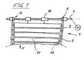
- FIG. 1 only the essential elements of the invention of a slat blind 1 are shown.
- An elevator shaft 3 is driven by a motor M not shown directly or by an unillustrated transmission by hand.
- the elevator means 7 in turn are protected and guided on all sides within guide rails 9 with a C-shaped cross-section.
- a plurality of fins 11 are used, the ends of which are pivotally guided via pivot pins 13 in the guide rails 9.
- connection between the lowermost fin 11 and the elevator means 7 is not part of this invention; It is well known in the prior art and in many variants.
- a turning device 15 can furthermore be arranged on the winding shaft 3, by means of which the blade angle can be adjusted.
- the turning device 15 is also not part of the invention and will therefore not be explained in detail. It is well known in the prior art in many designs. Instead of pivotable slats 11 and rods can be connected to the elevator means 7 and form a shutter.
- the elevator wheel 5 is enlarged for a chain visible, which is mounted on a coupling device, short coupling 17 and rotatably connected with this, visible.
- the elevator shaft 3 is shown, which penetrates the coupling 17 axially in a suitably formed bore.
- the coupling 17 comprises a sleeve 19 in the form of a Hollow cylinder, which has a collar or paragraph 21 at one end.
- the helical gear 23 on the one hand, has a polygonal bore corresponding to the cross-section of the elevator shaft 3 and is co-rotated by it in a form-fitting manner.
- the at least one screw thread 25 or the at least one end face 27 of the helical gear 23 bears against a correspondingly formed step 29 in the collar 21.
- more levels 29 are provided in the collar 21 accordingly.
- a rib 30 may be formed, which engages in a corresponding groove 32 at the end of the screw 25.
- a force F acts in the direction of rotation Y on the elevator 5 and the connection between the helical gear 23 and the sleeve 19 is released.
- the helical gear 23 or its end 25 releases from the step 29 and moves axially to the right.
- the elevator shaft 3 is thus decoupled from the elevator wheel 5 or the curtain 1. So that at a later time the engagement can take place exactly at the same place, a helical spring-like trained element 31 wraps around the winding shaft 3, without being in contact with it.
- Cams 33 mounted on the periphery of the element 31, which engage in an axially extending groove 34 in the bore of the sleeve 19, prevent co-rotation of the element 31 when the at least one screw thread 25 screws into the element 31.
- the screwing between the connections of the element 31 continues as long as the obstacle exerts a moment on the helical gear 23. During this time, the helical gear 23 screws through the turns of the element 31 to the right.
- the individual turns of the element 31 may, in contrast to the turns of a coil spring, abut each other frontally and are only temporarily by the helical gear 23, in the example according to the figures
- the number of turns of the element 31 is ideally so large that it corresponds to the maximum number of shaft revolutions of the elevator shaft 3 , which are necessary for opening or closing the store.
- the helical gear 23 is guided back to the starting position (screwed) and it will engage exactly at that angular position at which the disengagement is done previously.
- the element 31 is formed as a helically wound sheet metal strip whose narrow edges form the shell and the bore of a hollow cylinder.
- the traveling nut 35 begins to rotate in the sleeve 19 and the traveling nut 35 moves (in Figure 8) from left to right.
- the sleeve 19 with the elevator wheel 5 mounted thereon remains standing as long as the obstacle is present.
- the worm nut 35 After cancellation of the force acting on the curtain 1 by the obstacle and reversal of the direction of rotation of the winding shaft 3, the worm nut 35 initially screwed in the internal thread 39 from the right to the starting position on the left side and thereby couples the elevator 5 to the elevator shaft 3, if the End of the screw 37 abuts the step 29.
- the coupling 17 has, in particular if it is used in an element 31 according to the first embodiment, an extremely low axial height and can consequently be used on any curtain 1, in which slats 11 or in a shutter, the rods of a chain 7 vertically become.
Landscapes
- Engineering & Computer Science (AREA)
- Structural Engineering (AREA)
- Architecture (AREA)
- Civil Engineering (AREA)
- Operating, Guiding And Securing Of Roll- Type Closing Members (AREA)
- Blinds (AREA)
Abstract
Description
- Gegenstand der Erfindung ist eine Vorrichtung zur Verhinderung von Schäden an Behängen gemäss Oberbegriff des Patentanspruchs 1.
- Behänge wie Storen mit nicht stauchbaren seitlichen Aufzugsmitteln wie Ketten oder Stahlbänder, insbesondere motorisch angetriebene Rolladen oder Storen, sind einer latenten Gefahr einer Beschädigung durch Gegenstände oder anderer Hindernisse, welche im Fahrweg des Rolladens oder des Stores liegen, ausgesetzt. Auch besteht die Gefahr einer Beschädigung durch Eis oder Schnee in den seitlichen Führungen, welche das Absenken verhindern können. Aus dem Stand der Technik sind Vorrichtungen bekannt, welche die Storen vor Schäden bewahren sollen. Eine weitherum bekannte Vorrichtung besteht darin, die Endschiene, d.h. im Prinzip die unterste Lamelle, bei einem Kontakt mit einem im Fahrweg befindlichen Hindernis von den seitlichen Aufzugsmitteln zu entkuppeln. Durch das Entkuppeln der Endschiene kann auch die Funktion der Hochstosssicherung beeinträchtigt werden.
- Eine Aufgabe der vorliegenden Erfindung ist die Schaffung einer Vorrichtung zur Verhinderung von Schäden an Behängen, bei welcher die Aufzugswelle bei Überschreiten eines vorgegebenen Widerstands durch den Behang vom Aufzugsrad entkuppelt wird und - nach Beseitigung des Hindernisses - wieder winkelgetreu verbunden wird.
- Gelöst wird diese Aufgabe durch eine Vorrichtung mit den Merkmalen des Patentanspruchs 1. Besonders vorteilhafte Ausgestaltungen der Erfindung sind in den abhängigen Ansprüchen umschrieben.
- Die erfindungsgemässe Verbindung zwischen Aufzugswelle und Aufzugsrad ermöglicht ein Entkuppeln der beiden Elemente und später ein winkelgetreues Wiedereinkuppeln nach Beseitigung des Hindernisses. Je nach Ausbildung des Kupplungselements kann der Antriebsmotor, ohne dass der Store Schaden nimmt, bis zur Dauer einer regulären Schliessdauer weiter drehen.
- Anhand zweier illustrierter Ausführungsbeispiele wird die Erfindung näher erläutert. Es zeigen
- Figur 1
- eine schematische Darstellung des Aufzugbereichs eines Lamellenstores mit seitlichen Aufzugsmitteln,
- Figur 2
- eine vergrösserte Darstellung des Ausschnittes A in Figur 1,
- Figur 3
- eine Explosionsdarstellung der Kupplung gemäss Figur 2,
- Figur 4
- einen Axialschnitt längs Linie IV-IV in Figur 5,
- Figur 5
- eine axiale Aufsicht auf die Kupplung,
- Figur 6
- eine vergrösserte Darstellung des Ausschnittes A in einer weiteren Ausgestaltung der Erfindung,
- Figur 7
- eine Explosionsdarstellung der Kupplung gemäss Figur 6,
- Figur 8
- einen Axialschnitt längs Linie VIII-VIII in Figur 9,
- Figur 9
- eine axiale Aufsicht auf die Kupplung und
- Figur 10
- eine weitere perspektivische Darstellung der Kupplung.
- In Figur 1 sind nur die für die Erfindung wesentlichen Elemente eines Lamellenstores 1 dargestellt. Eine Aufzugswelle 3 wird von einem nicht näher dargestellten Motor M direkt oder über ein nicht dargestelltes Getriebe von Hand angetrieben. Auf der Aufzugswelle 3, welche vorzugsweise einen Querschnitt eines Polygons aufweist, sitzen zwei Aufzugsräder 5, über welche ein nicht stauchbares Aufzugsmittel 7, z.B. eine Kette oder ein Stahlband, geführt ist. Die Aufzugsmittel 7 ihrerseits liegen geschützt und allseitig geführt innerhalb von Führungsschienen 9 mit C-förmigem Querschnitt. Zwischen den Führungsschienen 9 sind eine Mehrzahl von Lamellen 11 eingesetzt, deren Enden über Schwenkstifte 13 in den Führungsschienen 9 schwenkbar geführt sind. Die Verbindung zwischen der untersten Lamelle 11 und den Aufzugsmitteln 7 ist nicht Teil dieser Erfindung; sie ist aus dem Stand der Technik hinlänglich und in vielen Varianten bekannt. Nebst den beiden Aufzugsrädern 5 kann auf der Aufzugswelle 3 weiterhin noch eine Wendevorrichtung 15 angeordnet sein, mittels welcher die Lamellenwinkel einstellbar sind. Die Wendevorrichtung 15 ist ebenfalls nicht Teil der Erfindung und wird daher nicht näher erläutert. Sie ist hinlänglich aus dem Stand der Technik in vielen Ausführungen bekannt. Anstelle von schwenkbaren Lamellen 11 können auch Stäbe mit den Aufzugsmitteln 7 verbunden sein und einen Rolladen bilden.
- In Figur 2 ist vergrössert das Aufzugsrad 5 für eine Kette sichtbar, welches auf einer Kupplungsvorrichtung, kurz Kupplung 17 aufgesetzt und mit dieser drehfest verbunden ist, sichtbar. Weiter ist die Aufzugswelle 3 dargestellt, welche die Kupplung 17 in einer geeignet ausgebildeten Bohrung axial durchdringt.
Die Kupplung 17 umfasst eine Hülse 19 in Gestalt eines Hohlzylinders, welcher an einem Ende einen Bund oder Absatz 21 aufweist. Die Verbindung (Übertrieb) zwischen der Aufzugswelle 3 und dem Aufzugsrad 5, welches fest mit der Hülse 19 verbunden ist, erfolgt durch ein Schraubenrad 23, d.h. einen ringförmiger Körper, auf dessen Peripherie mindestens ein Schraubengang 25 angeordnet ist. Das Schraubenrad 23 weist einerseits eine dem Querschnitt der Aufzugswelle 3 entsprechende polygone Bohrung auf und wird von dieser formschlüssig mitgedreht. Der mindestens eine Schraubengang 25 bzw. das mindestens eine stirnseitige Ende 27 des Schraubenrades 23 liegt an einer entsprechend ausgebildeten Stufe 29 im Bund 21 an. Bei einem mehrgängigen Schraubengang 25 sind entsprechend mehr Stufen 29 im Bund 21 vorgesehen.
Wird nun die Aufzugswelle 3 in Drehrichtung X (vergleiche Figur 3) gedreht, so wird die Hülse 19 vom Schraubenrad 23, welches drehfest auf der Aufzugswelle 3 sitzt, mitgedreht. Die Mitnahme erfolgt einerseits infolge Haftreibung der Schraubengänge 25 am Bund 21 und andererseits bzw. vorwiegend infolge der an den Aufzugsmitteln 7 hängenden Lamellen 11, welche auf das Aufzugsrad 5 ein Moment ausüben.
In einer bevorzugten Ausgestaltung der Erfindung kann im Bereich der rampenförmigen Stufe 29 am Bund 21 zusätzlich eine Rippe 30 ausgebildet sein, welche in eine entsprechende Rille 32 am Ende des Schraubengangs 25 einrastet. - Trifft nun der Behang 1 auf ein Hindernis, beispielsweise eine Topfpflanze, die auf einem Fenstersims steht, oder auf eine Vereisung in einer oder beiden Führungsschienen 9, so wirkt eine Kraft F in Drehrichtung Y auf das Aufzugsrad 5 und die Verbindung zwischen dem Schraubenrad 23 und der Hülse 19 wird aufgehoben. Das Schraubenrad 23 bzw. sein Ende 25 löst sich von der Stufe 29 und bewegt sich axial nach rechts. Die Aufzugswelle 3 ist somit vom Aufzugsrad 5 bzw. dem Behang 1 entkoppelt.
Damit zu einem späteren Zeitpunkt das Einkuppeln exakt an der gleichen Stelle erfolgen kann, umschlingt ein schraubenfederartig ausgebildetes Element 31 die Aufzugswelle 3, ohne mit dieser in Kontakt zu stehen. An der Peripherie des Elementes 31 angebrachte Nocken 33, welche in eine axial verlaufende Nut 34 in der Bohrung der Hülse 19 eingreifen, verhindern ein Mitdrehen des Elements 31, wenn der mindestens eine Schraubengang 25 sich in das Element 31 einschraubt. Das Einschrauben zwischen den Verbindungen des Elements 31 setzt sich fort, solange das Hindernis ein Moment auf das Schraubenrad 23 ausübt. Während dieser Zeit schraubt sich das Schraubenrad 23 durch die Windungen des Elements 31 nach rechts. - Die einzelnen Windungen des Elements 31 können, im Gegensatz zu den Windungen einer Schraubenfeder, stirnseitig aneinander anliegen und werden nur temporär durch das Schraubenrad 23, im Beispiel gemäss den Figuren 3 und 4, von rechts nach links verlegt bzw. das Schraubenrad 23 schraubt sich von links nach rechts durch die Windungen des Elements 31. Die Anzahl der Windungen des Elements 31 ist idealerweise so gross, dass sie der maximalen Anzahl der Wellenumdrehungen der Aufzugswelle 3 entspricht, welche für das Öffnen bzw. Schliessen der Store notwendig sind. Nach Beseitigung des Hindernisses kann jederzeit durch Umkehr der Drehrichtung des Antriebsmotors M das Schraubenrad 23 zurück in die Ausgangslage geführt (geschraubt) werden und es wird exakt an derjenigen Winkelstellung einkuppeln, an der das Auskuppeln zuvor erfolgt ist.
Vorzugsweise ist das Element 31 als schraubenlinienförmig aufgewundener Blechstreifen ausgebildet, dessen Schmalkanten den Mantel und die Bohrung eines Hohlzylinders bilden. - Im zweiten Ausführungsbeispiel der Erfindung gemäss den Figuren 6 bis 9 tritt an die Stelle des schraubenförmigen Elements 31 aus Flachstahl oder Kunststoff und eines nicht mit der Hülse 19 in direktem Kontakt stehenden Schraubenrades 23 eine auf der Aufzugswelle 3 drehfest gehaltene, jedoch axial verschiebbare Wandermutter 35. Diese umfasst wiederum einen ringförmigen Körper mit einer polygonalen Bohrung, durch welche die Aufzugswelle 3 geführt ist. An der Peripherie der Mutter 35, d.h. von deren ringförmigen Körper, ist mindestens ein Schraubengang 37 ausgebildet (Figur 10), welcher im Eingriff mit einem Innengewinde 39 in der Hülse 19 steht. Die Wandermutter 35 liegt stirnseitig am Bund 21 und an der Stufe 29 der Hülse 19 an und dreht mit, wenn die Aufzugswelle 3 in Drehung versetzt wird. Trifft der Behang 1 auf ein Hindernis, so beginnt die Wandermutter 35 in der Hülse 19 zu drehen und die Wandermutter 35 bewegt sich (in Figur 8) von links nach rechts. Dabei bleibt trotz Drehbewegung der Aufzugswelle 3 die Hülse 19 mit dem darauf befestigten Aufzugsrad 5 stehen, solange das Hindernis vorhanden ist. Nach Aufhebung der durch das Hindernis auf den Behang 1 wirkenden Kraft und Umkehr der Drehrichtung der Aufzugswelle 3 schraubt sich vorerst die Wandermutter 35 im Innengewinde 39 von rechts in die Ausgangsstellung auf der linken Seite und kuppelt dadurch das Aufzugsrad 5 an die Aufzugswelle 3, wenn das Ende des Schraubenganges 37 an der Stufe 29 anstösst.
- Die Kupplung 17 weist, insbesondere wenn darin ein Element 31 gemäss dem ersten Ausführungsbeispiel eingesetzt ist, eine äusserst niedrige axiale Bauhöhe auf und kann folglich an jedem Behang 1 eingesetzt werden, bei dem Lamellen 11 oder bei einem Rolladen die Stäbe von einer Kette 7 vertikal geführt werden.
Claims (6)
- Vorrichtung zur Verhinderung von Schäden an Behängen mit nicht stauchbaren seitlichen Aufzugsmitteln, mit einer Aufzugswelle (3), welche mit einem manuell oder motorisch betreibbaren Antriebselement (M) in Wirkverbindung steht, und mit einer die Verbindung zwischen dem Antriebselement (M) und der Endschiene der Store zu unterbrechen bestimmten Kupplung (17), dadurch gekennzeichnet, dass die Kupplung (17) eine die Aufzugswelle (3) umschliessende Hülse (19) umfasst, welche mit einem Aufzugsrad (5) für den Behang (1) drehfest verbunden ist, und in welcher Hülse (19) ein axial verschiebbares mit der Aufzugswelle (3) drehfest verbundenes Kupplungsmittel (23,35) eingesetzt ist, welches Kupplungsmittel (23,35) beim Absenken und beim Hochziehen des Behangs eine Wirkverbindung zwischen der Aufzugswelle (3) und dem Aufzugsrad (5) herstellt und welches bei einer gegen die Drehbewegung des Aufzugsrades (5) wirkenden Kraft (F) die Wirkverbindung löst und das Kupplungsmittel (23,35) durch ein schraubenlinienförmiges Element (31,39) auf der Aufzugswelle (3) axial verschiebt.
- Vorrichtung nach Anspruch 1, dadurch gekennzeichnet, dass das Kupplungsmittel (35) peripher einen Schraubengang (25) umfasst, der in ein in der Hülse (19) ausgebildetes Innengewinde (39) kämmt.
- Vorrichtung nach Anspruch 1, dadurch gekennzeichnet, dass das Kupplungsmittel (23) mindestens einen peripher ausgebildeten Schraubengang (25) umfasst, welcher zwischen die Windungen eines schraubenlinienförmig ausgebildeten Elements (31) eingreift.
- Vorrichtung nach Anspruch 3, dadurch gekennzeichnet, dass das Element (31) drehfest in der Hülse (19) gehalten und axial in letzterer verschiebbar ist.
- Vorrichtung nach Anspruch 3 oder 4, dadurch gekennzeichnet, dass das Element (31) einen schraubenlinienförmig aufgewundenen Blechstreifen umfasst, dessen Schmalkanten die Bohrung und den Mantel eines Hohlzylinders bilden.
- Vorrichtung nach einem der Ansprüche 1 bis 5, dadurch gekennzeichnet, dass an einem Bund (21) an der Hülse (19) eine als Anschlag dienende Stufe (29) ausgebildet ist, an der das Ende eines stirnseitig auf dem Kupplungselement (23,35) angebrachten Schraubenganges (25,37) bei Normalbetrieb anliegt.
Applications Claiming Priority (1)
| Application Number | Priority Date | Filing Date | Title |
|---|---|---|---|
| CH522005 | 2005-01-14 |
Publications (2)
| Publication Number | Publication Date |
|---|---|
| EP1686231A1 true EP1686231A1 (de) | 2006-08-02 |
| EP1686231B1 EP1686231B1 (de) | 2012-07-25 |
Family
ID=36169087
Family Applications (1)
| Application Number | Title | Priority Date | Filing Date |
|---|---|---|---|
| EP20050405648 Expired - Lifetime EP1686231B1 (de) | 2005-01-14 | 2005-11-18 | Vorrichtung zur Verhinderung von Schäden an Behängen |
Country Status (2)
| Country | Link |
|---|---|
| EP (1) | EP1686231B1 (de) |
| ES (1) | ES2393960T3 (de) |
Cited By (2)
| Publication number | Priority date | Publication date | Assignee | Title |
|---|---|---|---|---|
| EP2085564A2 (de) | 2008-01-30 | 2009-08-05 | Gerhard Geiger GmbH & Co. | Antriebsvorrichtung mit einer Rutschkupplung oder Bremse |
| EP2549051A1 (de) * | 2011-07-18 | 2013-01-23 | Tsung-Yuan Hsu | Rollosteuergerät für Jalousien |
Citations (4)
| Publication number | Priority date | Publication date | Assignee | Title |
|---|---|---|---|---|
| DE3108702A1 (de) * | 1980-03-20 | 1982-01-28 | I.M.B.A.C. S.p.A., 20061 Carugate, Milano | Vorrichtung zum selbsttaetigen abkuppeln der aufwickeltrommel eines rolladenpanzers von dem abtriebsglied eines betaetigungsgetriebes |
| EP0093695A2 (de) * | 1982-05-03 | 1983-11-09 | Efrem Regazzi S.A. | Rolljalousie und Anhaltevorrichtung für die sich abwärts bewegende Rolljalousie |
| EP0246338A1 (de) * | 1986-05-17 | 1987-11-25 | Carlo Maurizio Pozzi | Vorrichtung zur Begrenzung des Abrollvorgangs von Sonnenschutzvorhängen |
| FR2697577A1 (fr) * | 1992-11-03 | 1994-05-06 | Simu | Mécanisme à débrayage automatique pour l'actionnement des stores et autres dispositifs de fermeture à enroulement. |
-
2005
- 2005-11-18 ES ES05405648T patent/ES2393960T3/es not_active Expired - Lifetime
- 2005-11-18 EP EP20050405648 patent/EP1686231B1/de not_active Expired - Lifetime
Patent Citations (4)
| Publication number | Priority date | Publication date | Assignee | Title |
|---|---|---|---|---|
| DE3108702A1 (de) * | 1980-03-20 | 1982-01-28 | I.M.B.A.C. S.p.A., 20061 Carugate, Milano | Vorrichtung zum selbsttaetigen abkuppeln der aufwickeltrommel eines rolladenpanzers von dem abtriebsglied eines betaetigungsgetriebes |
| EP0093695A2 (de) * | 1982-05-03 | 1983-11-09 | Efrem Regazzi S.A. | Rolljalousie und Anhaltevorrichtung für die sich abwärts bewegende Rolljalousie |
| EP0246338A1 (de) * | 1986-05-17 | 1987-11-25 | Carlo Maurizio Pozzi | Vorrichtung zur Begrenzung des Abrollvorgangs von Sonnenschutzvorhängen |
| FR2697577A1 (fr) * | 1992-11-03 | 1994-05-06 | Simu | Mécanisme à débrayage automatique pour l'actionnement des stores et autres dispositifs de fermeture à enroulement. |
Cited By (2)
| Publication number | Priority date | Publication date | Assignee | Title |
|---|---|---|---|---|
| EP2085564A2 (de) | 2008-01-30 | 2009-08-05 | Gerhard Geiger GmbH & Co. | Antriebsvorrichtung mit einer Rutschkupplung oder Bremse |
| EP2549051A1 (de) * | 2011-07-18 | 2013-01-23 | Tsung-Yuan Hsu | Rollosteuergerät für Jalousien |
Also Published As
| Publication number | Publication date |
|---|---|
| ES2393960T3 (es) | 2013-01-03 |
| EP1686231B1 (de) | 2012-07-25 |
Similar Documents
| Publication | Publication Date | Title |
|---|---|---|
| DE7529767U (de) | Stabbetaetigte jalousie | |
| DE202022101016U1 (de) | Automatisch absteigender oder aufsteigender Rollladen | |
| EP1686231B1 (de) | Vorrichtung zur Verhinderung von Schäden an Behängen | |
| DE3306407A1 (de) | Antriebsvorrichtung fuer lamellenvorhaenge | |
| DE202007004845U1 (de) | Teleskopansatz für Rolladenachse | |
| DE3608988A1 (de) | Vorrichtung zur handbetaetigung einer elektromotorisch antreibbaren wickelwelle z.b. eines rolladens | |
| EP2469011B1 (de) | Rohrmotor für eine Verdunkelungsvorrichtung o.dgl. | |
| DE19949156B4 (de) | Vorrichtung zum Auf- und Abbewegen eines Fahrzeugfensters | |
| EP1839540A2 (de) | Getriebe zum Heben und Senken einer Vorhangbahn | |
| DE2359471A1 (de) | Schutzvorrichtung fuer fenster in form einer jalousie oder eines rolladens | |
| EP3845736B1 (de) | Verriegelungsvorrichtung, raffstorevorrichtung und verfahren zum betätigen der verriegelungsvorrichtung | |
| DE602004004696T2 (de) | Getriebe mit einer Schneckenwelle für Rolladen | |
| EP0503161B1 (de) | Wickelwelle mit Rutschkupplung | |
| EP2826946B1 (de) | Spindelsperre für Jalousien | |
| DE1784529C3 (de) | Jalousie mit lotrechten, längs einer Laufschiene verschiebbaren Lamellen | |
| DE20219932U1 (de) | Getriebe einer Antriebsvorrichtung einer Jalousie o.dgl. | |
| DE19803678B4 (de) | Einstellbare Vorrichtung für die Vorgabe der Endstellung eines Vorhangs | |
| DE4407881C2 (de) | Antriebsvorrichtung für aufroll-, falt- oder stapelbare Abdeckungen von Fenster- oder Türöffnungen | |
| DE1709535A1 (de) | Schwenkvorrichtung fuer die lotrechten lamellen eines sonnenschutzes | |
| EP2224091A2 (de) | Wendelager für Storen mit Lamellenelementen | |
| DE102020114154B4 (de) | Kurbelgetriebe für elektrisch angetriebene Behänge | |
| AT12486U1 (de) | Vorrichtung zum auf- und ablassen einer jalousie | |
| EP1728964B1 (de) | Antriebsanordnung für eine Raff-Lamellenstore | |
| EP1992778A2 (de) | Endlagenabschaltung für einen Lamellenstoren | |
| DE3637278C2 (de) |
Legal Events
| Date | Code | Title | Description |
|---|---|---|---|
| PUAI | Public reference made under article 153(3) epc to a published international application that has entered the european phase |
Free format text: ORIGINAL CODE: 0009012 |
|
| AK | Designated contracting states |
Kind code of ref document: A1 Designated state(s): AT BE BG CH CY CZ DE DK EE ES FI FR GB GR HU IE IS IT LI LT LU LV MC NL PL PT RO SE SI SK TR |
|
| AX | Request for extension of the european patent |
Extension state: AL BA HR MK YU |
|
| 17P | Request for examination filed |
Effective date: 20060904 |
|
| AKX | Designation fees paid |
Designated state(s): AT BE BG CH CY CZ DE DK EE ES FI FR GB GR HU IE IS IT LI LT LU LV MC NL PL PT RO SE SI SK TR |
|
| GRAP | Despatch of communication of intention to grant a patent |
Free format text: ORIGINAL CODE: EPIDOSNIGR1 |
|
| GRAS | Grant fee paid |
Free format text: ORIGINAL CODE: EPIDOSNIGR3 |
|
| GRAA | (expected) grant |
Free format text: ORIGINAL CODE: 0009210 |
|
| AK | Designated contracting states |
Kind code of ref document: B1 Designated state(s): AT BE BG CH CY CZ DE DK EE ES FI FR GB GR HU IE IS IT LI LT LU LV MC NL PL PT RO SE SI SK TR |
|
| REG | Reference to a national code |
Ref country code: GB Ref legal event code: FG4D Free format text: NOT ENGLISH |
|
| REG | Reference to a national code |
Ref country code: CH Ref legal event code: NV Representative=s name: HANS RUDOLF GACHNANG PATENTANWALT Ref country code: CH Ref legal event code: EP |
|
| REG | Reference to a national code |
Ref country code: IE Ref legal event code: FG4D Free format text: LANGUAGE OF EP DOCUMENT: GERMAN Ref country code: AT Ref legal event code: REF Ref document number: 567807 Country of ref document: AT Kind code of ref document: T Effective date: 20120815 |
|
| REG | Reference to a national code |
Ref country code: DE Ref legal event code: R096 Ref document number: 502005012935 Country of ref document: DE Effective date: 20120920 |
|
| REG | Reference to a national code |
Ref country code: NL Ref legal event code: VDEP Effective date: 20120725 |
|
| REG | Reference to a national code |
Ref country code: LT Ref legal event code: MG4D Effective date: 20120725 |
|
| REG | Reference to a national code |
Ref country code: ES Ref legal event code: FG2A Ref document number: 2393960 Country of ref document: ES Kind code of ref document: T3 Effective date: 20130103 |
|
| PG25 | Lapsed in a contracting state [announced via postgrant information from national office to epo] |
Ref country code: LT Free format text: LAPSE BECAUSE OF FAILURE TO SUBMIT A TRANSLATION OF THE DESCRIPTION OR TO PAY THE FEE WITHIN THE PRESCRIBED TIME-LIMIT Effective date: 20120725 Ref country code: FI Free format text: LAPSE BECAUSE OF FAILURE TO SUBMIT A TRANSLATION OF THE DESCRIPTION OR TO PAY THE FEE WITHIN THE PRESCRIBED TIME-LIMIT Effective date: 20120725 Ref country code: IS Free format text: LAPSE BECAUSE OF FAILURE TO SUBMIT A TRANSLATION OF THE DESCRIPTION OR TO PAY THE FEE WITHIN THE PRESCRIBED TIME-LIMIT Effective date: 20121125 Ref country code: CY Free format text: LAPSE BECAUSE OF FAILURE TO SUBMIT A TRANSLATION OF THE DESCRIPTION OR TO PAY THE FEE WITHIN THE PRESCRIBED TIME-LIMIT Effective date: 20120725 |
|
| PG25 | Lapsed in a contracting state [announced via postgrant information from national office to epo] |
Ref country code: LV Free format text: LAPSE BECAUSE OF FAILURE TO SUBMIT A TRANSLATION OF THE DESCRIPTION OR TO PAY THE FEE WITHIN THE PRESCRIBED TIME-LIMIT Effective date: 20120725 Ref country code: GR Free format text: LAPSE BECAUSE OF FAILURE TO SUBMIT A TRANSLATION OF THE DESCRIPTION OR TO PAY THE FEE WITHIN THE PRESCRIBED TIME-LIMIT Effective date: 20121026 Ref country code: SI Free format text: LAPSE BECAUSE OF FAILURE TO SUBMIT A TRANSLATION OF THE DESCRIPTION OR TO PAY THE FEE WITHIN THE PRESCRIBED TIME-LIMIT Effective date: 20120725 Ref country code: PL Free format text: LAPSE BECAUSE OF FAILURE TO SUBMIT A TRANSLATION OF THE DESCRIPTION OR TO PAY THE FEE WITHIN THE PRESCRIBED TIME-LIMIT Effective date: 20120725 Ref country code: PT Free format text: LAPSE BECAUSE OF FAILURE TO SUBMIT A TRANSLATION OF THE DESCRIPTION OR TO PAY THE FEE WITHIN THE PRESCRIBED TIME-LIMIT Effective date: 20121126 Ref country code: SE Free format text: LAPSE BECAUSE OF FAILURE TO SUBMIT A TRANSLATION OF THE DESCRIPTION OR TO PAY THE FEE WITHIN THE PRESCRIBED TIME-LIMIT Effective date: 20120725 |
|
| PG25 | Lapsed in a contracting state [announced via postgrant information from national office to epo] |
Ref country code: NL Free format text: LAPSE BECAUSE OF FAILURE TO SUBMIT A TRANSLATION OF THE DESCRIPTION OR TO PAY THE FEE WITHIN THE PRESCRIBED TIME-LIMIT Effective date: 20120725 |
|
| PG25 | Lapsed in a contracting state [announced via postgrant information from national office to epo] |
Ref country code: EE Free format text: LAPSE BECAUSE OF FAILURE TO SUBMIT A TRANSLATION OF THE DESCRIPTION OR TO PAY THE FEE WITHIN THE PRESCRIBED TIME-LIMIT Effective date: 20120725 Ref country code: DK Free format text: LAPSE BECAUSE OF FAILURE TO SUBMIT A TRANSLATION OF THE DESCRIPTION OR TO PAY THE FEE WITHIN THE PRESCRIBED TIME-LIMIT Effective date: 20120725 Ref country code: CZ Free format text: LAPSE BECAUSE OF FAILURE TO SUBMIT A TRANSLATION OF THE DESCRIPTION OR TO PAY THE FEE WITHIN THE PRESCRIBED TIME-LIMIT Effective date: 20120725 Ref country code: RO Free format text: LAPSE BECAUSE OF FAILURE TO SUBMIT A TRANSLATION OF THE DESCRIPTION OR TO PAY THE FEE WITHIN THE PRESCRIBED TIME-LIMIT Effective date: 20120725 |
|
| BERE | Be: lapsed |
Owner name: GRIESSER HOLDING A.G. Effective date: 20121130 |
|
| PG25 | Lapsed in a contracting state [announced via postgrant information from national office to epo] |
Ref country code: SK Free format text: LAPSE BECAUSE OF FAILURE TO SUBMIT A TRANSLATION OF THE DESCRIPTION OR TO PAY THE FEE WITHIN THE PRESCRIBED TIME-LIMIT Effective date: 20120725 |
|
| PLBE | No opposition filed within time limit |
Free format text: ORIGINAL CODE: 0009261 |
|
| STAA | Information on the status of an ep patent application or granted ep patent |
Free format text: STATUS: NO OPPOSITION FILED WITHIN TIME LIMIT |
|
| 26N | No opposition filed |
Effective date: 20130426 |
|
| GBPC | Gb: european patent ceased through non-payment of renewal fee |
Effective date: 20121118 |
|
| PG25 | Lapsed in a contracting state [announced via postgrant information from national office to epo] |
Ref country code: BG Free format text: LAPSE BECAUSE OF FAILURE TO SUBMIT A TRANSLATION OF THE DESCRIPTION OR TO PAY THE FEE WITHIN THE PRESCRIBED TIME-LIMIT Effective date: 20121025 |
|
| REG | Reference to a national code |
Ref country code: IE Ref legal event code: MM4A |
|
| REG | Reference to a national code |
Ref country code: DE Ref legal event code: R097 Ref document number: 502005012935 Country of ref document: DE Effective date: 20130426 |
|
| PG25 | Lapsed in a contracting state [announced via postgrant information from national office to epo] |
Ref country code: BE Free format text: LAPSE BECAUSE OF NON-PAYMENT OF DUE FEES Effective date: 20121130 |
|
| PG25 | Lapsed in a contracting state [announced via postgrant information from national office to epo] |
Ref country code: IE Free format text: LAPSE BECAUSE OF NON-PAYMENT OF DUE FEES Effective date: 20121118 |
|
| PG25 | Lapsed in a contracting state [announced via postgrant information from national office to epo] |
Ref country code: GB Free format text: LAPSE BECAUSE OF NON-PAYMENT OF DUE FEES Effective date: 20121118 |
|
| REG | Reference to a national code |
Ref country code: CH Ref legal event code: NV Representative=s name: GACHNANG AG PATENTANWAELTE, CH |
|
| PG25 | Lapsed in a contracting state [announced via postgrant information from national office to epo] |
Ref country code: MC Free format text: LAPSE BECAUSE OF NON-PAYMENT OF DUE FEES Effective date: 20121130 Ref country code: TR Free format text: LAPSE BECAUSE OF FAILURE TO SUBMIT A TRANSLATION OF THE DESCRIPTION OR TO PAY THE FEE WITHIN THE PRESCRIBED TIME-LIMIT Effective date: 20120725 |
|
| PG25 | Lapsed in a contracting state [announced via postgrant information from national office to epo] |
Ref country code: LU Free format text: LAPSE BECAUSE OF NON-PAYMENT OF DUE FEES Effective date: 20121118 |
|
| PG25 | Lapsed in a contracting state [announced via postgrant information from national office to epo] |
Ref country code: HU Free format text: LAPSE BECAUSE OF FAILURE TO SUBMIT A TRANSLATION OF THE DESCRIPTION OR TO PAY THE FEE WITHIN THE PRESCRIBED TIME-LIMIT Effective date: 20051118 |
|
| REG | Reference to a national code |
Ref country code: FR Ref legal event code: PLFP Year of fee payment: 11 |
|
| REG | Reference to a national code |
Ref country code: FR Ref legal event code: PLFP Year of fee payment: 12 |
|
| REG | Reference to a national code |
Ref country code: FR Ref legal event code: PLFP Year of fee payment: 13 |
|
| REG | Reference to a national code |
Ref country code: CH Ref legal event code: PK Free format text: BERICHTIGUNGEN |
|
| PGFP | Annual fee paid to national office [announced via postgrant information from national office to epo] |
Ref country code: DE Payment date: 20241119 Year of fee payment: 20 |
|
| PGFP | Annual fee paid to national office [announced via postgrant information from national office to epo] |
Ref country code: FR Payment date: 20241122 Year of fee payment: 20 |
|
| PGFP | Annual fee paid to national office [announced via postgrant information from national office to epo] |
Ref country code: AT Payment date: 20241118 Year of fee payment: 20 |
|
| PGFP | Annual fee paid to national office [announced via postgrant information from national office to epo] |
Ref country code: IT Payment date: 20241129 Year of fee payment: 20 Ref country code: ES Payment date: 20241213 Year of fee payment: 20 |
|
| PGFP | Annual fee paid to national office [announced via postgrant information from national office to epo] |
Ref country code: CH Payment date: 20241201 Year of fee payment: 20 |
|
| REG | Reference to a national code |
Ref country code: CH Ref legal event code: H14 Free format text: ST27 STATUS EVENT CODE: U-0-0-H10-H14 (AS PROVIDED BY THE NATIONAL OFFICE) Effective date: 20251118 Ref country code: DE Ref legal event code: R071 Ref document number: 502005012935 Country of ref document: DE |
|
| REG | Reference to a national code |
Ref country code: ES Ref legal event code: FD2A Effective date: 20251201 |
|
| REG | Reference to a national code |
Ref country code: AT Ref legal event code: MK07 Ref document number: 567807 Country of ref document: AT Kind code of ref document: T Effective date: 20251118 |
|
| PG25 | Lapsed in a contracting state [announced via postgrant information from national office to epo] |
Ref country code: ES Free format text: LAPSE BECAUSE OF EXPIRATION OF PROTECTION Effective date: 20251119 |