EP1686276A1 - Embrayage double avec âme intermédiaire - Google Patents
Embrayage double avec âme intermédiaire Download PDFInfo
- Publication number
- EP1686276A1 EP1686276A1 EP05100518A EP05100518A EP1686276A1 EP 1686276 A1 EP1686276 A1 EP 1686276A1 EP 05100518 A EP05100518 A EP 05100518A EP 05100518 A EP05100518 A EP 05100518A EP 1686276 A1 EP1686276 A1 EP 1686276A1
- Authority
- EP
- European Patent Office
- Prior art keywords
- clutch
- disk
- carrier
- inner disk
- pressure plate
- Prior art date
- Legal status (The legal status is an assumption and is not a legal conclusion. Google has not performed a legal analysis and makes no representation as to the accuracy of the status listed.)
- Granted
Links
- 238000005192 partition Methods 0.000 title 1
- 230000008878 coupling Effects 0.000 claims description 38
- 238000010168 coupling process Methods 0.000 claims description 38
- 238000005859 coupling reaction Methods 0.000 claims description 38
- 230000005540 biological transmission Effects 0.000 claims description 20
- 238000005520 cutting process Methods 0.000 claims description 9
- 239000000969 carrier Substances 0.000 claims description 7
- 239000002184 metal Substances 0.000 claims description 3
- 230000009977 dual effect Effects 0.000 description 7
- 238000005452 bending Methods 0.000 description 5
- 238000002485 combustion reaction Methods 0.000 description 2
- 230000006835 compression Effects 0.000 description 2
- 238000007906 compression Methods 0.000 description 2
- 238000007373 indentation Methods 0.000 description 2
- 239000007787 solid Substances 0.000 description 2
- 238000003466 welding Methods 0.000 description 2
- 238000001816 cooling Methods 0.000 description 1
- 210000003746 feather Anatomy 0.000 description 1
- 238000004519 manufacturing process Methods 0.000 description 1
- 238000000034 method Methods 0.000 description 1
- 239000003129 oil well Substances 0.000 description 1
- 238000003825 pressing Methods 0.000 description 1
Images

Classifications
-
- F—MECHANICAL ENGINEERING; LIGHTING; HEATING; WEAPONS; BLASTING
- F16—ENGINEERING ELEMENTS AND UNITS; GENERAL MEASURES FOR PRODUCING AND MAINTAINING EFFECTIVE FUNCTIONING OF MACHINES OR INSTALLATIONS; THERMAL INSULATION IN GENERAL
- F16D—COUPLINGS FOR TRANSMITTING ROTATION; CLUTCHES; BRAKES
- F16D25/00—Fluid-actuated clutches
- F16D25/06—Fluid-actuated clutches in which the fluid actuates a piston incorporated in, i.e. rotating with the clutch
- F16D25/062—Fluid-actuated clutches in which the fluid actuates a piston incorporated in, i.e. rotating with the clutch the clutch having friction surfaces
- F16D25/063—Fluid-actuated clutches in which the fluid actuates a piston incorporated in, i.e. rotating with the clutch the clutch having friction surfaces with clutch members exclusively moving axially
- F16D25/0635—Fluid-actuated clutches in which the fluid actuates a piston incorporated in, i.e. rotating with the clutch the clutch having friction surfaces with clutch members exclusively moving axially with flat friction surfaces, e.g. discs
- F16D25/0638—Fluid-actuated clutches in which the fluid actuates a piston incorporated in, i.e. rotating with the clutch the clutch having friction surfaces with clutch members exclusively moving axially with flat friction surfaces, e.g. discs with more than two discs, e.g. multiple lamellae
-
- F—MECHANICAL ENGINEERING; LIGHTING; HEATING; WEAPONS; BLASTING
- F16—ENGINEERING ELEMENTS AND UNITS; GENERAL MEASURES FOR PRODUCING AND MAINTAINING EFFECTIVE FUNCTIONING OF MACHINES OR INSTALLATIONS; THERMAL INSULATION IN GENERAL
- F16D—COUPLINGS FOR TRANSMITTING ROTATION; CLUTCHES; BRAKES
- F16D25/00—Fluid-actuated clutches
- F16D25/10—Clutch systems with a plurality of fluid-actuated clutches
-
- F—MECHANICAL ENGINEERING; LIGHTING; HEATING; WEAPONS; BLASTING
- F16—ENGINEERING ELEMENTS AND UNITS; GENERAL MEASURES FOR PRODUCING AND MAINTAINING EFFECTIVE FUNCTIONING OF MACHINES OR INSTALLATIONS; THERMAL INSULATION IN GENERAL
- F16D—COUPLINGS FOR TRANSMITTING ROTATION; CLUTCHES; BRAKES
- F16D21/00—Systems comprising a plurality of actuated clutches
- F16D21/02—Systems comprising a plurality of actuated clutches for interconnecting three or more shafts or other transmission members in different ways
- F16D21/06—Systems comprising a plurality of actuated clutches for interconnecting three or more shafts or other transmission members in different ways at least two driving shafts or two driven shafts being concentric
- F16D2021/0607—Double clutch with torque input plate in-between the two clutches, i.e. having a central input plate
-
- F—MECHANICAL ENGINEERING; LIGHTING; HEATING; WEAPONS; BLASTING
- F16—ENGINEERING ELEMENTS AND UNITS; GENERAL MEASURES FOR PRODUCING AND MAINTAINING EFFECTIVE FUNCTIONING OF MACHINES OR INSTALLATIONS; THERMAL INSULATION IN GENERAL
- F16D—COUPLINGS FOR TRANSMITTING ROTATION; CLUTCHES; BRAKES
- F16D21/00—Systems comprising a plurality of actuated clutches
- F16D21/02—Systems comprising a plurality of actuated clutches for interconnecting three or more shafts or other transmission members in different ways
- F16D21/06—Systems comprising a plurality of actuated clutches for interconnecting three or more shafts or other transmission members in different ways at least two driving shafts or two driven shafts being concentric
- F16D2021/0661—Hydraulically actuated multiple lamellae clutches
-
- F—MECHANICAL ENGINEERING; LIGHTING; HEATING; WEAPONS; BLASTING
- F16—ENGINEERING ELEMENTS AND UNITS; GENERAL MEASURES FOR PRODUCING AND MAINTAINING EFFECTIVE FUNCTIONING OF MACHINES OR INSTALLATIONS; THERMAL INSULATION IN GENERAL
- F16D—COUPLINGS FOR TRANSMITTING ROTATION; CLUTCHES; BRAKES
- F16D21/00—Systems comprising a plurality of actuated clutches
- F16D21/02—Systems comprising a plurality of actuated clutches for interconnecting three or more shafts or other transmission members in different ways
- F16D21/06—Systems comprising a plurality of actuated clutches for interconnecting three or more shafts or other transmission members in different ways at least two driving shafts or two driven shafts being concentric
- F16D2021/0692—Systems comprising a plurality of actuated clutches for interconnecting three or more shafts or other transmission members in different ways at least two driving shafts or two driven shafts being concentric with two clutches arranged axially without radial overlap
Definitions
- the invention relates to a dual clutch for a transmission with a first transmission input shaft and a coaxially arranged second transmission input shaft.
- Such a double clutch is known for example from EP 1 195 537.
- the dual clutch comprises a first and second friction clutch, which are arranged side by side in the axial direction of the double clutch and each have outer disks and inner disks.
- the inner disks of the first and second friction clutch each have a same inner diameter and a same outer diameter.
- the outer disks and the inner disks of a friction clutch can each be compressed by a hydraulic piston-cylinder unit, so that due to the friction between outer disk and inner disk torque is transmitted.
- the double clutch EP 1 195 537 comprises a clutch hub which is rotatably connected to a drive shaft for the dual clutch.
- the drive shaft may for example be part of an internal combustion engine in a motor vehicle.
- the torque of the internal combustion engine can be connected to the first transmission input shaft via a first clutch pot, which is connected in a rotationally fixed manner to the outer disks of the first clutch.
- a second clutch pot is provided which is rotatably connected to the outer disk of the second clutch and transmits the torque from the drive shaft to the second transmission input shaft, if the second clutch is closed.
- a coupling web ensures a rotationally fixed connection between the clutch hub and the inner disks of the first and second friction clutch.
- the coupling web has a first disk carrier for the inner disk of the first friction clutch, a second disk carrier for the inner disk of the second clutch and a disk-shaped pressure plate which is arranged between the disk set of the first friction clutch and the second disk set of the second friction clutch.
- the disk-shaped pressure plate is solid and serves as an abutment for the inner disks and outer disks of a friction clutch when they are hydraulically compressed.
- the disc-shaped, solid pressure plate extends in the radial direction from the clutch hub to an outer diameter which corresponds approximately to the outer diameter of the inner disk of the first and second friction clutch.
- the pressure plate receives not only the pressure or pressing forces, but also the bending moments acting on the coupling land when the disk set of one of the friction clutches is compressed.
- the invention has for its object to provide a dual clutch of the type described above with a coupling web, which is light and easy and inexpensive to manufacture.
- the object underlying the invention is achieved in that the disk-shaped pressure plate extends in the radial direction substantially from the inner diameter of the inner disk to the outside and at least one of the inner disk carrier has a radial connecting piece which connects the disc-shaped pressure plate with the clutch hub.
- the coupling web is made massive by means of the pressure plate only in the necessary range in which the disk set of the first or second friction clutch is pressed against the coupling web.
- the radial connecting piece of the inner disk carrier bridges the distance between the disk-shaped pressure plate to the clutch hub. The distance results from the fact that an inner diameter of the pressure plate is greater than an outer diameter the clutch hub, at which the coupling web is connected to the clutch hub.
- the radial connecting piece must be rigid, so that the coupling web does not bend when pressurized or not excessive and forms a fixed abutment for the compressed inner and outer disks. Accordingly, the disk-shaped pressure plate in the solution according to the invention does not have to absorb bending moments.
- both inner disk carrier on a radial connector This means that the disc-shaped pressure plate is connected by two radial connecting pieces with the clutch hub.
- the first and second inner disk carrier are identical.
- the coupling web is formed of two identical inner disk carriers and the pressure plate. The coupling web has a symmetrical structure.
- the first and / or second inner disk carrier are each formed in one piece.
- the inner disk carrier in this case has the above-mentioned radial connecting piece and a support part which extends in the axial direction and rotatably receives the inner disk of one of the friction clutches.
- the support member and the connector are thus perpendicular to each other and can be seen in profile as two legs of an L-shape.
- the inner disk carrier has a pot shape, wherein the connecting piece forms the bottom of the pot and the carrier part forms the pot side edge.
- the two plate carrier back to back or pot bottom are arranged on the bottom of the pot, so that the two connecting pieces directly adjacent to each other and the two support members are on an equal circumference, but in each opposite axial direction.
- the plate carrier is a sheet metal forming part, which can be produced inexpensively by deep drawing or similar methods.
- the plate carrier can be directly connected to each other, for example by welding.
- At a foot end of the radial connecting piece of the disk carrier or the disk carrier is connected to the clutch hub, wherein also preferably by welding a firm connection between the parts (connector and clutch hub) can be made.
- the disc-shaped pressure plate is disposed between the inner disk carriers and is fixed by this clearance.
- the pressure plate may have at least one centering shoulder at an end facing the clutch hub. By means of this centering shoulder, the disc-shaped pressure plate is centered in relation to the clutch hub, since the inner disk carrier extending from the clutch hub to the pressure plate bears against the centering shoulder and accordingly fixes the pressure plate in its position.
- the radial connecting piece may have at least one bulge, by which the area moment of inertia of the coupling web is increased in order to make it more resistant to bending. If the pressure plate and the clutch hub are connected by the connecting pieces of two plate carriers, each connecting piece expediently has such a bulge or a large number of bulges which are spaced apart in the circumferential direction.
- a chamber is formed between the first inner disk carrier and the second inner disk carrier, which has at least one opening on the coupling hub and in each case at least one opening on the first and / or second friction clutch.
- oil can be passed through the chamber to the first and / or second friction clutch which is introduced into the chamber through the opening on the clutch hub. The oil flows from the clutch hub radially outward to the friction clutches.
- the chamber is separated by a cutting disc into two sub-chambers.
- the cutting disk extends in the radial direction.
- Each sub-chamber has an opening on the clutch hub.
- a first sub-chamber is connected to the first friction clutch through at least one opening so that oil can flow from the clutch hub through the first sub-chamber to the first friction clutch.
- a second sub-chamber constitutes a connection between the second friction clutch and the clutch hub.
- the respective openings on the clutch hub are separated such that no oil can flow between them.
- the first and / or second inner disk carrier may be mounted laterally on a collar of the coupling web, wherein at least one opening on the collar is provided by at least one opening between the collar and the inner disk carrier. Due to the recess of the inner disk carrier is not over the entire circumference of the collar, so that passes through the resulting gap oil in the chamber or in one of the sub-chambers.
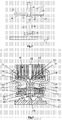
- the dual clutch shown in Figure 1 and generally designated 1 has a clutch housing 2, which is non-rotatably connected via a Torsionsdämpferatti 3 to a coupling flange 4 with a drive shaft 5 of a motor, not shown here.
- the torque of the motor is transmitted via the drive shaft 5, the coupling flange 4 and the clutch housing 2 to a clutch housing cover 6 which is rotatably connected to a two-part clutch hub 7.
- the clutch hub 7 is rotatably supported about a fixed clutch shaft 8, which is fixedly connected to a housing 9 of a transmission, of which in the figure 1 nor a transmission input shaft 10 and a second transmission input shaft 11 is shown.
- the second transmission input shaft 11 is formed as a hollow shaft which is arranged coaxially with the first transmission input shaft 10.
- the fixed clutch axle 8 has the task of distributing oil, which is supplied from the transmission, in the dual clutch 1.
- a plurality of annular oil passages 12 are formed in the coupling axis 8, of which the oil flows into a system of oil holes 13.
- the first transmission input shaft 10 is rotatably connected to a first outer clutch pot 14.
- the clutch pot 14 has a first outer disk carrier 16 for the rotationally fixed reception of outer disks 17 of a first friction clutch 18.
- a second, inner clutch pot 19, which is arranged in the outer clutch pot 14, likewise has a second outer disk carrier 21 on a pot rim 20, which holds outer disks 22 of a second clutch 23 in a rotationally fixed manner in the inner clutch pot 19.
- the first friction clutch 18 and the second friction clutch 23 have, in addition to the outer disks 17, 22 in each case inner disks, which are identical for both friction clutches 18, 23 and are designated by 24.
- the inner plates 24 are rotatably connected via a coupling web 25 with the clutch hub 7.
- the coupling web 25 in this case comprises a first inner disk carrier 26 for receiving the inner disk of the first friction clutch 18, a second inner disk carrier 27 for receiving the inner disk of the second friction clutch 23 and a pressure plate 28th
- the inner disk carrier 26 comprises a carrier part 29 extending in the axial direction and a connecting piece 30 extending perpendicular thereto, extending in the radial direction, which connects the clutch hub 7 to the carrier part 29.
- the inner disk carrier 26 is formed in one piece and can be produced by sheet metal forming.
- the inner disk carrier 27 has a carrier part and a connecting piece, which are also designated 29 and 30 due to the identical structure as in the first inner disk carrier 26.
- the inner disk carrier 26, 27 are constructed identical to each other and arranged back to back.
- the pressure plate 28 has an inner diameter 31 which corresponds approximately to an inner diameter 32 of the inner disks 24.
- the pressure plate 28 is fixed without play between the plate carrier 26 and the plate carrier 27 and is centered by two annular shoulders 33 (see Figure 2) to the clutch hub 7.
- the plate carriers 26, 27 are held together by individual welds or a circumferential weld 34 (see FIG. 2).
- a piston-cylinder unit 35 is pressurized, so that against the force of a spring 36 via a pressure plate 37, the outer disk 17 and the inner disk 24 of the first friction clutch 18 are compressed.
- the pressure plate 28 serves as an abutment for the compressed blades 17, 24. Due to the voltage applied to the disc-shaped pressure plate 28 pressure, the connecting pieces 30 of the first and second inner disc carrier 26, 27 are subjected to bending. It is therefore necessary to make the two connecting pieces 30 so rigid that the coupling web 25 is not excessively deformed due to the pressure applied to the pressure plate 28.
- the piston-cylinder unit 35 comprises an axially displaceable piston 41 which delimits an annular working chamber 42 in which the pressure for actuating the first friction clutch 18 is built up.
- oil is introduced in the working chamber 42 radially from the inside with a predetermined pressure.
- a compensation chamber 43 is provided, which is also annular and laterally bounded by a compensation cover 44.
- the compensation cover 44 is connected to the piston 41.
- the pressure caused by centrifugal forces in the compensation chamber pressure pushes the balance cover 44 and thus also the piston 41 away from the coupling web 25, so that the compression of the fins of the first friction clutch is at least partially compensated or overcompensated due to the centrifugal forces acting on the oil. This applies analogously to the second friction clutch.
- FIG. 2 shows a second embodiment, in which case only the clutch hub 7 and the coupling web 25 with the inner disk carrier 26, 27 and the pressure plate 28 are shown.
- the connecting pieces 30 of the inner disk carrier 26, 28 have bulges 38.
- a plurality of bulges 38 are provided on a connecting piece, which are spaced apart in the circumferential direction and by areas without bulges (see dashed line) are separated from each other.
- the connecting pieces 30 converge again at a foot end 39 and are connected there to the coupling hub 7 via welds 40.
- the bulges 40 may alternatively extend to the clutch hub 7, that is, the connectors 30 do not run together at the foot end, but meet spaced from each other on the clutch hub 7 (not shown).
- a coupling hub piece may be integrally connected to the connecting piece 30 of the inner disk carrier 27, 28 in each case, which replaces at least part of the coupling hub 7 or assumes partial functions of the coupling hub 7.
- Figure 3 shows a further embodiment of the invention, wherein, similar to Figure 2, only individual components are shown.
- a cutting disc 45 is arranged, which extends in the radial direction from the clutch hub 7 to the pressure plate 28 and a chamber 46 between the inner disk carrier 26, 27 into a first sub-chamber 47 and a second sub-chamber 48 shares.
- the inner disk carrier 26, 27 are laterally welded to a radially outwardly projecting collar 49 of the coupling web 7.
- a plurality of recesses 50 are incorporated on the circumference, are formed by the plurality of gaps between the collar 49 and respective inner disk carrier 26, 27.
- oil can be supplied into the first or second sub-chambers 47, 48, which flows through openings 51 on the respective carrier parts 29 of the inner disk carriers 26, 27 and cools the disk sets of the two friction clutches 18, 23. Due to the cutting disc 45, the first and the second friction clutch can be acted upon with different sized cooling currents.
- the pressure plate 28 has an annular shoulder 52 on which the cutting disc 45 abuts.
- the collar 49 is also a paragraph 53 as a further investment for the cutting disc 45 is provided.
- the cutting disk 45 is welded to inwardly drawn indentations or indentations 54 of the inner disk carriers 26, 27 with these.
- the inner disk carrier 26 and the piston 41 in this embodiment form the walls of the compensation chamber 43 (see FIG. 1), by which compression of the disks of the first friction clutch due to centrifugal forces is prevented (see description of FIG. 1).
- the compensation chamber 43 there is also the spring 36, which presses the piston 41 outwards again after the first friction clutch 18 has been actuated.
- a compensation chamber is also provided in a game symmetrical arrangement.
Landscapes
- Engineering & Computer Science (AREA)
- General Engineering & Computer Science (AREA)
- Mechanical Engineering (AREA)
- Hydraulic Clutches, Magnetic Clutches, Fluid Clutches, And Fluid Joints (AREA)
- Mechanical Operated Clutches (AREA)
Priority Applications (1)
| Application Number | Priority Date | Filing Date | Title |
|---|---|---|---|
| EP05100518.9A EP1686276B1 (fr) | 2005-01-27 | 2005-01-27 | Embrayage double avec âme intermédiaire |
Applications Claiming Priority (1)
| Application Number | Priority Date | Filing Date | Title |
|---|---|---|---|
| EP05100518.9A EP1686276B1 (fr) | 2005-01-27 | 2005-01-27 | Embrayage double avec âme intermédiaire |
Publications (2)
| Publication Number | Publication Date |
|---|---|
| EP1686276A1 true EP1686276A1 (fr) | 2006-08-02 |
| EP1686276B1 EP1686276B1 (fr) | 2017-07-26 |
Family
ID=34938583
Family Applications (1)
| Application Number | Title | Priority Date | Filing Date |
|---|---|---|---|
| EP05100518.9A Expired - Lifetime EP1686276B1 (fr) | 2005-01-27 | 2005-01-27 | Embrayage double avec âme intermédiaire |
Country Status (1)
| Country | Link |
|---|---|
| EP (1) | EP1686276B1 (fr) |
Cited By (12)
| Publication number | Priority date | Publication date | Assignee | Title |
|---|---|---|---|---|
| DE102008048801B3 (de) * | 2008-09-24 | 2010-06-17 | Getrag Ford Transmissions Gmbh | Abstützelement für eine Kupplungsvorrichtung mit zwei Reibkupplungen |
| EP1950440B2 (fr) † | 2007-01-26 | 2013-11-13 | Hoerbiger Antriebstechnik GmbH | Procédé de fabrication d'un panier d'embrayage d'un embrayage double |
| WO2014012542A1 (fr) * | 2012-07-20 | 2014-01-23 | Schaeffler Technologies AG & Co. KG | Embrayage double |
| WO2014015868A1 (fr) * | 2012-07-20 | 2014-01-30 | Schaeffler Technologies AG & Co. KG | Ensemble embrayage double |
| CN103573881A (zh) * | 2012-07-18 | 2014-02-12 | 舍弗勒技术股份两合公司 | 双离合器装置 |
| DE102012013873A1 (de) * | 2012-07-12 | 2014-05-15 | Getrag Getriebe- Und Zahnradfabrik Hermann Hagenmeyer Gmbh & Cie Kg | Lamellenträger-Lageranordnung und Kupplungsanordnung für einen Kraftfahrzeugantriebsstrang |
| CN103883638A (zh) * | 2012-12-21 | 2014-06-25 | 舍弗勒技术股份两合公司 | 用于可松脱地连接一输入轴与两输出轴的双离合器 |
| DE102014219621A1 (de) * | 2014-09-26 | 2016-03-31 | Volkswagen Aktiengesellschaft | Mehrfachkupplung für ein Kraftfahrzeuggetriebe |
| EP2732174B1 (fr) | 2011-07-15 | 2017-08-09 | Schaeffler Technologies AG & Co. KG | Double embrayage |
| EP2603710A4 (fr) * | 2010-08-12 | 2018-04-18 | Borgwarner Inc. | Unité de double embrayage parallèle |
| DE102008045791B4 (de) * | 2007-11-11 | 2020-08-06 | Saic Motor Corp. Ltd. | Doppelkupplungsgetriebe und Verfahren zur Montage eines Doppelkupplungsgetriebes |
| CN114402146A (zh) * | 2019-08-02 | 2022-04-26 | 株式会社法雷奥凯佩科 | 双离合器装置 |
Families Citing this family (1)
| Publication number | Priority date | Publication date | Assignee | Title |
|---|---|---|---|---|
| EP4707631A1 (fr) * | 2024-09-09 | 2026-03-11 | Transmisiones Y Equipos Mecánicos, S.A. de C.V. | Unité d'embrayage double parallèle compacte |
Citations (6)
| Publication number | Priority date | Publication date | Assignee | Title |
|---|---|---|---|---|
| DE9114528U1 (de) * | 1991-11-22 | 1992-02-13 | Zahnradfabrik Friedrichshafen Ag, 7990 Friedrichshafen | Doppelkupplung |
| JPH10281178A (ja) * | 1997-04-04 | 1998-10-20 | Nsk Warner Kk | クラッチ用ピストンの製造方法 |
| EP1195537A1 (fr) | 2000-10-05 | 2002-04-10 | Ford Global Technologies, Inc., A subsidiary of Ford Motor Company | Double embrayage pour une transmission avec deux arbres d'entrée |
| DE10146606A1 (de) * | 2001-09-21 | 2003-04-10 | Zf Sachs Ag | Mehrfach-Kupplungseinrichtung mit axial nebeneinander angeordneten Lamellen-Kupplungsanordnungen |
| WO2004104439A1 (fr) | 2003-05-24 | 2004-12-02 | Dr. Ing. H.C. F. Porsche Aktiengesellschaft | Dispositif d'embrayage, en particulier embrayage a disques pour une boite de vitesses a embrayage double |
| EP1522753A1 (fr) | 2003-10-11 | 2005-04-13 | BorgWarner Inc. | Embrayage double hydraulique |
-
2005
- 2005-01-27 EP EP05100518.9A patent/EP1686276B1/fr not_active Expired - Lifetime
Patent Citations (7)
| Publication number | Priority date | Publication date | Assignee | Title |
|---|---|---|---|---|
| DE9114528U1 (de) * | 1991-11-22 | 1992-02-13 | Zahnradfabrik Friedrichshafen Ag, 7990 Friedrichshafen | Doppelkupplung |
| JPH10281178A (ja) * | 1997-04-04 | 1998-10-20 | Nsk Warner Kk | クラッチ用ピストンの製造方法 |
| EP1195537A1 (fr) | 2000-10-05 | 2002-04-10 | Ford Global Technologies, Inc., A subsidiary of Ford Motor Company | Double embrayage pour une transmission avec deux arbres d'entrée |
| US20040206599A1 (en) * | 2000-10-05 | 2004-10-21 | Andreas Hegerath | Dual clutch for a transmission with two input shafts |
| DE10146606A1 (de) * | 2001-09-21 | 2003-04-10 | Zf Sachs Ag | Mehrfach-Kupplungseinrichtung mit axial nebeneinander angeordneten Lamellen-Kupplungsanordnungen |
| WO2004104439A1 (fr) | 2003-05-24 | 2004-12-02 | Dr. Ing. H.C. F. Porsche Aktiengesellschaft | Dispositif d'embrayage, en particulier embrayage a disques pour une boite de vitesses a embrayage double |
| EP1522753A1 (fr) | 2003-10-11 | 2005-04-13 | BorgWarner Inc. | Embrayage double hydraulique |
Non-Patent Citations (1)
| Title |
|---|
| PATENT ABSTRACTS OF JAPAN vol. 1999, no. 01 29 January 1999 (1999-01-29) * |
Cited By (19)
| Publication number | Priority date | Publication date | Assignee | Title |
|---|---|---|---|---|
| EP1950440B2 (fr) † | 2007-01-26 | 2013-11-13 | Hoerbiger Antriebstechnik GmbH | Procédé de fabrication d'un panier d'embrayage d'un embrayage double |
| DE102008045791B4 (de) * | 2007-11-11 | 2020-08-06 | Saic Motor Corp. Ltd. | Doppelkupplungsgetriebe und Verfahren zur Montage eines Doppelkupplungsgetriebes |
| CN101915276A (zh) * | 2008-09-24 | 2010-12-15 | 格特拉克·福特传动系统有限公司 | 用于具有两个摩擦离合器的离合器装置的支撑元件 |
| CN101915276B (zh) * | 2008-09-24 | 2013-08-28 | 格特拉克·福特传动系统有限公司 | 用于具有两个摩擦离合器的离合器装置的支撑元件 |
| DE102008048801B3 (de) * | 2008-09-24 | 2010-06-17 | Getrag Ford Transmissions Gmbh | Abstützelement für eine Kupplungsvorrichtung mit zwei Reibkupplungen |
| EP2603710A4 (fr) * | 2010-08-12 | 2018-04-18 | Borgwarner Inc. | Unité de double embrayage parallèle |
| EP2732174B1 (fr) | 2011-07-15 | 2017-08-09 | Schaeffler Technologies AG & Co. KG | Double embrayage |
| DE102012013873B4 (de) | 2012-07-12 | 2019-03-28 | GETRAG B.V. & Co. KG | Lamellenträger-Lageranordnung und Kupplungsanordnung für einen Kraftfahrzeugantriebsstrang |
| DE102012013873A1 (de) * | 2012-07-12 | 2014-05-15 | Getrag Getriebe- Und Zahnradfabrik Hermann Hagenmeyer Gmbh & Cie Kg | Lamellenträger-Lageranordnung und Kupplungsanordnung für einen Kraftfahrzeugantriebsstrang |
| CN103573881A (zh) * | 2012-07-18 | 2014-02-12 | 舍弗勒技术股份两合公司 | 双离合器装置 |
| CN104471267A (zh) * | 2012-07-20 | 2015-03-25 | 舍弗勒技术股份两合公司 | 双离合器装置 |
| CN104428548A (zh) * | 2012-07-20 | 2015-03-18 | 舍弗勒技术股份两合公司 | 双离合器 |
| WO2014015868A1 (fr) * | 2012-07-20 | 2014-01-30 | Schaeffler Technologies AG & Co. KG | Ensemble embrayage double |
| WO2014012542A1 (fr) * | 2012-07-20 | 2014-01-23 | Schaeffler Technologies AG & Co. KG | Embrayage double |
| CN103883638A (zh) * | 2012-12-21 | 2014-06-25 | 舍弗勒技术股份两合公司 | 用于可松脱地连接一输入轴与两输出轴的双离合器 |
| CN103883638B (zh) * | 2012-12-21 | 2019-06-18 | 舍弗勒技术股份两合公司 | 用于可松脱地连接一输入轴与两输出轴的双离合器 |
| CN105465214A (zh) * | 2014-09-26 | 2016-04-06 | 大众汽车有限公司 | 用于机动车变速器的多重离合器 |
| DE102014219621A1 (de) * | 2014-09-26 | 2016-03-31 | Volkswagen Aktiengesellschaft | Mehrfachkupplung für ein Kraftfahrzeuggetriebe |
| CN114402146A (zh) * | 2019-08-02 | 2022-04-26 | 株式会社法雷奥凯佩科 | 双离合器装置 |
Also Published As
| Publication number | Publication date |
|---|---|
| EP1686276B1 (fr) | 2017-07-26 |
Similar Documents
| Publication | Publication Date | Title |
|---|---|---|
| EP2685122B1 (fr) | Agencement de palier pour support de disques et embrayage pour un groupe motopropulseur d'un véhicule automobile | |
| DE10034677B4 (de) | Mehrfachkupplungsanordnung | |
| DE102004012948B4 (de) | Doppelkupplungseinrichtung in axialer Bauart | |
| DE2657306A1 (de) | Vibrationsdaempfer | |
| EP2732174B1 (fr) | Double embrayage | |
| EP1686276B1 (fr) | Embrayage double avec âme intermédiaire | |
| DE102018211377B4 (de) | Rotorträger für eine elektrische Maschine | |
| WO2012045297A1 (fr) | Double embrayage | |
| DE10319415A1 (de) | Hydrodynamischer Momentwandler, insbesondere für Kraftfahrzeuge | |
| EP2732175B1 (fr) | Assemblage d'un dispositif de débrayage et d'une cloche d'embrayage | |
| DE3418558C1 (de) | Einstellbare Reibungsschlupfkupplung | |
| EP2853773B1 (fr) | Amortisseur d'oscillations de torsion | |
| DE102018211374B4 (de) | Rotorträger für eine elektrische Maschine | |
| DE102018211376B4 (de) | Rotorträger für eine elektrische Maschine | |
| WO2021228303A1 (fr) | Ensemble d'embrayage multidisques ayant des unités de plaque de ressort à action indépendante pour relier deux disques de composant à un arbre de sortie | |
| EP1678429A1 (fr) | Ensemble embrayage dans une boite de vitesses equipee de deux embrayages voisins dans le sens axial et radial | |
| DE102015208369A1 (de) | Kupplungsanordnung | |
| EP1686277B1 (fr) | Embrayage double à disques de même dimension | |
| DE102015225034A1 (de) | Lamellenträgerverbindung | |
| DE19636398B4 (de) | Kupplungsdeckel für eine Kupplung und Kupplungsmechanismus mit einem solchen Deckel | |
| WO2012155877A1 (fr) | Système d'embrayage pour tracteurs à prise de force | |
| EP2853771B1 (fr) | Amortisseur d'oscillations de torsion | |
| DE19754652A1 (de) | Drehmomentwandler | |
| WO2018091022A1 (fr) | Dispositif de transmission de couple | |
| EP3500767B1 (fr) | Embrayage à friction |
Legal Events
| Date | Code | Title | Description |
|---|---|---|---|
| PUAI | Public reference made under article 153(3) epc to a published international application that has entered the european phase |
Free format text: ORIGINAL CODE: 0009012 |
|
| AK | Designated contracting states |
Kind code of ref document: A1 Designated state(s): AT BE BG CH CY CZ DE DK EE ES FI FR GB GR HU IE IS IT LI LT LU MC NL PL PT RO SE SI SK TR |
|
| AX | Request for extension of the european patent |
Extension state: AL BA HR LV MK YU |
|
| 17P | Request for examination filed |
Effective date: 20070202 |
|
| AKX | Designation fees paid |
Designated state(s): AT BE BG CH CY CZ DE DK EE ES FI FR GB GR HU IE IS IT LI LT LU MC NL PL PT RO SE SI SK TR |
|
| 17Q | First examination report despatched |
Effective date: 20091210 |
|
| GRAP | Despatch of communication of intention to grant a patent |
Free format text: ORIGINAL CODE: EPIDOSNIGR1 |
|
| INTG | Intention to grant announced |
Effective date: 20170220 |
|
| GRAS | Grant fee paid |
Free format text: ORIGINAL CODE: EPIDOSNIGR3 |
|
| GRAA | (expected) grant |
Free format text: ORIGINAL CODE: 0009210 |
|
| AK | Designated contracting states |
Kind code of ref document: B1 Designated state(s): AT BE BG CH CY CZ DE DK EE ES FI FR GB GR HU IE IS IT LI LT LU MC NL PL PT RO SE SI SK TR |
|
| REG | Reference to a national code |
Ref country code: GB Ref legal event code: FG4D Free format text: NOT ENGLISH |
|
| REG | Reference to a national code |
Ref country code: CH Ref legal event code: EP |
|
| REG | Reference to a national code |
Ref country code: AT Ref legal event code: REF Ref document number: 912657 Country of ref document: AT Kind code of ref document: T Effective date: 20170815 |
|
| REG | Reference to a national code |
Ref country code: IE Ref legal event code: FG4D Free format text: LANGUAGE OF EP DOCUMENT: GERMAN |
|
| REG | Reference to a national code |
Ref country code: DE Ref legal event code: R096 Ref document number: 502005015656 Country of ref document: DE |
|
| REG | Reference to a national code |
Ref country code: NL Ref legal event code: MP Effective date: 20170726 |
|
| REG | Reference to a national code |
Ref country code: LT Ref legal event code: MG4D |
|
| PG25 | Lapsed in a contracting state [announced via postgrant information from national office to epo] |
Ref country code: SE Free format text: LAPSE BECAUSE OF FAILURE TO SUBMIT A TRANSLATION OF THE DESCRIPTION OR TO PAY THE FEE WITHIN THE PRESCRIBED TIME-LIMIT Effective date: 20170726 Ref country code: FI Free format text: LAPSE BECAUSE OF FAILURE TO SUBMIT A TRANSLATION OF THE DESCRIPTION OR TO PAY THE FEE WITHIN THE PRESCRIBED TIME-LIMIT Effective date: 20170726 Ref country code: NL Free format text: LAPSE BECAUSE OF FAILURE TO SUBMIT A TRANSLATION OF THE DESCRIPTION OR TO PAY THE FEE WITHIN THE PRESCRIBED TIME-LIMIT Effective date: 20170726 Ref country code: LT Free format text: LAPSE BECAUSE OF FAILURE TO SUBMIT A TRANSLATION OF THE DESCRIPTION OR TO PAY THE FEE WITHIN THE PRESCRIBED TIME-LIMIT Effective date: 20170726 |
|
| PG25 | Lapsed in a contracting state [announced via postgrant information from national office to epo] |
Ref country code: ES Free format text: LAPSE BECAUSE OF FAILURE TO SUBMIT A TRANSLATION OF THE DESCRIPTION OR TO PAY THE FEE WITHIN THE PRESCRIBED TIME-LIMIT Effective date: 20170726 Ref country code: GR Free format text: LAPSE BECAUSE OF FAILURE TO SUBMIT A TRANSLATION OF THE DESCRIPTION OR TO PAY THE FEE WITHIN THE PRESCRIBED TIME-LIMIT Effective date: 20171027 Ref country code: BG Free format text: LAPSE BECAUSE OF FAILURE TO SUBMIT A TRANSLATION OF THE DESCRIPTION OR TO PAY THE FEE WITHIN THE PRESCRIBED TIME-LIMIT Effective date: 20171026 Ref country code: PL Free format text: LAPSE BECAUSE OF FAILURE TO SUBMIT A TRANSLATION OF THE DESCRIPTION OR TO PAY THE FEE WITHIN THE PRESCRIBED TIME-LIMIT Effective date: 20170726 Ref country code: IS Free format text: LAPSE BECAUSE OF FAILURE TO SUBMIT A TRANSLATION OF THE DESCRIPTION OR TO PAY THE FEE WITHIN THE PRESCRIBED TIME-LIMIT Effective date: 20171126 |
|
| REG | Reference to a national code |
Ref country code: FR Ref legal event code: PLFP Year of fee payment: 14 |
|
| PG25 | Lapsed in a contracting state [announced via postgrant information from national office to epo] |
Ref country code: RO Free format text: LAPSE BECAUSE OF FAILURE TO SUBMIT A TRANSLATION OF THE DESCRIPTION OR TO PAY THE FEE WITHIN THE PRESCRIBED TIME-LIMIT Effective date: 20170726 Ref country code: DK Free format text: LAPSE BECAUSE OF FAILURE TO SUBMIT A TRANSLATION OF THE DESCRIPTION OR TO PAY THE FEE WITHIN THE PRESCRIBED TIME-LIMIT Effective date: 20170726 Ref country code: CZ Free format text: LAPSE BECAUSE OF FAILURE TO SUBMIT A TRANSLATION OF THE DESCRIPTION OR TO PAY THE FEE WITHIN THE PRESCRIBED TIME-LIMIT Effective date: 20170726 |
|
| REG | Reference to a national code |
Ref country code: DE Ref legal event code: R097 Ref document number: 502005015656 Country of ref document: DE |
|
| PG25 | Lapsed in a contracting state [announced via postgrant information from national office to epo] |
Ref country code: EE Free format text: LAPSE BECAUSE OF FAILURE TO SUBMIT A TRANSLATION OF THE DESCRIPTION OR TO PAY THE FEE WITHIN THE PRESCRIBED TIME-LIMIT Effective date: 20170726 Ref country code: SK Free format text: LAPSE BECAUSE OF FAILURE TO SUBMIT A TRANSLATION OF THE DESCRIPTION OR TO PAY THE FEE WITHIN THE PRESCRIBED TIME-LIMIT Effective date: 20170726 Ref country code: IT Free format text: LAPSE BECAUSE OF FAILURE TO SUBMIT A TRANSLATION OF THE DESCRIPTION OR TO PAY THE FEE WITHIN THE PRESCRIBED TIME-LIMIT Effective date: 20170726 |
|
| PLBE | No opposition filed within time limit |
Free format text: ORIGINAL CODE: 0009261 |
|
| STAA | Information on the status of an ep patent application or granted ep patent |
Free format text: STATUS: NO OPPOSITION FILED WITHIN TIME LIMIT |
|
| 26N | No opposition filed |
Effective date: 20180430 |
|
| PG25 | Lapsed in a contracting state [announced via postgrant information from national office to epo] |
Ref country code: SI Free format text: LAPSE BECAUSE OF FAILURE TO SUBMIT A TRANSLATION OF THE DESCRIPTION OR TO PAY THE FEE WITHIN THE PRESCRIBED TIME-LIMIT Effective date: 20170726 |
|
| REG | Reference to a national code |
Ref country code: CH Ref legal event code: PL |
|
| PG25 | Lapsed in a contracting state [announced via postgrant information from national office to epo] |
Ref country code: LU Free format text: LAPSE BECAUSE OF NON-PAYMENT OF DUE FEES Effective date: 20180127 |
|
| REG | Reference to a national code |
Ref country code: IE Ref legal event code: MM4A |
|
| REG | Reference to a national code |
Ref country code: BE Ref legal event code: MM Effective date: 20180131 |
|
| PG25 | Lapsed in a contracting state [announced via postgrant information from national office to epo] |
Ref country code: BE Free format text: LAPSE BECAUSE OF NON-PAYMENT OF DUE FEES Effective date: 20180131 Ref country code: LI Free format text: LAPSE BECAUSE OF NON-PAYMENT OF DUE FEES Effective date: 20180131 Ref country code: CH Free format text: LAPSE BECAUSE OF NON-PAYMENT OF DUE FEES Effective date: 20180131 |
|
| PG25 | Lapsed in a contracting state [announced via postgrant information from national office to epo] |
Ref country code: IE Free format text: LAPSE BECAUSE OF NON-PAYMENT OF DUE FEES Effective date: 20180127 |
|
| REG | Reference to a national code |
Ref country code: AT Ref legal event code: MM01 Ref document number: 912657 Country of ref document: AT Kind code of ref document: T Effective date: 20180127 |
|
| PG25 | Lapsed in a contracting state [announced via postgrant information from national office to epo] |
Ref country code: AT Free format text: LAPSE BECAUSE OF NON-PAYMENT OF DUE FEES Effective date: 20180127 |
|
| PG25 | Lapsed in a contracting state [announced via postgrant information from national office to epo] |
Ref country code: MC Free format text: LAPSE BECAUSE OF FAILURE TO SUBMIT A TRANSLATION OF THE DESCRIPTION OR TO PAY THE FEE WITHIN THE PRESCRIBED TIME-LIMIT Effective date: 20170726 |
|
| PG25 | Lapsed in a contracting state [announced via postgrant information from national office to epo] |
Ref country code: TR Free format text: LAPSE BECAUSE OF FAILURE TO SUBMIT A TRANSLATION OF THE DESCRIPTION OR TO PAY THE FEE WITHIN THE PRESCRIBED TIME-LIMIT Effective date: 20170726 |
|
| PG25 | Lapsed in a contracting state [announced via postgrant information from national office to epo] |
Ref country code: HU Free format text: LAPSE BECAUSE OF FAILURE TO SUBMIT A TRANSLATION OF THE DESCRIPTION OR TO PAY THE FEE WITHIN THE PRESCRIBED TIME-LIMIT; INVALID AB INITIO Effective date: 20050127 Ref country code: PT Free format text: LAPSE BECAUSE OF FAILURE TO SUBMIT A TRANSLATION OF THE DESCRIPTION OR TO PAY THE FEE WITHIN THE PRESCRIBED TIME-LIMIT Effective date: 20170726 |
|
| PG25 | Lapsed in a contracting state [announced via postgrant information from national office to epo] |
Ref country code: CY Free format text: LAPSE BECAUSE OF FAILURE TO SUBMIT A TRANSLATION OF THE DESCRIPTION OR TO PAY THE FEE WITHIN THE PRESCRIBED TIME-LIMIT Effective date: 20170726 |
|
| PGFP | Annual fee paid to national office [announced via postgrant information from national office to epo] |
Ref country code: GB Payment date: 20201231 Year of fee payment: 17 Ref country code: FR Payment date: 20201223 Year of fee payment: 17 |
|
| PGFP | Annual fee paid to national office [announced via postgrant information from national office to epo] |
Ref country code: DE Payment date: 20201218 Year of fee payment: 17 |
|
| REG | Reference to a national code |
Ref country code: DE Ref legal event code: R119 Ref document number: 502005015656 Country of ref document: DE |
|
| GBPC | Gb: european patent ceased through non-payment of renewal fee |
Effective date: 20220127 |
|
| PG25 | Lapsed in a contracting state [announced via postgrant information from national office to epo] |
Ref country code: GB Free format text: LAPSE BECAUSE OF NON-PAYMENT OF DUE FEES Effective date: 20220127 Ref country code: DE Free format text: LAPSE BECAUSE OF NON-PAYMENT OF DUE FEES Effective date: 20220802 |
|
| PG25 | Lapsed in a contracting state [announced via postgrant information from national office to epo] |
Ref country code: FR Free format text: LAPSE BECAUSE OF NON-PAYMENT OF DUE FEES Effective date: 20220131 |