EP1686320A2 - Absorbeur de bruits pour un appareil de chauffage - Google Patents
Absorbeur de bruits pour un appareil de chauffage Download PDFInfo
- Publication number
- EP1686320A2 EP1686320A2 EP05111815A EP05111815A EP1686320A2 EP 1686320 A2 EP1686320 A2 EP 1686320A2 EP 05111815 A EP05111815 A EP 05111815A EP 05111815 A EP05111815 A EP 05111815A EP 1686320 A2 EP1686320 A2 EP 1686320A2
- Authority
- EP
- European Patent Office
- Prior art keywords
- flow
- flow channel
- exhaust
- gas
- fuel
- Prior art date
- Legal status (The legal status is an assumption and is not a legal conclusion. Google has not performed a legal analysis and makes no representation as to the accuracy of the status listed.)
- Withdrawn
Links
- 239000006096 absorbing agent Substances 0.000 title claims abstract description 13
- 238000010438 heat treatment Methods 0.000 title description 2
- 239000000203 mixture Substances 0.000 claims abstract description 8
- 238000013016 damping Methods 0.000 claims description 15
- 238000010521 absorption reaction Methods 0.000 abstract description 3
- 230000005284 excitation Effects 0.000 abstract 1
- 239000000446 fuel Substances 0.000 abstract 1
- 238000002485 combustion reaction Methods 0.000 description 7
- 238000001228 spectrum Methods 0.000 description 2
- 238000005452 bending Methods 0.000 description 1
- 238000011161 development Methods 0.000 description 1
- 230000018109 developmental process Effects 0.000 description 1
- 238000010586 diagram Methods 0.000 description 1
- 230000003993 interaction Effects 0.000 description 1
- 239000012528 membrane Substances 0.000 description 1
- 239000012858 resilient material Substances 0.000 description 1
- 230000007704 transition Effects 0.000 description 1
Images
Classifications
-
- F—MECHANICAL ENGINEERING; LIGHTING; HEATING; WEAPONS; BLASTING
- F23—COMBUSTION APPARATUS; COMBUSTION PROCESSES
- F23M—CASINGS, LININGS, WALLS OR DOORS SPECIALLY ADAPTED FOR COMBUSTION CHAMBERS, e.g. FIREBRIDGES; DEVICES FOR DEFLECTING AIR, FLAMES OR COMBUSTION PRODUCTS IN COMBUSTION CHAMBERS; SAFETY ARRANGEMENTS SPECIALLY ADAPTED FOR COMBUSTION APPARATUS; DETAILS OF COMBUSTION CHAMBERS, NOT OTHERWISE PROVIDED FOR
- F23M9/00—Baffles or deflectors for air or combustion products; Flame shields
- F23M9/06—Baffles or deflectors for air or combustion products; Flame shields in fire-boxes
-
- F—MECHANICAL ENGINEERING; LIGHTING; HEATING; WEAPONS; BLASTING
- F23—COMBUSTION APPARATUS; COMBUSTION PROCESSES
- F23M—CASINGS, LININGS, WALLS OR DOORS SPECIALLY ADAPTED FOR COMBUSTION CHAMBERS, e.g. FIREBRIDGES; DEVICES FOR DEFLECTING AIR, FLAMES OR COMBUSTION PRODUCTS IN COMBUSTION CHAMBERS; SAFETY ARRANGEMENTS SPECIALLY ADAPTED FOR COMBUSTION APPARATUS; DETAILS OF COMBUSTION CHAMBERS, NOT OTHERWISE PROVIDED FOR
- F23M20/00—Details of combustion chambers, not otherwise provided for, e.g. means for storing heat from flames
- F23M20/005—Noise absorbing means
-
- F—MECHANICAL ENGINEERING; LIGHTING; HEATING; WEAPONS; BLASTING
- F23—COMBUSTION APPARATUS; COMBUSTION PROCESSES
- F23J—REMOVAL OR TREATMENT OF COMBUSTION PRODUCTS OR COMBUSTION RESIDUES; FLUES
- F23J2900/00—Special arrangements for conducting or purifying combustion fumes; Treatment of fumes or ashes
- F23J2900/13003—Means for reducing the noise in smoke conducing ducts or systems
Definitions
- the invention relates to a heater with a sound damping device according to the preamble of claim 1.
- EP 723 123 B1 discloses a heating device with a sound damping device associated with the exhaust system, the sound damping device being formed by a flexible wall part formed in the exhaust system, which as a mechanical resonator has a very low impedance for the required frequency range.
- a similar sound damping device is known from DE 196 12 987 A1, in which a wall portion of an exhaust pipe, a supply air duct of a mixture supply duct, a burner hood or an exhaust manifold is made yielding.
- the compliance is designed so that either the entire wall or parts of the wall are made by a resilient material.
- it is also provided to carry out in the wall a hole which is covered with a membrane.
- the present invention has for its object to provide a sound damping device for a heater, which is simple and which requires less space.
- the object of the invention is achieved with the characterizing features of claim 1.
- the heater with the sound damping device according to the invention has the advantage that the combustion chamber vibrations in the intake and / or in the exhaust path can be effectively suppressed.
- the sound damping device requires no significant additional space.
- the flow cross section remains substantially unrestricted both in the intake path for the mixture supply and in the exhaust gas path for the exhaust gas.
- a cavity is formed as a damping chamber, which is in communication via the inlet openings and at least one outflow opening with the gas flow in the flow channel.
- the outflow opening expediently in the flow direction of the gas flow behind the flow deflection in the flow channel.
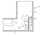
- FIG. 1 shows a section of a schematic diagram of a sound damping device in the intake of a heater.
- the intake passage shown in the figure represents a flow channel 10 for a fuel-air mixture of a heater, not shown.
- the flow channel 10 leads to a burner, not shown, which burns the fuel-air mixture and the exhaust gas via a heat exchanger, not shown in a likewise not illustrated exhaust pipe leads.
- the flow channel 10 has a first flow guide section 11 and a second flow guide section 12. Between the two flow guide sections 11 and 12, for example, a 90-degree flow deflection 13 is formed for the fuel-air mixture.
- a vibration absorber 20 is arranged as a sound damping device in the outer angle at the transition from the flow guide section 11 to the Strömungsbowungsabêt 12 within the flow channel 10.
- the vibration absorber 20 has a side wall 21 which points into the flow channel 10 and into which a plurality of inlet openings 22 are introduced.
- the flow direction of the gas flow in the flow channel 10 is shown by arrows.
- a cavity 23 is formed as a damping chamber, which via the inflow opening 22nd as well as via a further outflow opening 24 communicates with the flow channel 10 in connection.
- the outflow opening 24 points in the flow direction of the gas flow behind the flow deflection 13 into the second flow guiding section 12 downstream of the flow deflection 13.
- vibration absorber 20 in the exhaust path of the heater in a flow deflection as well. Moreover, it is also conceivable to arrange the flow absorber 20 both in the intake and in the exhaust path of a heater. In addition, an embodiment is conceivable in which a plurality of vibration absorbers 20 are arranged in the intake path and / or in the exhaust path.
- the natural frequency of the passive vibration absorber 20 corresponds to the frequency of the combustion chamber vibrations.
- the inflow openings 22 in the side wall 21 of the vibration absorber 20 serve to achieve a broadband absorption characteristic.
- the vibration absorber 20 serves to suppress the combustion chamber vibrations.
- the side wall 21 In order to achieve a broadband sound absorption, it is expedient to carry out the side wall 21 as a thin-walled, perforated shell structure.
- the resonance parameters are thereby formed by the thickness and the bending stiffness of the side wall 21, the depth of the space 23, the flow velocity in the inflow openings 22 and the area ratio of the inflow openings 22 to the total area of the side wall 21. It was found that for small inlet openings 22 in the side wall 21 with a diameter of 0.5 mm to 1 mm, a significant increase in the frequency spectrum can be achieved.
Landscapes
- Engineering & Computer Science (AREA)
- Chemical & Material Sciences (AREA)
- Combustion & Propulsion (AREA)
- Mechanical Engineering (AREA)
- General Engineering & Computer Science (AREA)
- Chimneys And Flues (AREA)
Applications Claiming Priority (1)
| Application Number | Priority Date | Filing Date | Title |
|---|---|---|---|
| DE102005004079A DE102005004079B4 (de) | 2005-01-28 | 2005-01-28 | Schalldämpfungseinrichtung für ein Heizgerät |
Publications (1)
| Publication Number | Publication Date |
|---|---|
| EP1686320A2 true EP1686320A2 (fr) | 2006-08-02 |
Family
ID=36285425
Family Applications (1)
| Application Number | Title | Priority Date | Filing Date |
|---|---|---|---|
| EP05111815A Withdrawn EP1686320A2 (fr) | 2005-01-28 | 2005-12-08 | Absorbeur de bruits pour un appareil de chauffage |
Country Status (2)
| Country | Link |
|---|---|
| EP (1) | EP1686320A2 (fr) |
| DE (1) | DE102005004079B4 (fr) |
Cited By (3)
| Publication number | Priority date | Publication date | Assignee | Title |
|---|---|---|---|---|
| FR2976619A1 (fr) * | 2011-06-14 | 2012-12-21 | Power Europ | Systeme d'echappement de vehicule avec modulation sonore. |
| US10928096B2 (en) | 2017-06-30 | 2021-02-23 | Robert Bosch Llc | Environmental control unit including noise reduction features |
| EP3789674A1 (fr) * | 2014-08-14 | 2021-03-10 | Munster Simms Engineering Limited | Dispositif de brûleur pour appareil de chauffage |
Families Citing this family (1)
| Publication number | Priority date | Publication date | Assignee | Title |
|---|---|---|---|---|
| DE102023120334A1 (de) | 2023-08-01 | 2025-02-06 | Vaillant Gmbh | Verfahren zum Betreiben einer Heizungsanlage, Heizgerät, Computerprogramm, Regel- und Steuergerät und Verwendung eines Durchflusssensors |
Family Cites Families (6)
| Publication number | Priority date | Publication date | Assignee | Title |
|---|---|---|---|---|
| DE3517859A1 (de) * | 1985-05-17 | 1986-11-20 | Wolf Klimatechnik GmbH, 8302 Mainburg | Heizungskessel |
| NL9500116A (nl) * | 1995-01-23 | 1996-09-02 | Fasto Nefit Bv | Geluidgedempt verbrandingssysteem, en demper bestemd voor gebruik in een dergelijk systeem. |
| CH692095A5 (de) * | 1995-03-23 | 2002-01-31 | Vaillant Gmbh | Brennstoffbeheiztes Heizgerät. |
| DE10202702B4 (de) * | 2001-01-24 | 2013-01-10 | IfTA Ingenieurbüro für Thermoakustik GmbH | Heizgerät mit einem Gehäuse |
| DE10104835C1 (de) * | 2001-02-01 | 2002-06-06 | Eberspaecher J Gmbh & Co | Abgaskühler |
| DE102004038188A1 (de) * | 2004-08-06 | 2006-03-16 | Robert Bosch Gmbh | Schalldämpfungseinrichtung, insbesondere für ein Heizgerät |
-
2005
- 2005-01-28 DE DE102005004079A patent/DE102005004079B4/de not_active Expired - Fee Related
- 2005-12-08 EP EP05111815A patent/EP1686320A2/fr not_active Withdrawn
Cited By (3)
| Publication number | Priority date | Publication date | Assignee | Title |
|---|---|---|---|---|
| FR2976619A1 (fr) * | 2011-06-14 | 2012-12-21 | Power Europ | Systeme d'echappement de vehicule avec modulation sonore. |
| EP3789674A1 (fr) * | 2014-08-14 | 2021-03-10 | Munster Simms Engineering Limited | Dispositif de brûleur pour appareil de chauffage |
| US10928096B2 (en) | 2017-06-30 | 2021-02-23 | Robert Bosch Llc | Environmental control unit including noise reduction features |
Also Published As
| Publication number | Publication date |
|---|---|
| DE102005004079A1 (de) | 2006-08-10 |
| DE102005004079B4 (de) | 2007-12-20 |
Similar Documents
| Publication | Publication Date | Title |
|---|---|---|
| DE112009005180B4 (de) | Abgasvorrichtung für eine Verbrennungskraftmaschine | |
| DE19504223A1 (de) | Schalldämpfer für den Ansaugkanal einer Brennkraftmaschine | |
| DE10102040A1 (de) | Schalldämpfer | |
| EP1715189A1 (fr) | Silencieux développé pour et destiné à un compresseur | |
| DE102015222088B4 (de) | Schalldämpfer für eine Abgasanlage | |
| DE10121582C2 (de) | Luftversorgungs-Aggregat für Fahrzeuge mit einem Kompressor und einem Schalldämpfer | |
| DE102014016448A1 (de) | Abgasnachbehandlungsvorrichtung und Verfahren zur Abgasnachbehandlung | |
| DE602004001142T2 (de) | Schalldämpfer | |
| EP3707701B1 (fr) | Dispositif de réduction de bruits transmis par l'air et des structures | |
| DE102004029221A1 (de) | Vorrichtung zur Schalldämpfung und Vorrichtung zur Leitung eines Fluids | |
| DE102012204114B4 (de) | Schalldämpfer-Einheit | |
| EP1686320A2 (fr) | Absorbeur de bruits pour un appareil de chauffage | |
| DE102007055401B4 (de) | Abluftschalldämpfer für pneumatische Einrichtungen | |
| DE3208640C2 (fr) | ||
| EP1400662A1 (fr) | Silencieux à résonateur | |
| DE7307335U (de) | Abgasschalldaempfer fuer zweitakt- motore | |
| DE102020104034A1 (de) | Akustikbauteil und Luftführungsleitung mit einem Akustikbauteil | |
| DE3125083C2 (de) | Schalldämpfer für Fahrzeugmotoren | |
| DE2738601C2 (de) | Schalldämpfer | |
| DE10254631B4 (de) | Schalldämpfer für eine Abgasanlage einer Brennkraftmaschine | |
| DE10103739B4 (de) | Schalldämpfer | |
| DE19638304A1 (de) | Schalldämpfer | |
| DE102004038188A1 (de) | Schalldämpfungseinrichtung, insbesondere für ein Heizgerät | |
| DE102008015016B3 (de) | Schalldämpferanordnung für eine Abgasanlage eines Kraftfahrzeuges | |
| DE102014011618B4 (de) | Abgasanlage für eine Brennkraftmaschine |
Legal Events
| Date | Code | Title | Description |
|---|---|---|---|
| PUAI | Public reference made under article 153(3) epc to a published international application that has entered the european phase |
Free format text: ORIGINAL CODE: 0009012 |
|
| AK | Designated contracting states |
Kind code of ref document: A2 Designated state(s): AT BE BG CH CY CZ DE DK EE ES FI FR GB GR HU IE IS IT LI LT LU LV MC NL PL PT RO SE SI SK TR |
|
| AX | Request for extension of the european patent |
Extension state: AL BA HR MK YU |
|
| STAA | Information on the status of an ep patent application or granted ep patent |
Free format text: STATUS: THE APPLICATION IS DEEMED TO BE WITHDRAWN |
|
| 18D | Application deemed to be withdrawn |
Effective date: 20130702 |
|
| REG | Reference to a national code |
Ref country code: DE Ref legal event code: R079 Free format text: PREVIOUS MAIN CLASS: F23M0013000000 Ipc: F23M0020000000 |
|
| REG | Reference to a national code |
Ref country code: DE Ref legal event code: R079 Free format text: PREVIOUS MAIN CLASS: F23M0013000000 Ipc: F23M0020000000 Effective date: 20140526 |