EP1686331A2 - Unterkühler einer Mehrzonenklimaanlage - Google Patents
Unterkühler einer Mehrzonenklimaanlage Download PDFInfo
- Publication number
- EP1686331A2 EP1686331A2 EP05257451A EP05257451A EP1686331A2 EP 1686331 A2 EP1686331 A2 EP 1686331A2 EP 05257451 A EP05257451 A EP 05257451A EP 05257451 A EP05257451 A EP 05257451A EP 1686331 A2 EP1686331 A2 EP 1686331A2
- Authority
- EP
- European Patent Office
- Prior art keywords
- supercooling
- pipes
- heat exchangers
- liquid
- branch
- Prior art date
- Legal status (The legal status is an assumption and is not a legal conclusion. Google has not performed a legal analysis and makes no representation as to the accuracy of the status listed.)
- Ceased
Links
Images


Classifications
-
- F—MECHANICAL ENGINEERING; LIGHTING; HEATING; WEAPONS; BLASTING
- F25—REFRIGERATION OR COOLING; COMBINED HEATING AND REFRIGERATION SYSTEMS; HEAT PUMP SYSTEMS; MANUFACTURE OR STORAGE OF ICE; LIQUEFACTION SOLIDIFICATION OF GASES
- F25B—REFRIGERATION MACHINES, PLANTS OR SYSTEMS; COMBINED HEATING AND REFRIGERATION SYSTEMS; HEAT PUMP SYSTEMS
- F25B40/00—Subcoolers, desuperheaters or superheaters
- F25B40/02—Subcoolers
-
- F—MECHANICAL ENGINEERING; LIGHTING; HEATING; WEAPONS; BLASTING
- F24—HEATING; RANGES; VENTILATING
- F24F—AIR-CONDITIONING; AIR-HUMIDIFICATION; VENTILATION; USE OF AIR CURRENTS FOR SCREENING
- F24F1/00—Room units for air-conditioning, e.g. separate or self-contained units or units receiving primary air from a central station
-
- F—MECHANICAL ENGINEERING; LIGHTING; HEATING; WEAPONS; BLASTING
- F25—REFRIGERATION OR COOLING; COMBINED HEATING AND REFRIGERATION SYSTEMS; HEAT PUMP SYSTEMS; MANUFACTURE OR STORAGE OF ICE; LIQUEFACTION SOLIDIFICATION OF GASES
- F25B—REFRIGERATION MACHINES, PLANTS OR SYSTEMS; COMBINED HEATING AND REFRIGERATION SYSTEMS; HEAT PUMP SYSTEMS
- F25B13/00—Compression machines, plants or systems, with reversible cycle
-
- F—MECHANICAL ENGINEERING; LIGHTING; HEATING; WEAPONS; BLASTING
- F25—REFRIGERATION OR COOLING; COMBINED HEATING AND REFRIGERATION SYSTEMS; HEAT PUMP SYSTEMS; MANUFACTURE OR STORAGE OF ICE; LIQUEFACTION SOLIDIFICATION OF GASES
- F25B—REFRIGERATION MACHINES, PLANTS OR SYSTEMS; COMBINED HEATING AND REFRIGERATION SYSTEMS; HEAT PUMP SYSTEMS
- F25B2313/00—Compression machines, plants or systems with reversible cycle not otherwise provided for
- F25B2313/007—Compression machines, plants or systems with reversible cycle not otherwise provided for three pipes connecting the outdoor side to the indoor side with multiple indoor units
-
- F—MECHANICAL ENGINEERING; LIGHTING; HEATING; WEAPONS; BLASTING
- F25—REFRIGERATION OR COOLING; COMBINED HEATING AND REFRIGERATION SYSTEMS; HEAT PUMP SYSTEMS; MANUFACTURE OR STORAGE OF ICE; LIQUEFACTION SOLIDIFICATION OF GASES
- F25B—REFRIGERATION MACHINES, PLANTS OR SYSTEMS; COMBINED HEATING AND REFRIGERATION SYSTEMS; HEAT PUMP SYSTEMS
- F25B2313/00—Compression machines, plants or systems with reversible cycle not otherwise provided for
- F25B2313/023—Compression machines, plants or systems with reversible cycle not otherwise provided for using multiple indoor units
- F25B2313/0231—Compression machines, plants or systems with reversible cycle not otherwise provided for using multiple indoor units with simultaneous cooling and heating
-
- F—MECHANICAL ENGINEERING; LIGHTING; HEATING; WEAPONS; BLASTING
- F25—REFRIGERATION OR COOLING; COMBINED HEATING AND REFRIGERATION SYSTEMS; HEAT PUMP SYSTEMS; MANUFACTURE OR STORAGE OF ICE; LIQUEFACTION SOLIDIFICATION OF GASES
- F25B—REFRIGERATION MACHINES, PLANTS OR SYSTEMS; COMBINED HEATING AND REFRIGERATION SYSTEMS; HEAT PUMP SYSTEMS
- F25B2313/00—Compression machines, plants or systems with reversible cycle not otherwise provided for
- F25B2313/025—Compression machines, plants or systems with reversible cycle not otherwise provided for using multiple outdoor units
- F25B2313/0253—Compression machines, plants or systems with reversible cycle not otherwise provided for using multiple outdoor units in parallel arrangements
-
- F—MECHANICAL ENGINEERING; LIGHTING; HEATING; WEAPONS; BLASTING
- F25—REFRIGERATION OR COOLING; COMBINED HEATING AND REFRIGERATION SYSTEMS; HEAT PUMP SYSTEMS; MANUFACTURE OR STORAGE OF ICE; LIQUEFACTION SOLIDIFICATION OF GASES
- F25B—REFRIGERATION MACHINES, PLANTS OR SYSTEMS; COMBINED HEATING AND REFRIGERATION SYSTEMS; HEAT PUMP SYSTEMS
- F25B2400/00—Component parts or details not otherwise provided for in this subclass
- F25B2400/07—Details of compressors or related parts
- F25B2400/075—Details of compressors or related parts with parallel compressors
-
- F—MECHANICAL ENGINEERING; LIGHTING; HEATING; WEAPONS; BLASTING
- F25—REFRIGERATION OR COOLING; COMBINED HEATING AND REFRIGERATION SYSTEMS; HEAT PUMP SYSTEMS; MANUFACTURE OR STORAGE OF ICE; LIQUEFACTION SOLIDIFICATION OF GASES
- F25B—REFRIGERATION MACHINES, PLANTS OR SYSTEMS; COMBINED HEATING AND REFRIGERATION SYSTEMS; HEAT PUMP SYSTEMS
- F25B2400/00—Component parts or details not otherwise provided for in this subclass
- F25B2400/13—Economisers
-
- F—MECHANICAL ENGINEERING; LIGHTING; HEATING; WEAPONS; BLASTING
- F25—REFRIGERATION OR COOLING; COMBINED HEATING AND REFRIGERATION SYSTEMS; HEAT PUMP SYSTEMS; MANUFACTURE OR STORAGE OF ICE; LIQUEFACTION SOLIDIFICATION OF GASES
- F25B—REFRIGERATION MACHINES, PLANTS OR SYSTEMS; COMBINED HEATING AND REFRIGERATION SYSTEMS; HEAT PUMP SYSTEMS
- F25B41/00—Fluid-circulation arrangements
- F25B41/30—Expansion means; Dispositions thereof
- F25B41/31—Expansion valves
- F25B41/34—Expansion valves with the valve member being actuated by electric means, e.g. by piezoelectric actuators
-
- Y—GENERAL TAGGING OF NEW TECHNOLOGICAL DEVELOPMENTS; GENERAL TAGGING OF CROSS-SECTIONAL TECHNOLOGIES SPANNING OVER SEVERAL SECTIONS OF THE IPC; TECHNICAL SUBJECTS COVERED BY FORMER USPC CROSS-REFERENCE ART COLLECTIONS [XRACs] AND DIGESTS
- Y02—TECHNOLOGIES OR APPLICATIONS FOR MITIGATION OR ADAPTATION AGAINST CLIMATE CHANGE
- Y02B—CLIMATE CHANGE MITIGATION TECHNOLOGIES RELATED TO BUILDINGS, e.g. HOUSING, HOUSE APPLIANCES OR RELATED END-USER APPLICATIONS
- Y02B30/00—Energy efficient heating, ventilation or air conditioning [HVAC]
- Y02B30/70—Efficient control or regulation technologies, e.g. for control of refrigerant flow, motor or heating
Definitions
- the present invention relates to a simultaneous cooling and heating type multiple air conditioner. It more particularly relates to a supercooling apparatus of a simultaneous cooling and heating type multiple air conditioner, which is capable of reducing noise generated from cooling-side heat exchangers during a simultaneous cooling and heating operation and improving cooling capacity of the multi air conditioner.
- the simultaneous cooling and heating type air conditioner is a kind of multiple air conditioner.
- the simultaneous cooling and heating type air conditioner simultaneously performs cooling and heating operations to individually cool or heat rooms where indoor units of the air conditioner are installed.
- the simultaneous cooling and heating type air conditioner is constructed such that, when one or more rooms are to be heated, the indoor units installed at the corresponding rooms are operated in heating mode, and, at the same time, when one or more rooms are to be cooled, the indoor units installed at the corresponding rooms are operated in cooling mode.
- FIG. 1 is a circuit diagram showing a prior art simultaneous cooling and heating type multiple air conditioner operated in main cooling mode.
- the prior art simultaneous cooling and heating type multiple air conditioner comprises an outdoor unit A, a distributor B, and a plurality of indoor units C.
- a compressor 1 In the outdoor unit A are mounted a compressor 1, an outdoor heat exchanger 2, a four-way valve 3, and an accumulator 8.
- high-pressure pipes 20, 20a, 20b, and 20c through which high-pressure refrigerant flows, low-pressure pipes 21, 21a, 21b, and 21c, through which low-pressure refrigerant flows, and liquid pipes 22, 22a, 22b, and 22c.
- the high-pressure pipes 20, 20a, 20b, and 20c, the low-pressure pipes 21, 21a, 21b, and 21c, and the liquid pipes 22, 22a, 22b, 22c extend through the distributor B.
- high-pressure valves 30a, 30b, and 30c are mounted on the high-pressure valves 30a, 30b, and 30c, respectively.
- low-pressure valves 31a, 31b, and 31c are mounted low-pressure valves, respectively.
- indoor units C are mounted indoor heat exchangers 50a, 50b, and 50c, and electronic expansion valves 55a, 55b, and 55c, respectively.
- the prior art simultaneous cooling and heating type multiple air conditioner controls the four-way valve 4, the high-pressure valves 30a, 30b, and 30c, and the low-pressure valves 31a, 31b, and 31c, based on operation mode, such as full cooling mode, main cooling mode, full heating mode, or main heating mode, to simultaneously or individually perform cooling and heating operations.
- operation mode such as full cooling mode, main cooling mode, full heating mode, or main heating mode
- FIG. 1 shows the main cooling operation of the prior art simultaneous cooling and heating type multiple air conditioner.
- refrigerant discharged from the compressor 1 flows to the liquid pipe 22 through the outdoor heat exchanger 2.
- the refrigerant flows to the high-pressure pipe 20.
- the refrigerant passing through the outdoor heat exchanger 2 flows through the electronic expansion valves 55a and 55b and the indoor heat exchangers 50a and 50b to cool the rooms where the corresponding indoor units are installed.
- the refrigerant flows to the compressor 1 through the low-pressure valves 31a and 31b, the low-pressure pipes 21a, 21b, and 21, and the accumulator 8.
- the refrigerant passing through the high-pressure pipe 20 flows through the high-pressure valve 30c, which is opened, and the indoor heat exchanger 50c to heat the room where the corresponding indoor unit is installed. Subsequently, the refrigerant passing through the indoor heat exchanger 50c joins the refrigerant flowing to the indoor heat exchangers 50a and 50b, and then flows through the indoor heat exchangers 50a and 50b to assist the cooling of the rooms. Thereafter, the refrigerant flows to the compressor 1.
- supercooling may be insufficient depending on the outdoor temperature surrounding the heating-side indoor heat exchanger 50c, and insufficiently supercooled liquid refrigerant may be introduced into the cooling-side indoor heat exchangers 50a and 50b.
- the present invention seeks to provide an improved multiple-type air conditioner.
- a first aspect of the invention provides a supercooling apparatus of a simultaneous cooling and heating type multiple air conditioner, comprising: a liquid pipe header connected to an outdoor heat exchanger; a plurality of branch liquid pipes branched from the liquid pipe header and connected to a plurality of indoor heat exchangers, respectively; and a supercooling mechanism mounted at at least one of the branch liquid pipes for cooling refrigerant flowing to the indoor heat exchangers.
- the supercooling mechanism may be constructed such that heat exchange is performed between the refrigerant that is extracted from the liquid pipe header and expanded into low temperature and low pressure and the refrigerant passing through the branch liquid pipes.
- the supercooling mechanism may comprise: supercooling pipes connected to the a low-pressure pipe at the inlet side of a compressor from the liquid pipe header; a supercooling expansion valve mounted on the supercooling pipes for expanding the refrigerant; and supercooling heat exchangers for performing heat exchange between the supercooling pipes and the branch liquid pipes, respectively.
- the supercooling heat exchangers may be mounted at the branch liquid pipes, respectively.
- the supercooling pipes may include a main supercooling pipe connected to the liquid pipe header and branch supercooling pipes branched to the supercooling heat exchangers and connected to the low-pressure pipe.
- the supercooling expansion valve may be mounted on the main supercooling pipe.
- the supercooling expansion valve may be an electronic expansion valve, which is opened when a simultaneous cooling and heating operation is performed.
- the supercooling heat exchanger may be constructed in a pipe-in-pipe structure in which the branch liquid pipes or the branch supercooling pipes are partially disposed in the branch supercooling pipes or the branch liquid pipes, respectively.
- a supercooling apparatus of a simultaneous cooling and heating type multiple air conditioner comprising: an outdoor unit having a compressor, an outdoor heat exchanger, a four-way valve, and an accumulator; a plurality of indoor units each having an indoor heat exchanger and an electronic expansion valve; a distributor disposed between the outdoor unit and the indoor units such that high-pressure pipes, low-pressure pipes, and liquid pipes, through which refrigerant flows, extend through the distributor, the liquid pipes including a main liquid pipe and branch liquid pipes; a liquid pipe header mounted in the distributor, the liquid pipe header being disposed between the main liquid pipe connected to the outdoor heat exchanger and the branch liquid pipes connected to the indoor heat exchangers, respectively; and a supercooling mechanism mounted at the branch liquid pipes for cooling refrigerant flowing to the cooling-side indoor heat exchangers from the heating-side indoor heat exchangers when a simultaneous cooling and heating operation is performed.
- Embodiments of the invention can allow the liquid refrigerant discharged from the heating-side indoor heat exchanger to be supercooled by the supercooling heat exchangers, and then introduced into the cooling-side indoor heat exchangers. Consequently, embodiments of the present invention can have the effect of reducing noise generated from the cooling-side heat exchangers during the simultaneous cooling and heating operation and improving cooling capacity of the multi air conditioner.
- simultaneous cooling and heating type multiple air conditioner components of the simultaneous cooling and heating type multiple air conditioner according to embodiments of the present invention, which are identical or similar in construction to those of the prior art type of simultaneous cooling and heating type multiple air conditioner, are indicated by the same reference numerals as those of the prior art simultaneous cooling and heating type multiple air conditioner, and a detailed description thereof will not be given.
- the described embodiment of a simultaneous cooling and heating type multiple air conditioner includes three indoor units, although the simultaneous cooling and heating type multiple air conditioner may include only two indoor units or more than three indoor units.
- the simultaneous cooling and heating type multiple air conditioner comprises an outdoor unit A, a distributor B, and a plurality of indoor units C.
- a compressor 1 In the outdoor unit A are mounted a compressor 1, an outdoor heat exchanger 2, a four-way valve 3, and an accumulator 8.
- high-pressure pipes 20, 20a, 20b, and 20c Between the outdoor unit A and the indoor units C are connected high-pressure pipes 20, 20a, 20b, and 20c, low-pressure pipes 21, 21a, 21b, and 21c, and liquid pipes 22, 22a, 22b, and 22c, through which refrigerant flows.
- the high-pressure pipes 20, 20a, 20b, and 20c, the low-pressure pipes 21, 21a, 21b, and 21c, and the liquid pipes 22, 22a, 22b, 22c extend through the distributor B.
- high-pressure valves 30a, 30b, and 30c On the high-pressure pipes 20a, 20b, and 20c are mounted high-pressure valves 30a, 30b, and 30c, respectively.
- low-pressure valves 31a, 31b, and 31c On the low-pressure pipes 21a, 21b, and 21c are mounted low-pressure valves 31a, 31b, and 31c, respectively.
- indoor units C are mounted indoor heat exchangers 50a, 50b, and 50c, and electronic expansion valves 55a, 55b, and 55c, respectively.
- a liquid pipe header 25 which is disposed between the main liquid pipe 22 connected to the outdoor heat exchanger 2 and the branch liquid pipes 22a, 22b, and 22c connected to the indoor heat exchangers 50a, 50b, and 50c, respectively.
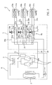
- a supercooling mechanism 60 which cools the refrigerant flowing to the cooling-side indoor heat exchangers from the heating-side indoor heat exchanger when a simultaneous cooling and heating operation is performed.
- the supercooling mechanism 60 is mounted at each of the branch liquid pipes 22a, 22b, and 22c: however, the supercooling mechanism 60 may be mounted at only a required branch liquid pipe(s) according to circumstances.
- the supercooling mechanism 60 is constructed such that heat exchange is performed between the refrigerant that is extracted from the liquid pipe header 25 and expanded into low temperature and low pressure and the refrigerant passing through the branch liquid pipes 22a, 22b, and 22c. As shown in FIG.
- the supercooling mechanism 60 comprises: supercooling pipes 61, 61a, 61b, and 61c connected to the inlet-side low-pressure pipe 21 from the liquid pipe header 25; a supercooling expansion valve 65 mounted on the supercooling pipes 61, 61a, 61b, and 61c for expanding the refrigerant; and supercooling heat exchangers 71a, 71b, and 71c for performing heat exchange between the supercooling pipes 61a, 61b, and 61c and the branch liquid pipes 22a, 22b, and 22c, respectively.
- the supercooling pipes 61, 61a, 61b, and 61c include: a main supercooling pipe 61 connected to the liquid pipe header 25; and branch supercooling pipes 61a, 61b, and 61c branched to the supercooling heat exchangers 71a, 71b, and 71c and connected to the low-pressure pipe 21.
- the supercooling expansion valve 65 is mounted on the main supercooling pipe 61.
- the supercooling expansion valve 65 of the present embodiment is an electronic expansion valve, which is opened when the simultaneous cooling and heating operation is performed.
- the skilled person will appreciate that other arrangements and types of valve are possible.
- the supercooling heat exchangers 71a, 71b, and 71c are mounted at the branch liquid pipes 22a, 22b, and 22c, respectively.
- the supercooling heat exchangers 71a, 71b, and 71c is constructed in a pipe-in-pipe structure in which the branch liquid pipes 22a, 22b, and 22c or the branch supercooling pipes 61a, 61b, and 61c are partially disposed in the branch supercooling pipes 61a, 61b, and 61c or the branch liquid pipes 22a, 22b, and 22c, respectively.
- the branch supercooling pipes 61a, 61b, and 61c are disposed in the enlarged portions of the branch liquid pipes 22a, 22b, and 22c, respectively.
- the supercooling heat exchangers 71a, 71b, and 71c may be constructed in various structures so long as the supercooling heat exchangers 71a, 71b, and 71c perform heat exchange between the branch liquid pipes 22a, 22b, and 22c and the branch supercooling pipes 61a, 61b, and 61c.
- refrigerant discharged from the compressor 1 flows to the liquid pipe 22 through the outdoor heat exchanger 2.
- the refrigerant flows to the high-pressure pipe 20.
- the refrigerant passing through the outdoor heat exchanger 2 flows through the liquid pipe header 25, the electronic expansion valves 55a and 55b, and the indoor heat exchangers 50a and 50b to cool the rooms where the corresponding indoor units are installed.
- the refrigerant flows to the compressor 1 through the low-pressure valves 31a and 31b, the low-pressure pipes 21a, 21b, and 21, and the accumulator 8.
- the refrigerant passing through the high-pressure pipe 20 flows through the high-pressure valve 30c, which is opened, and the indoor heat exchanger 50c to heat the room where the corresponding indoor unit is installed. Subsequently, the refrigerant passing through the indoor heat exchanger 50c flows to the liquid pipe header 25, at which refrigerant passing through the indoor heat exchanger 50c joins the refrigerant flowing to the indoor heat exchangers 50a and 50b, and then flows through the indoor heat exchangers 50a and 50b to assist the cooling of the rooms.
- the liquid refrigerant flowing to the branch liquid pipe 22c from the heating-side indoor heat exchanger 50c is supercooled by the supercooling mechanism 60, and the supercooled liquid refrigerant flows to the cooling-side indoor heat exchangers 50a and 50b.
- the supercooling expansion valve 65 When the supercooling expansion valve 65 is opened while the simultaneous cooling and heating operation, i.e., the main heating operation or the main cooling operation, is performed, some of the liquid refrigerant passing through the liquid pipe header 25 flows through the supercooling pipe 61. As a result, the liquid refrigerant is expanded, and therefore, the temperature and the pressure of the liquid refrigerant are lowered.
- the expanded refrigerant i.e., the low-temperature and low-pressure refrigerant, passes through the supercooling heat exchangers 71a, 71b, and 71c, at which heat exchange between the low-temperature and low-pressure refrigerant and the refrigerant flowing through the branch liquid pipes 22a, 22b, and 22c is performed. In this way, the supercooling operation is performed.
- the liquid refrigerant flowing through the heating-side indoor heat exchanger 50c is primarily supercooled by the low-temperature liquid refrigerant while passing through the supercooling heat exchanger 71c, and is then introduced into the liquid pipe header 25. Subsequently, the liquid refrigerant passes through the supercooling heat exchangers 71a and 71b. As a result, the liquid refrigerant is secondarily supercooled by the supercooling heat exchangers 71a and 71b, and is then introduced into the cooling-side indoor heat exchangers 50a and 50b.
- the refrigerant directly introduced into the cooling-side indoor heat exchangers 50a and 50b from the outdoor heat exchanger 2 through the liquid pipe header 25 also passes through the supercooling heat exchangers 71a and 71b.
- the liquid refrigerant is supercooled by the supercooling heat exchangers 71a and 71b, and therefore, more stable supply of the supercooled liquid refrigerant is accomplished.
- the liquid refrigerant discharged from the heating-side indoor heat exchanger is supercooled by the supercooling heat exchangers, and is then introduced into the cooling-side indoor heat exchangers. Consequently, embodiments of the present invention can have the effect of reducing noise generated from the cooling-side heat exchangers during the simultaneous cooling and heating operation and improving cooling capacity of the multi air conditioner.
Landscapes
- Engineering & Computer Science (AREA)
- Mechanical Engineering (AREA)
- General Engineering & Computer Science (AREA)
- Physics & Mathematics (AREA)
- Thermal Sciences (AREA)
- Chemical & Material Sciences (AREA)
- Combustion & Propulsion (AREA)
- Compression-Type Refrigeration Machines With Reversible Cycles (AREA)
Priority Applications (1)
| Application Number | Priority Date | Filing Date | Title |
|---|---|---|---|
| EP10182081A EP2306123A1 (de) | 2004-12-28 | 2005-12-02 | Unterkühler einer Mehrzonenklimaanlage |
Applications Claiming Priority (1)
| Application Number | Priority Date | Filing Date | Title |
|---|---|---|---|
| KR1020040113568A KR100733295B1 (ko) | 2004-12-28 | 2004-12-28 | 냉난방 동시형 멀티 에어컨의 과냉 장치 |
Publications (2)
| Publication Number | Publication Date |
|---|---|
| EP1686331A2 true EP1686331A2 (de) | 2006-08-02 |
| EP1686331A3 EP1686331A3 (de) | 2009-01-14 |
Family
ID=36118286
Family Applications (2)
| Application Number | Title | Priority Date | Filing Date |
|---|---|---|---|
| EP10182081A Withdrawn EP2306123A1 (de) | 2004-12-28 | 2005-12-02 | Unterkühler einer Mehrzonenklimaanlage |
| EP05257451A Ceased EP1686331A3 (de) | 2004-12-28 | 2005-12-02 | Unterkühler einer Mehrzonenklimaanlage |
Family Applications Before (1)
| Application Number | Title | Priority Date | Filing Date |
|---|---|---|---|
| EP10182081A Withdrawn EP2306123A1 (de) | 2004-12-28 | 2005-12-02 | Unterkühler einer Mehrzonenklimaanlage |
Country Status (4)
| Country | Link |
|---|---|
| US (1) | US7805961B2 (de) |
| EP (2) | EP2306123A1 (de) |
| KR (1) | KR100733295B1 (de) |
| CN (1) | CN100419350C (de) |
Cited By (4)
| Publication number | Priority date | Publication date | Assignee | Title |
|---|---|---|---|---|
| EP1921400A3 (de) * | 2006-10-19 | 2015-06-03 | LG Electronics, Inc. | Mehrfunktionsklimaanlage zum Heizen und Kühlen |
| EP2472200A4 (de) * | 2009-10-27 | 2015-10-21 | Mitsubishi Electric Corp | Klimaanlage |
| EP2128535A4 (de) * | 2007-01-23 | 2017-01-25 | Daikin Industries, Ltd. | Klimaanlage |
| EP3091314A4 (de) * | 2013-12-11 | 2017-11-01 | Daikin Industries, Ltd. | Kanalumschaltungssatzeinheit und kanalumschaltungssatzeinheitherstellungsverfahren |
Families Citing this family (17)
| Publication number | Priority date | Publication date | Assignee | Title |
|---|---|---|---|---|
| KR101218862B1 (ko) * | 2006-07-25 | 2013-01-08 | 엘지전자 주식회사 | 냉난방 동시형 멀티 공기 조화기 |
| KR101282565B1 (ko) * | 2006-07-29 | 2013-07-04 | 엘지전자 주식회사 | 냉난방 동시형 멀티 공기 조화기 |
| WO2009133644A1 (ja) * | 2008-04-30 | 2009-11-05 | 三菱電機株式会社 | 空気調和装置 |
| MX2010013181A (es) * | 2008-06-04 | 2010-12-21 | Danfoss As | Ensamble de valvula con colector integrado. |
| CN101608845B (zh) * | 2009-07-20 | 2011-11-30 | 西安建筑科技大学 | 并联式模块化热泵机组 |
| WO2011030418A1 (ja) * | 2009-09-10 | 2011-03-17 | 三菱電機株式会社 | 空気調和装置 |
| WO2012066608A1 (ja) * | 2010-11-19 | 2012-05-24 | 三菱電機株式会社 | 空気調和機 |
| KR101910658B1 (ko) * | 2011-07-18 | 2018-10-23 | 삼성전자주식회사 | 멀티형 공기조화기 |
| JP5932971B2 (ja) * | 2012-03-30 | 2016-06-08 | 三菱電機株式会社 | 冷凍装置及び冷凍サイクル装置 |
| CN103388922B (zh) * | 2013-07-31 | 2015-05-27 | 哈尔滨工业大学 | 一种双压缩机多功能空气源热泵空调系统 |
| JP5935836B2 (ja) * | 2014-07-02 | 2016-06-15 | ダイキン工業株式会社 | 空気調和装置 |
| KR101726073B1 (ko) * | 2015-10-01 | 2017-04-11 | 엘지전자 주식회사 | 공기조화 시스템 |
| JP6805759B2 (ja) * | 2016-11-29 | 2020-12-23 | 富士電機株式会社 | 冷媒回路装置 |
| WO2020121411A1 (ja) * | 2018-12-11 | 2020-06-18 | 三菱電機株式会社 | 空気調和装置 |
| JP6644194B1 (ja) * | 2019-01-21 | 2020-02-12 | 三菱電機株式会社 | 室外機及び空気調和装置 |
| CN113048584B (zh) * | 2021-01-20 | 2022-12-23 | 广东美的暖通设备有限公司 | 转轮调湿装置及具有其的空调系统及控制方法和控制器 |
| CN113154570A (zh) * | 2021-05-27 | 2021-07-23 | 广东积微科技有限公司 | 一种三管制多功能多联机系统及其控制方法 |
Citations (1)
| Publication number | Priority date | Publication date | Assignee | Title |
|---|---|---|---|---|
| EP0496505A2 (de) | 1991-01-10 | 1992-07-29 | Mitsubishi Denki Kabushiki Kaisha | Klimaanlage |
Family Cites Families (24)
| Publication number | Priority date | Publication date | Assignee | Title |
|---|---|---|---|---|
| US243759A (en) * | 1881-07-05 | Refrigerating apparatus by means of ammonia and other substances | ||
| US4285205A (en) * | 1979-12-20 | 1981-08-25 | Martin Leonard I | Refrigerant sub-cooling |
| US4760707A (en) * | 1985-09-26 | 1988-08-02 | Carrier Corporation | Thermo-charger for multiplex air conditioning system |
| KR920008504B1 (ko) * | 1988-10-17 | 1992-09-30 | 미쓰비시전기주식회사 | 공기조화장치 |
| JP3289366B2 (ja) * | 1993-03-08 | 2002-06-04 | ダイキン工業株式会社 | 冷凍装置 |
| JP3729552B2 (ja) * | 1996-02-22 | 2005-12-21 | 東プレ株式会社 | 空気調和装置 |
| US5987916A (en) * | 1997-09-19 | 1999-11-23 | Egbert; Mark | System for supermarket refrigeration having reduced refrigerant charge |
| JP2000304374A (ja) * | 1999-04-22 | 2000-11-02 | Yanmar Diesel Engine Co Ltd | エンジンヒートポンプ |
| DE60037445T2 (de) * | 1999-10-18 | 2008-12-04 | Daikin Industries, Ltd. | Kältevorrichtung |
| JP2002013763A (ja) | 2000-04-24 | 2002-01-18 | Daikin Ind Ltd | 空気調和機の分岐ユニット |
| US20050016209A1 (en) * | 2002-02-27 | 2005-01-27 | Huelle Zbigniew Ryszard | Coolant distributor |
| AU2003213443B2 (en) | 2002-03-18 | 2005-05-05 | Daikin Industries, Ltd. | Pressure control device of air conditioner and air conditioner having the device |
| KR100437803B1 (ko) * | 2002-06-12 | 2004-06-30 | 엘지전자 주식회사 | 냉난방 동시형 멀티공기조화기 및 그 제어방법 |
| US7493775B2 (en) * | 2002-10-30 | 2009-02-24 | Mitsubishi Denki Kabushiki Kaisha | Air conditioner |
| KR100463548B1 (ko) * | 2003-01-13 | 2004-12-29 | 엘지전자 주식회사 | 공기조화기용 제상장치 |
| KR100504498B1 (ko) * | 2003-01-13 | 2005-08-03 | 엘지전자 주식회사 | 공기조화기용 과냉확보장치 |
| KR100504509B1 (ko) * | 2003-01-16 | 2005-08-03 | 엘지전자 주식회사 | 차단 가능한 다중 분배기를 갖는 냉난방 동시형멀티공기조화기 |
| KR100504880B1 (ko) * | 2003-04-12 | 2005-07-29 | 엘지전자 주식회사 | 과냉어큐뮬레이터를 구비한 냉난방 동시형 멀티 에어컨 |
| KR20040090131A (ko) * | 2003-04-16 | 2004-10-22 | 엘지전자 주식회사 | 멀티 에어컨 시스템의 과냉각용 열교환 장치 |
| JP4348113B2 (ja) * | 2003-05-23 | 2009-10-21 | 株式会社ヴァレオサーマルシステムズ | 熱交換器 |
| KR100658461B1 (ko) * | 2003-10-06 | 2006-12-15 | 다이킨 고교 가부시키가이샤 | 냉동장치 |
| US7406839B2 (en) * | 2005-10-05 | 2008-08-05 | American Power Conversion Corporation | Sub-cooling unit for cooling system and method |
| JP4254863B2 (ja) * | 2007-01-23 | 2009-04-15 | ダイキン工業株式会社 | 空気調和装置 |
| KR200488827Y1 (ko) * | 2017-09-07 | 2019-03-25 | 두산중공업 주식회사 | 알곤 가스 퍼지 및 어스용 지그 |
-
2004
- 2004-12-28 KR KR1020040113568A patent/KR100733295B1/ko not_active Expired - Fee Related
-
2005
- 2005-11-28 US US11/287,391 patent/US7805961B2/en not_active Expired - Fee Related
- 2005-12-02 EP EP10182081A patent/EP2306123A1/de not_active Withdrawn
- 2005-12-02 EP EP05257451A patent/EP1686331A3/de not_active Ceased
- 2005-12-14 CN CNB2005101295896A patent/CN100419350C/zh not_active Expired - Fee Related
Patent Citations (1)
| Publication number | Priority date | Publication date | Assignee | Title |
|---|---|---|---|---|
| EP0496505A2 (de) | 1991-01-10 | 1992-07-29 | Mitsubishi Denki Kabushiki Kaisha | Klimaanlage |
Cited By (4)
| Publication number | Priority date | Publication date | Assignee | Title |
|---|---|---|---|---|
| EP1921400A3 (de) * | 2006-10-19 | 2015-06-03 | LG Electronics, Inc. | Mehrfunktionsklimaanlage zum Heizen und Kühlen |
| EP2128535A4 (de) * | 2007-01-23 | 2017-01-25 | Daikin Industries, Ltd. | Klimaanlage |
| EP2472200A4 (de) * | 2009-10-27 | 2015-10-21 | Mitsubishi Electric Corp | Klimaanlage |
| EP3091314A4 (de) * | 2013-12-11 | 2017-11-01 | Daikin Industries, Ltd. | Kanalumschaltungssatzeinheit und kanalumschaltungssatzeinheitherstellungsverfahren |
Also Published As
| Publication number | Publication date |
|---|---|
| EP1686331A3 (de) | 2009-01-14 |
| CN100419350C (zh) | 2008-09-17 |
| EP2306123A1 (de) | 2011-04-06 |
| KR100733295B1 (ko) | 2007-06-28 |
| US20060137381A1 (en) | 2006-06-29 |
| US7805961B2 (en) | 2010-10-05 |
| KR20060075021A (ko) | 2006-07-04 |
| CN1796905A (zh) | 2006-07-05 |
Similar Documents
| Publication | Publication Date | Title |
|---|---|---|
| EP2306123A1 (de) | Unterkühler einer Mehrzonenklimaanlage | |
| KR100463548B1 (ko) | 공기조화기용 제상장치 | |
| EP3450881B1 (de) | Klimaanlage | |
| EP2339268B1 (de) | Wärmepumpenvorrichtung | |
| JP4997004B2 (ja) | 空気調和装置 | |
| JP5625691B2 (ja) | 冷凍装置 | |
| EP1555494A2 (de) | Heiz- und kühlsystem | |
| KR101706865B1 (ko) | 공기조화기 | |
| KR100499507B1 (ko) | 멀티공기조화기 | |
| EP1610076A2 (de) | Kälteanlage und Verfahren zum Betrieb derselben | |
| EP2541170A1 (de) | Heisswasserversorgungssystem für eine klimaanlage | |
| JP2010014351A (ja) | 冷凍空調装置 | |
| JP5186398B2 (ja) | 空気調和機 | |
| JP3511161B2 (ja) | 空気調和装置 | |
| KR100504499B1 (ko) | 냉난방 동시형 멀티공기조화기용 응축액 제거장치 | |
| CN100541053C (zh) | 制冷/制热系统及其控制方法 | |
| JPH0894205A (ja) | 空気調和装置 | |
| KR20080075581A (ko) | 공기조화 시스템 및 그 제어방법 | |
| KR100463549B1 (ko) | 냉난방 동시형 멀티공기조화기용 응축액 제거장치 | |
| KR100469288B1 (ko) | 냉난방 동시형 멀티공기조화기용 응축액 제거장치 | |
| JPH1194395A (ja) | 多室形空気調和装置 | |
| JP2009281595A (ja) | 冷凍装置 | |
| JPH11211258A (ja) | 多室形空気調和装置 | |
| JP2005221167A (ja) | 空気調和装置 | |
| WO2024252472A1 (ja) | 冷凍サイクル装置 |
Legal Events
| Date | Code | Title | Description |
|---|---|---|---|
| PUAI | Public reference made under article 153(3) epc to a published international application that has entered the european phase |
Free format text: ORIGINAL CODE: 0009012 |
|
| 17P | Request for examination filed |
Effective date: 20051222 |
|
| AK | Designated contracting states |
Kind code of ref document: A2 Designated state(s): AT BE BG CH CY CZ DE DK EE ES FI FR GB GR HU IE IS IT LI LT LU LV MC NL PL PT RO SE SI SK TR |
|
| AX | Request for extension of the european patent |
Extension state: AL BA HR MK YU |
|
| PUAL | Search report despatched |
Free format text: ORIGINAL CODE: 0009013 |
|
| AK | Designated contracting states |
Kind code of ref document: A3 Designated state(s): AT BE BG CH CY CZ DE DK EE ES FI FR GB GR HU IE IS IT LI LT LU LV MC NL PL PT RO SE SI SK TR |
|
| AX | Request for extension of the european patent |
Extension state: AL BA HR MK YU |
|
| 17Q | First examination report despatched |
Effective date: 20090424 |
|
| AKX | Designation fees paid |
Designated state(s): DE FR GB IT |
|
| STAA | Information on the status of an ep patent application or granted ep patent |
Free format text: STATUS: THE APPLICATION HAS BEEN REFUSED |
|
| 18R | Application refused |
Effective date: 20110819 |