EP1688112B1 - Applikator für Tampon für die weibliche Hygiene und Frauenhygieneartikel - Google Patents
Applikator für Tampon für die weibliche Hygiene und Frauenhygieneartikel Download PDFInfo
- Publication number
- EP1688112B1 EP1688112B1 EP05258111A EP05258111A EP1688112B1 EP 1688112 B1 EP1688112 B1 EP 1688112B1 EP 05258111 A EP05258111 A EP 05258111A EP 05258111 A EP05258111 A EP 05258111A EP 1688112 B1 EP1688112 B1 EP 1688112B1
- Authority
- EP
- European Patent Office
- Prior art keywords
- push rod
- tampon
- casing
- flange
- tip end
- Prior art date
- Legal status (The legal status is an assumption and is not a legal conclusion. Google has not performed a legal analysis and makes no representation as to the accuracy of the status listed.)
- Expired - Lifetime
Links
Images


Classifications
-
- A—HUMAN NECESSITIES
- A61—MEDICAL OR VETERINARY SCIENCE; HYGIENE
- A61F—FILTERS IMPLANTABLE INTO BLOOD VESSELS; PROSTHESES; DEVICES PROVIDING PATENCY TO, OR PREVENTING COLLAPSING OF, TUBULAR STRUCTURES OF THE BODY, e.g. STENTS; ORTHOPAEDIC, NURSING OR CONTRACEPTIVE DEVICES; FOMENTATION; TREATMENT OR PROTECTION OF EYES OR EARS; BANDAGES, DRESSINGS OR ABSORBENT PADS; FIRST-AID KITS
- A61F13/00—Bandages or dressings; Absorbent pads
- A61F13/15—Absorbent pads, e.g. sanitary towels, swabs or tampons for external or internal application to the body; Supporting or fastening means therefor; Tampon applicators
- A61F13/20—Tampons, e.g. catamenial tampons; Accessories therefor
- A61F13/26—Means for inserting tampons, i.e. applicators
-
- C—CHEMISTRY; METALLURGY
- C25—ELECTROLYTIC OR ELECTROPHORETIC PROCESSES; APPARATUS THEREFOR
- C25D—PROCESSES FOR THE ELECTROLYTIC OR ELECTROPHORETIC PRODUCTION OF COATINGS; ELECTROFORMING; APPARATUS THEREFOR
- C25D5/00—Electroplating characterised by the process; Pretreatment or after-treatment of workpieces
- C25D5/02—Electroplating of selected surface areas
- C25D5/026—Electroplating of selected surface areas using locally applied jets of electrolyte
-
- C—CHEMISTRY; METALLURGY
- C25—ELECTROLYTIC OR ELECTROPHORETIC PROCESSES; APPARATUS THEREFOR
- C25D—PROCESSES FOR THE ELECTROLYTIC OR ELECTROPHORETIC PRODUCTION OF COATINGS; ELECTROFORMING; APPARATUS THEREFOR
- C25D17/00—Constructional parts, or assemblies thereof, of cells for electrolytic coating
- C25D17/02—Tanks; Installations therefor
- C25D17/04—External supporting frames or structures
-
- C—CHEMISTRY; METALLURGY
- C25—ELECTROLYTIC OR ELECTROPHORETIC PROCESSES; APPARATUS THEREFOR
- C25D—PROCESSES FOR THE ELECTROLYTIC OR ELECTROPHORETIC PRODUCTION OF COATINGS; ELECTROFORMING; APPARATUS THEREFOR
- C25D17/00—Constructional parts, or assemblies thereof, of cells for electrolytic coating
- C25D17/06—Suspending or supporting devices for articles to be coated
-
- C—CHEMISTRY; METALLURGY
- C25—ELECTROLYTIC OR ELECTROPHORETIC PROCESSES; APPARATUS THEREFOR
- C25D—PROCESSES FOR THE ELECTROLYTIC OR ELECTROPHORETIC PRODUCTION OF COATINGS; ELECTROFORMING; APPARATUS THEREFOR
- C25D21/00—Processes for servicing or operating cells for electrolytic coating
- C25D21/12—Process control or regulation
-
- A—HUMAN NECESSITIES
- A61—MEDICAL OR VETERINARY SCIENCE; HYGIENE
- A61F—FILTERS IMPLANTABLE INTO BLOOD VESSELS; PROSTHESES; DEVICES PROVIDING PATENCY TO, OR PREVENTING COLLAPSING OF, TUBULAR STRUCTURES OF THE BODY, e.g. STENTS; ORTHOPAEDIC, NURSING OR CONTRACEPTIVE DEVICES; FOMENTATION; TREATMENT OR PROTECTION OF EYES OR EARS; BANDAGES, DRESSINGS OR ABSORBENT PADS; FIRST-AID KITS
- A61F13/00—Bandages or dressings; Absorbent pads
- A61F13/15—Absorbent pads, e.g. sanitary towels, swabs or tampons for external or internal application to the body; Supporting or fastening means therefor; Tampon applicators
- A61F13/20—Tampons, e.g. catamenial tampons; Accessories therefor
- A61F13/26—Means for inserting tampons, i.e. applicators
- A61F13/266—Insertion devices, e.g. rods or plungers, separate from the tampon
Definitions
- the present invention relates to an applicator for use in inserting a feminine hygiene tampon (hereinafter also simply called a tampon) into a vagina, relates in particular to an applicator for a feminine hygiene tampon which can avoid a push rod of the applicator from remaining in the vagina, and relates in particular to a feminine-hygiene product having the applicator.
- a feminine hygiene tampon hereinafter also simply called a tampon
- a feminine-hygiene napkin and tampon are generally known.
- the feminine-hygiene tampon is an absorbing material which is inserted into a vagina to absorb and hold bodily fluids such as blood.
- feminine-hygiene tampons which are commercially available are accommodated in an applicator for use in inserting it into a vagina.
- the applicator for the feminine-hygiene tampon is formed with a casing which accommodates the tampon and a push rod which is disposed inside the casing and is used to push the tampon out of the casing tip end (see JP-A-61-249464 , Patent Reference 1).
- Fig. 12 is a cross section showing an applicator in Patent Reference 1.
- This applicator 100 has a petaloid tampon outlet 150 at the tip end of a casing 110.
- a push rod 120 which slides inside the casing 110 pushes an end part of a tampon 130.
- the tampon 130 is pushed out of the tampon outlet 150, and is inserted into a vagina.
- the push rod 120 pushes the tampon 130 out of the casing 110 to insert it into a vagina
- the push rod 120 is thrust too, causing the petals 150 of the casing 110 to sit at a tip end 170 of the push rod 120.
- the force that the petals 150 having opened return to the original state acts on the push rod 120, which triggers the push rod 120 to come out of the tip end 150 of the casing 110. Consequently, a problem sometimes arises that the push rod 120 remains inside the body (in the vagina) even though the casing 110 is taken out.
- a method may be mentioned in which after the push rod is set in the casing during assembly, the end part of the push rod that does not abut against the tampon is extended in diameter, and thus the push rod is prevented from entering the casing.
- a push rod with a flange may be mentioned (see JP-UM-A-1-072219 , Patent Reference 2).
- Fig. 13 is a cross section showing an applicator in Patent Reference 2.
- This applicator 101 has a flange (stopper) 161 near a tip end 171 of a push rod 121 that abuts against a tampon 131.
- US3765416 discloses an applicator comprising a casing which accommodates a tampon and a push rod which is disposed inside the casing to push the tampon out of the casing, wherein the push rod has a flange having a maximum diameter of the push rod at a predetermined distance from a tip end of the push rod abutting against the tampon, and an outer diameter of the push rod from the flange to the tip end is gradually reduced overall.
- the outer diameter of the push rod 121 is nearly uniform in the portion from the tip end 171 of the push rod 121 to the flange 161, and the outer diameter of the push rod 121, except the flange 161, is almost the same size.
- a structure is formed in which only the presence of the flange (stopper) 161 contributes to preventing the push rod 121 from coming out and the other parts do not serve to prevent coming out. Therefore, the effect of preventing the push rod from coming out can be obtained to some extent, but it is not perfect, making further improvement desirable.
- the present invention has been made in view of these problems.
- Objects of the invention are to provide an applicator for a feminine hygiene tampon which can reliably prevent a push rod of an applicator from coming out of a casing and remaining inside a vagina, and to provide a feminine hygiene product having the applicator.
- the present invention provides the following.
- an applicator for use in inserting a feminine hygiene tampon into a vagina, the applicator comprising: a casing which accommodates a tampon; and a push rod which is disposed inside the casing to push the tampon out of the casing, wherein the push rod has a flange having a maximum diameter of the push rod at a predetermined distance from a tip end of the push rod abutting against the tampon, and an outer diameter of the push rod from the flange to the tip end is reduced overall, characterised in that a portion of the push rod between the flange and the tip end is formed with at least one step.
- the flange is disposed midway of the push rod, and the outer diameter from the flange to the tip end is reduced overall.
- petals being the tampon outlet generally meaning the tip ends of the tampon outlet
- a force that returns the rod into the casing acts on the push rod. Therefore, a force that returns the push rod into the casing also acts on the portion from the tip end to the flange in addition to the flange. Accordingly, the push rod can more reliably be prevented from coming out.
- the diameter being reduced overall in the present invention, it is acceptable that the diameter be reduced overall in appearance, and it is not reduced in diameter continuously. More specifically, the part increased in diameter may partially include a flat part, a stepped part, a recess, etc.
- an applicator for use in inserting a feminine hygiene tampon into a vagina, the applicator comprising: a casing which accommodates a tampon; and a push rod which is disposed inside the casing to push the tampon out of the casing, wherein the push rod has a flange having a maximum diameter of the push rod at a predetermined distance from a tip end of the push rod abutting against the tampon, and an outer diameter of the push rod from the flange to the tip end is reduced overall, characterised in that a portion of the push rod between the flange and the tip end is formed with a recess and a projection.
- the petals forming the tampon outlet reach a wall formed by a step
- the petals are caught at the wall formed.
- a lift is generated that is perpendicular to the force of the petals acting on the top in the direction toward the inside the casing. Therefore, a force that returns the push rod into the casing acts on the push rod, and the push rod can be more reliably prevented from coming out.
- a drop causes vibrations which are transmitted to the petals. Accordingly, a user of the applicator is made aware that the rod is coming near the insertion limit by the vibrations, and the user can stop pushing the push rod as desired. Therefore, the push rod can be prevented from coming out of the casing.
- an applicator for a feminine hygiene tampon is a predetermined distance of 3 mm to 25 mm, inclusive, from the tip end.
- the distance from the tip end to the flange is 3 mm or more to allow the tip end of the push rod to be protruded out of the petals at the tip end of the casing, and the tampon can be inserted securely.
- it is 25 mm or less to secure a volume to accommodate the tampon in the casing.
- an applicator for a feminine hygiene tampon has a portion from the flange to the tip end which is formed with a stepped slope.
- the force of the petals acts obliquely on the slope. Therefore, a lift is generated that is perpendicular to the force of the petals acting on the slope in the direction toward the inside of the casing.
- a force that returns the push rod into the casing acts on the push rod, and the effect can be obtained that prevents the push rod from coming out.
- vibrations are transmitted to the petals. Accordingly, a user of the applicator is made aware that the rod is coming near the insertion limit by vibrations, and the user can stop pushing the push rod as desired. Therefore, the push rod can be prevented from coming out of the casing.
- a feminine hygiene product has an applicator for a feminine hygiene tampon according to any one of the first through fifth embodiment of the present invention, and a tampon.
- the feminine hygiene product of the fifth embodiment of the present invention has a tampon inside the casing of the applicator. According to the feminine hygiene product of the fourth embodiment of the present invention, it is unlikely that the push rod of the applicator will come out of the casing and remain in the vagina, and the tampon can be inserted into the vagina easily.
- the applicator for a feminine hygiene tampon can more reliably prevent the push rod of the applicator from coming out of the casing and remaining in the vagina, and the feminine hygiene product having the applicator can be provided.
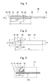
- Fig. 1 is a cross section of an applicator for a feminine-hygiene tampon of the first embodiment, which does not constitute an embodiment of the invention.
- This applicator 90 has a casing 10 which accommodates a tampon 30, and a push rod 20 which is disposed in the casing 10 to push the tampon 30 out of the casing 10.
- a tampon outlet 50 in a petaloid shape is disposed which is opened in pushing the tampon 30.
- a flange 60 is disposed on the tip end side thereof.
- a pull cord 40 is extended from the tampon 30.
- the inside of the push rod 20 is hollow.
- the pull cord 40 of the tampon 30 passes through the inside of the push rod 20, and the pull cord 40 is extended to the outside of the applicator from the end of the tampon 30 on the side where the push rod 20 does not abut.
- the individual components of the applicator 90 will be described.
- the casing 10 has a circular cross section, and a hollow is formed inside to accommodate the tampon 30.
- the tampon outlet 50 in a petaloid shape is formed which is opened in pushing the tampon 30.
- an opening through which the push rod 20 penetrates is disposed.
- the diameter of the casing 10 (L9 in Fig. 1 ) generally ranges from 10 mm to 25 mm. Since the tampon to be an absorbing material is accommodated in the casing, an absorbing amount of the tampon accommodated in the casing cannot be secured sufficiently when the diameter is less than 10 mm. Moreover, when the diameter is more than 25 mm, it is not preferable because a user is likely to experience discomfort when inserting the applicator into the vagina or during the use of the tampon.
- the casing 10 can be fabricated by injection molding with a thermoplastic such as polyethylene resin.
- a thermoplastic such as polyethylene resin.
- materials having flexibility are preferably used for the purpose of providing a bendable function to the petals (slits) which form the tampon outlet 50.
- polyethylene resins can be used preferably.
- mica, titanium oxide, pigments, etc. may be added appropriately.
- the shape of the casing is not particularly limited. In order to reduce user discomfort when inserting the applicator into the body as much as possible, it is preferably nearly a cylindrical shape. Moreover, the shape of the opening to be the tampon outlet is also not particularly limited. In order to open bendably, to prevent a tampon from coming out accidentally, and to smoothly insert a tampon into a vagina in pushing the tampon, the petaloid (radial) slit shape is preferable.
- Fig. 2 is an enlarged view of the push rod 20 shown in Fig. 1 .
- the push rod 20 has a slim cylindrical shape, and has a hollow therein to penetrate through the pull cord 40 of the tampon 30.
- the push rod 20 has a cylindrical base part 20a, a flange 60 which stands vertically from the base part 20a and has the maximum diameter of the push rod 20, and a beveled part 80 by which the diameter of the push rod 20 is gradually reduced from the flange 60 toward a tip end 70.
- the length of the push rod 20 in the longitudinal direction (L5 in Fig. 2 ) is nearly equal to the length of the casing in the longitudinal direction (L7 in Fig. 1 ) so that the tampon can be pushed into the vagina sufficiently.
- Z L5 - L7
- Z desirably ranges from above -2 mm to below 2 mm (-2 mm ⁇ Z ⁇ 2 mm).
- the flange 60 is a portion that is the maximum diameter of the push rod, and that serves to prevent the push rod from coming out of the tampon outlet in pushing the tampon out of the tampon outlet of the casing, and that also serves as a stopper to prevent the push rod from coming off the opposite end of the tampon outlet.
- the length of the push rod 20 of the flange 60 in the longitudinal direction (L10 in Fig. 2 ) requires the strength to the extent that the push rod 20 does not come out or come off the casing 10, it is preferably 1 mm or more.
- the diameter of the flange 60 (L1 in Fig. 2 ), to be the maximum diameter of the push rod 20, is preferably almost the same diameter as that of the casing in order to prevent the push rod from coming off the opposite end of the tampon outlet of the casing.
- the difference between it and the diameter of the casing is preferably about 2 mm in general.
- the diameter of the casing (L9 in Fig. 1 ) is set to range from 10 mm to 25 mm
- the diameter of the flange of the push rod (L1 in Fig. 2 ) preferably ranges from 8 mm to 23 mm, corresponding to the casing.
- the diameter of the base part 20a of the push rod (L3 in Fig. 2 ) preferably ranges from 4 mm to 20 mm.
- the tip end 70 on the side abutting against the tampon 30 has an outer diameter smaller than the outer diameter of the flange 60.
- the diameter of the tip end of the push rod 70 (L2 in Fig. 2 ) for use in the present invention preferably ranges from 4 mm to 23 mm. When the diameter of the tip end is less than 4 mm, this is not preferable because the inside of the vagina might be injured in the case in which the tip end contacts the inside of the vagina.
- the portion from the tip end 70 of the push rod 20 to the flange 60 has the beveled part 80 by which the diameter of the push rod 20 is gradually increased.
- the length from the tip end 70 to the flange 60 in the longitudinal direction (L4 in Fig. 2 ) being "a predetermined distance" in the push rod 20 is preferably 3 mm to 25 mm, inclusive.
- the length of the vagina is 80 to 100 mm. Since the portion with sphincters that feels discomfort extends about 40 to 50 mm from the vaginal opening, in consideration of these circumstances, the length of a tampon (L6 in Fig. 1 ) is preferably about 30 mm to 50 mm.
- the length from the tip end of the push rod to the flange in the longitudinal direction (L4 in Fig. 2 ) can be selected in accordance with the size of a tampon, for example, when the length of the tampon (L6 in Fig. 1 ) is 30 mm at minimum, the length from the tip end of the push rod to the flange in the longitudinal direction (L4 in Fig. 2 ) preferably ranges from 3 to 20 mm.
- a beveled angle of the push rod 20 in the longitudinal direction (8 in Fig. 2 ) ranges from an angle of 3 degrees to 70 degrees, inclusive.
- the beveled angle preferably ranges from an angle of 3 degrees to 5 degrees.
- the beveled angle is an angle of about 70 degrees.
- Fig. 3 is a partially enlarged cross section of a modification of the push rod (corresponding to the area surrounded by the dotted line in Fig. 2 ).
- a push rod 21 of the modification has a cylindrical base part 21a, a flange 61 which stands vertically from the base part 21a and has the maximum diameter of the push rod 21, and a beveled part 81 by which the diameter of the push rod 21 is gradually reduced from the flange 61 toward a tip end 71.
- the beveled part 81 is different from that in Fig. 2 in that the beveled angle has a curved surface, not a constant slope.
- the beveled part may be a curved surface with a recess, or may be a curved surface with a projection.
- the push rod may be of the same material as that of the casing, or may be of a different material.
- a thermoplastic such as polyethylene resin is used for fabrication by injection molding. Since forth pushes a tampon out of the casing to insert it into the body, a hard material such as polypropylene and polyester resin can be used.
- a hard material such as polypropylene and polyester resin can be used.
- mica, titanium oxide, pigments, etc. can be added as appropriate.
- the other end (rear end) projected outside the applicator is pressed, and the push rod slides inside the casing to push the tampon that is accommodated inside the casing out of the tampon outlet of the casing. Therefore, the shape is not particularly limited as long as these functions are satisfied. Furthermore, the inside may or may not be hollow, but hollow is preferable because the pull cord of the tampon can penetrate therethrough.
- the shape of the tampon 30 is not particularly restricted as long as it can be accommodated in the casing, but it is preferably a nearly cylindrical shape for the purpose of reducing discomfort as much as possible when a user uses the tampon.
- the length of the vagina is 80 to 100 mm. Since the portion with sphincters that fells discomfort extends about 40 to 50 mm from the vagina opening, in consideration of these circumstances, the length of a tampon (L6 in Fig. 1 ) is preferably about 30 mm to 50 mm.
- the material of the tampon 30 is not particularly restricted as long as the material can be formed an absorbing material to absorb and hold bodily fluids. For example, it can form a lump of fibers mainly formed of rayon and cotton having water absorbing properties. Furthermore, in order to prevent fibers from coming off and to reduce discomfort when a user uses a tampon, a surfacing material can be used on the surface of a tampon.
- span lacing nonwoven fabric formation by high-pressure water flow entangling
- thermal embossing thermal embossing
- perforated films and perforated nets having materials of polyethylene resins for use in the present invention, for example, such a tampon is mentioned in which a lump of fibers mainly formed of rayon and cotton having water absorbing properties is covered with a nonwoven fabric having polyester fibers on the surface thereof by spanbonding, and a pull cord is provided.
- the pull cord 40 is a cord for use in pulling the tampon out of the body.
- the material of the pull cord it is not particularly limited as long as it has the strength so that the tampon can be pulled out.
- cotton yarn, and intertwined yarn of cotton yarn and polyester yarn can be mentioned.
- the following method may be mentioned: cotton yarn as the pull cord is sewn to the tampon having a lump of fibers wrapped with a surfacing material by a sewing machine.
- a lump of fibers wrapped with a surfacing material is perforated, the pull cord passes through the hole, and then the end part of the cord is tied.
- the end part of the pull cord is tied to form a loop, a lump of wide fibers passes through the loop, and then the lump of fibers is folded to wind the cord.
- the petals 55 which form the tampon outlet 50 of the casing 10 of the applicator are opened along the outer diameter of the casing 10 before thermoforming.
- the petals 55 are thermoformed, rounded and then closed. Therefore, the push rod 20 is first inserted into the casing 10 from the opening which forms the tampon outlet 50 before thermoforming, from the rear end without the flange 60.
- the tampon 30 is inserted into the casing 10 as the pull cord 40 penetrates through a hollow inside the push rod 20.
- the petals 55 of the tampon outlet 50 are formed round by thermoforming, and the push rod 20 and the tampon 30 are put inside the casing 10. In this manner, the applicator can be fabricated.
- the operation of the applicator of the first example will be described.
- the rear end of the push rod is pushed in the initial state in Fig. 1 , and then the push rod 20 slides inside the casing 10.
- the tip end 70 of the push rod 20 abuts against the tampon 30 that is accommodated inside the casing 10.
- the tip end 70 of the push rod 20 pushes the tampon 30 to open the petals 55 of the tampon outlet 50 of the casing 10, and the tampon 30 is pushed out of the tampon outlet 50.
- the tip end of the push rod 20 is protruded through the tampon outlet 50, and the tip ends of the petals 55 are sit at near the tip end of the push rod 20 (the state shown in Fig. 3 ).
- the portion from the tip end 171 to the flange 161 is flat with no bevel.
- the force from the tip ends of the petals 155 of the casing act in the direction of F1 which is perpendicular to a plane P corresponding to that portion of the push rod (corresponding to the flat part).
- a drag is generated against the force F1 in the plane P of the portion from the tip end of the push rod to the flange.
- this drag acts perpendicular to the plane P in the direction opposite to a force F2 and is then cancelled, the push rod is not affected in the lateral direction.
- the push rods 20 and 21 have the beveled parts 80 and 81, respectively, from the tip end to the flange.
- a plane P in the beveled part of the push rod corresponding to the beveled parts 80 and 81
- a plane P in the beveled part of the push rod has a bevel. Therefore, when the petals 55 forming the tampon outlet (the tampon outlet 50 in Fig.
- the push rod for use in the present invention is formed to have the outer diameter of the tip end smaller than the outer diameter of the flange, and the outer diameter from the tip end to the flange is gradually increased overall. More specifically, the portion from the tip end to the flange has irregularities with a step, etc. Furthermore, when a step is provided, not only a single step but also multiple steps may be provided, or bumps and dips may be formed.
- Fig. 6 is a partially enlarged cross section of a push rod of a first embodiment according to the present invention (corresponding to the area surrounded by a dotted line in Fig. 2 ).
- a push rod 22 shown in Fig. 6 has a cylindrical base part 22a, a flange 62 which stands perpendicularly from the base part 22a and has the maximum diameter of the push rod 22, and a slope D, a step B, and a slope C are sequentially formed in stepped fashion from the flange 62 to a tip end 72.
- the diameter of the push rod 22 is gradually reduced overall toward the tip end 72.
- the advantages below are further provided. More specifically, even though the petals 55 step over the first slope C, the step B causes vibrations, 'clicks,' to a user. Thus, the user is likely to recognize that that point is the insertion limit, and the user will not put the push rod further. Even if the push rod is further pushed, the presence of the second slope D and the wall of the flange 62 prevent the push rod from being pushed hard as the rod extends over them. Therefore, the push rod can be effectively prevented from coming off the casing and remaining in the body.
- Fig. 7 is a partially enlarged cross section of a push rod of a second embodiment according to the present invention (corresponding to the area surrounded by a dotted line in Fig. 2 ).
- a push rod 23 shown in Fig. 7 has a cylindrical base part 23a, a flange 63 which stands perpendicularly from the base part 23a and has the maximum diameter of the push rod 23, and a flat part E and a step F are continuously formed from the flange 63 toward a tip end 73.
- the diameter of the push rod 23 is reduced toward the tip end 73 step by step.
- a bevel angel corresponding to ⁇ in Figs. 2 and 5 is ⁇ 1.
- the length from the tip end 73 to the flange 63 in the longitudinal direction being "a predetermined distance" is L4
- a force from petals 55 of a tampon outlet 50 acts as a force F1 against the plane of the portion from the tip end of the push rod to the flange as similar to Fig. 4 .
- the force F1 acts only vertically to the plane P in the direction of a force F2
- the push rod is not affected in the lateral direction in the planes P1, P2, and P3.
- a push rod 24 shown in Fig. 10 has a cylindrical base part 24a, a flange 64 which stands perpendicularly from the base part 24a and has the maximum diameter of the push rod 24, and a beveled part E' and a step F' are continuously formed from the flange 64 toward tip end 74.
- the diameter of the push rod 24 is reduced toward the tip end 74 step by step. More specifically, it is different from that shown in Fig. 7 in that the flat part of the step shown in Fig. 7 is a slope. As described above, the rod may have a sloping step.
- Fig. 11 is a partially enlarged cross section of a push rod of a third embodiments of the invention (corresponding to the area surrounded by a dotted line in Fig. 2 ).
- a push rod 25 shown in Fig. 11 has a cylindrical base part 25a, a flange 65 which stands perpendicularly from the base part 25a and has the maximum diameter of the push rod 25, and a projection J which is next to the flange 65 and lower than the flange 65.
- the rod has recesses and projections overall while the diameter thereof is gradually reduced toward a tip end 75.
- a beveled angle corresponding to ⁇ in Figs. 2 and 5 is ⁇ 2.
- the wall is designed to gradually increase in height from the push rod tip end side, the rod is caught at the projection J in the state in which the petals 55 open slightly, and the rod drops in the recess even though the petals 55 pass over the projection J Consequently, the petals 55 of the casing will not pass over the flange 65 of the push rod, and thus the push rod can be prevented from coming out of the casing and remaining in the body.
Landscapes
- Chemical & Material Sciences (AREA)
- Engineering & Computer Science (AREA)
- Health & Medical Sciences (AREA)
- Chemical Kinetics & Catalysis (AREA)
- Electrochemistry (AREA)
- Materials Engineering (AREA)
- Metallurgy (AREA)
- Organic Chemistry (AREA)
- Epidemiology (AREA)
- Biomedical Technology (AREA)
- Heart & Thoracic Surgery (AREA)
- Vascular Medicine (AREA)
- Life Sciences & Earth Sciences (AREA)
- Animal Behavior & Ethology (AREA)
- General Health & Medical Sciences (AREA)
- Public Health (AREA)
- Veterinary Medicine (AREA)
- Automation & Control Theory (AREA)
- Absorbent Articles And Supports Therefor (AREA)
Claims (6)
- Applikator zum Einführen eines Frauenhygiene-Tampons in die Vagina, umfassend:ein Gehäuse (10) zur Aufnahme des Tampons; undeine im Gehäuse angeordnete Schubstange (20) zum Herausschieben des Tampons aus dem Gehäuse,wobei die Schubstange einen Flansch (60) mit einem maximalen Schubstangen-Durchmesser mit einem vorgegebenen Abstand (L4) von einem gegen den Tampon stoßenden Spitzenende (70) der Schubstange aufweist, undwobei ein Außendurchmesser der Schubstange vom Flansch zum Spitzenende hin ganzheitlich abnimmt,dadurch gekennzeichnet, dass ein Abschnitt der Schubstange zwischen dem Flansch und dem Spitzenende mindestens eine Stufe aufweist.
- Applikator zum Einführen eines Frauenhygiene-Tampons in die Vagina, umfassend:ein Gehäuse (10) zur Aufnahme des Tampons; undeine im Gehäuse angeordnete Schubstange (20) zum Herausschieben des Tampons aus dem Gehäuse,wobei die Schubstange einen Flansch (60) mit einem maximalen Schubstangen-Durchmesser mit einem vorgegebenen Abstand (L4) von einem gegen den Tampon stoßenden Spitzenende (70) der Schubstange aufweist, undwobei ein Außendurchmesser der Schubstange vom Flansch zum Spitzenende hin ganzheitlich abnimmt,dadurch gekennzeichnet, dass ein Abschnitt der Schubstange zwischen dem Flansch und dem Spitzenende eine Ausnehmung und einen Vorsprung (J) aufweist.
- Applikator für einen Frauenhygiene-Tampon nach Anspruch 1 oder 2, wobei der vorgegebene Abstand vom Spitzenende 3 mm bis einschließlich 25 mm beträgt.
- Applikator für einen Frauenhygiene-Tampon nach Anspruch 1, wobei ein Abschnitt zwischen dem Flansch und dem Spitzenende eine abgestufte Schräge aufweist.
- Applikator für einen Frauenhygiene-Tampon nach Anspruch 1 oder 2, wobei der Außendurchmesser der Schubstange zwischen dem Flansch und dem Spitzenende so ausgebildet ist, dass er beim Gebrauch Vibrationen zwischen der Schubstange und einer Öffnung des Gehäuses verursacht.
- Frauenhygiene-Produkt umfassend:einen Applikator für einen Frauenhygiene-Tampon nach einem der Ansprüche 1 bis 5 und einen Tampon.
Applications Claiming Priority (1)
| Application Number | Priority Date | Filing Date | Title |
|---|---|---|---|
| JP2005024284A JP4494994B2 (ja) | 2005-01-31 | 2005-01-31 | 生理用タンポンのアプリケータ及び生理用品 |
Publications (2)
| Publication Number | Publication Date |
|---|---|
| EP1688112A1 EP1688112A1 (de) | 2006-08-09 |
| EP1688112B1 true EP1688112B1 (de) | 2009-10-14 |
Family
ID=36591277
Family Applications (1)
| Application Number | Title | Priority Date | Filing Date |
|---|---|---|---|
| EP05258111A Expired - Lifetime EP1688112B1 (de) | 2005-01-31 | 2005-12-30 | Applikator für Tampon für die weibliche Hygiene und Frauenhygieneartikel |
Country Status (8)
| Country | Link |
|---|---|
| US (1) | US20060173400A1 (de) |
| EP (1) | EP1688112B1 (de) |
| JP (1) | JP4494994B2 (de) |
| KR (1) | KR101051698B1 (de) |
| CN (1) | CN1813647B (de) |
| AT (1) | ATE445379T1 (de) |
| DE (1) | DE602005017117D1 (de) |
| TW (1) | TW200640427A (de) |
Families Citing this family (13)
| Publication number | Priority date | Publication date | Assignee | Title |
|---|---|---|---|---|
| US8221374B2 (en) | 2008-03-31 | 2012-07-17 | Mcneil-Ppc, Inc. | Urinary incontinence device applicator |
| US7935098B2 (en) * | 2008-03-31 | 2011-05-03 | Mcneil-Ppc, Inc. | Applicator for intravaginal devices |
| US9398984B2 (en) | 2008-03-31 | 2016-07-26 | First Quality Hygienie, Inc. | Adjustable applicator for urinary incontinence devices |
| AR076104A1 (es) * | 2009-03-13 | 2011-05-18 | Unicharm Corp | Aplicador de tampon |
| US9233029B2 (en) * | 2009-06-22 | 2016-01-12 | The Procter & Gamble Company | Nesting tampon applicator |
| JP5631072B2 (ja) * | 2010-06-25 | 2014-11-26 | ロート製薬株式会社 | アプリケータ |
| JP5653086B2 (ja) * | 2010-06-25 | 2015-01-14 | ロート製薬株式会社 | アプリケータ |
| CA2823792C (en) * | 2011-01-07 | 2020-06-23 | John Mikhail | Biodegradable water soluble tampon applicator and process and apparatus to manufacture same |
| USD772409S1 (en) | 2015-11-09 | 2016-11-22 | Edgewell Personal Care Brands, Llc | Applicator with telescoping plunger |
| USD787673S1 (en) | 2015-11-09 | 2017-05-23 | Edgewell Personal Care Brands, Llc | Telescoping plunger |
| WO2018018046A1 (en) | 2016-07-22 | 2018-01-25 | Edgewell Personal Care Brands, Llc | Tampon applicator with improved insertion tip |
| CN106552314B (zh) * | 2016-11-17 | 2018-05-15 | 温州医科大学附属第一医院 | 一种宫腔粘连分离术后用镇痛给药器 |
| CN108937910B (zh) * | 2018-05-29 | 2021-04-09 | 丽水市人民医院 | 密闭恒压控制的宫腔镜手术防水中毒辅助装置 |
Family Cites Families (18)
| Publication number | Priority date | Publication date | Assignee | Title |
|---|---|---|---|---|
| US1969671A (en) * | 1931-12-03 | 1934-08-07 | Adair Royalties Co Inc | Cervical tampon applier |
| US2222088A (en) * | 1940-03-25 | 1940-11-19 | Int Cellucotton Products | Tampon applicator |
| US3765416A (en) * | 1971-08-04 | 1973-10-16 | Kimberly Clark Co | Locking arrangement for plastic telescoping tubes used to insert tampons and the like |
| US3759258A (en) * | 1972-06-06 | 1973-09-18 | Personal Products Co | Combination tampon application and plunger |
| JPS612577Y2 (de) * | 1979-02-20 | 1986-01-28 | ||
| JPS55171028U (de) * | 1979-05-26 | 1980-12-08 | ||
| JPS6027303B2 (ja) * | 1980-08-11 | 1985-06-28 | 花王株式会社 | タンポンのアプリケ−タ− |
| JPS596053A (ja) * | 1982-06-22 | 1984-01-13 | タンパツクス・インコ−ポレ−テツド | 生理用タンポン插入器 |
| JP2561922B2 (ja) * | 1986-04-23 | 1996-12-11 | キンバリ− クラ−ク コ−ポレ−シヨン | タンポン・アプリケ−タ |
| US4726805A (en) * | 1986-06-26 | 1988-02-23 | Tambrands Inc. | Tampon applicator |
| JPH0172219U (de) * | 1987-11-04 | 1989-05-15 | ||
| US4857044A (en) * | 1987-12-17 | 1989-08-15 | Kimberly-Clark Corporation | Compact tampon applicator with hollow tampon and radially expandable applicator tube |
| US4822332A (en) * | 1988-03-31 | 1989-04-18 | Tambrands Inc. | Device for delivering an object to a cavity |
| DE4002975C1 (de) * | 1990-02-01 | 1991-01-03 | Johnson & Johnson Gmbh, 4000 Duesseldorf, De | |
| GB9102928D0 (en) | 1991-02-12 | 1991-03-27 | Smith & Nephew | Tampon applicators |
| AU673812B2 (en) | 1992-01-13 | 1996-11-28 | Tambrands, Inc. | Tampon applicator |
| IL126111A0 (en) * | 1998-09-07 | 1999-05-09 | Medivice Systems Ltd | Tampon applicator |
| US6450986B1 (en) | 2000-06-19 | 2002-09-17 | Mcneil-Ppc, Inc. | Tampon applicator having outwardly flared rim |
-
2005
- 2005-01-31 JP JP2005024284A patent/JP4494994B2/ja not_active Expired - Fee Related
- 2005-12-23 TW TW094146253A patent/TW200640427A/zh not_active IP Right Cessation
- 2005-12-30 EP EP05258111A patent/EP1688112B1/de not_active Expired - Lifetime
- 2005-12-30 DE DE602005017117T patent/DE602005017117D1/de not_active Expired - Lifetime
- 2005-12-30 AT AT05258111T patent/ATE445379T1/de not_active IP Right Cessation
-
2006
- 2006-01-13 US US11/332,716 patent/US20060173400A1/en not_active Abandoned
- 2006-01-19 CN CN2006100059424A patent/CN1813647B/zh not_active Expired - Fee Related
- 2006-01-27 KR KR1020060009146A patent/KR101051698B1/ko not_active Expired - Fee Related
Also Published As
| Publication number | Publication date |
|---|---|
| CN1813647B (zh) | 2010-10-13 |
| TW200640427A (en) | 2006-12-01 |
| ATE445379T1 (de) | 2009-10-15 |
| TWI292312B (de) | 2008-01-11 |
| EP1688112A1 (de) | 2006-08-09 |
| KR101051698B1 (ko) | 2011-07-25 |
| JP2006204778A (ja) | 2006-08-10 |
| US20060173400A1 (en) | 2006-08-03 |
| CN1813647A (zh) | 2006-08-09 |
| JP4494994B2 (ja) | 2010-06-30 |
| DE602005017117D1 (de) | 2009-11-26 |
| KR20060088059A (ko) | 2006-08-03 |
Similar Documents
| Publication | Publication Date | Title |
|---|---|---|
| EP1688112B1 (de) | Applikator für Tampon für die weibliche Hygiene und Frauenhygieneartikel | |
| US9132043B2 (en) | Pull-activated tampon applicator | |
| CN100518701C (zh) | 棉塞施放器具 | |
| US20170112679A1 (en) | Tampon assembly having a shaped pledget | |
| JP2025156457A (ja) | 改善された挿入先端部を有するタンポン・アプリケータ | |
| US8372027B2 (en) | Tampon applicator assembly | |
| WO2001043679A1 (en) | Digital tampon with uneven number of ribs | |
| US20260014032A1 (en) | Tampon and applicator assembly with advantageously-shaped gripping portion | |
| AU2004237751B2 (en) | Tampon assembly having shaped pledget | |
| US6508780B1 (en) | Laterally loaded insertion device | |
| US20200138638A1 (en) | Compact tampon applicator | |
| EP3704292B1 (de) | Absorbierender artikelbestandteil | |
| US11540955B2 (en) | Tampon assembly having a shaped pledget | |
| CA2521246C (en) | Improved tampon applicator assembly | |
| GB2580205A (en) | Compact tampon applicator | |
| KR20230092133A (ko) | 탐폰과 탐폰의 사용방법 및 탐폰의 제작방법 | |
| JPS62181042A (ja) | 插入具付き生理用タンポンの製造方法 | |
| JPS62144657A (ja) | 生理用タンポン |
Legal Events
| Date | Code | Title | Description |
|---|---|---|---|
| PUAI | Public reference made under article 153(3) epc to a published international application that has entered the european phase |
Free format text: ORIGINAL CODE: 0009012 |
|
| AK | Designated contracting states |
Kind code of ref document: A1 Designated state(s): AT BE BG CH CY CZ DE DK EE ES FI FR GB GR HU IE IS IT LI LT LU LV MC NL PL PT RO SE SI SK TR |
|
| AX | Request for extension of the european patent |
Extension state: AL BA HR MK YU |
|
| 17P | Request for examination filed |
Effective date: 20060927 |
|
| 17Q | First examination report despatched |
Effective date: 20061106 |
|
| AKX | Designation fees paid |
Designated state(s): AT BE BG CH CY CZ DE DK EE ES FI FR GB GR HU IE IS IT LI LT LU LV MC NL PL PT RO SE SI SK TR |
|
| GRAP | Despatch of communication of intention to grant a patent |
Free format text: ORIGINAL CODE: EPIDOSNIGR1 |
|
| GRAS | Grant fee paid |
Free format text: ORIGINAL CODE: EPIDOSNIGR3 |
|
| GRAA | (expected) grant |
Free format text: ORIGINAL CODE: 0009210 |
|
| AK | Designated contracting states |
Kind code of ref document: B1 Designated state(s): AT BE BG CH CY CZ DE DK EE ES FI FR GB GR HU IE IS IT LI LT LU LV MC NL PL PT RO SE SI SK TR |
|
| REG | Reference to a national code |
Ref country code: GB Ref legal event code: FG4D |
|
| REG | Reference to a national code |
Ref country code: CH Ref legal event code: EP |
|
| REG | Reference to a national code |
Ref country code: IE Ref legal event code: FG4D |
|
| REF | Corresponds to: |
Ref document number: 602005017117 Country of ref document: DE Date of ref document: 20091126 Kind code of ref document: P |
|
| REG | Reference to a national code |
Ref country code: SE Ref legal event code: TRGR |
|
| LTIE | Lt: invalidation of european patent or patent extension |
Effective date: 20091014 |
|
| PG25 | Lapsed in a contracting state [announced via postgrant information from national office to epo] |
Ref country code: PT Free format text: LAPSE BECAUSE OF FAILURE TO SUBMIT A TRANSLATION OF THE DESCRIPTION OR TO PAY THE FEE WITHIN THE PRESCRIBED TIME-LIMIT Effective date: 20100215 Ref country code: LT Free format text: LAPSE BECAUSE OF FAILURE TO SUBMIT A TRANSLATION OF THE DESCRIPTION OR TO PAY THE FEE WITHIN THE PRESCRIBED TIME-LIMIT Effective date: 20091014 Ref country code: FI Free format text: LAPSE BECAUSE OF FAILURE TO SUBMIT A TRANSLATION OF THE DESCRIPTION OR TO PAY THE FEE WITHIN THE PRESCRIBED TIME-LIMIT Effective date: 20091014 Ref country code: IS Free format text: LAPSE BECAUSE OF FAILURE TO SUBMIT A TRANSLATION OF THE DESCRIPTION OR TO PAY THE FEE WITHIN THE PRESCRIBED TIME-LIMIT Effective date: 20100214 Ref country code: ES Free format text: LAPSE BECAUSE OF FAILURE TO SUBMIT A TRANSLATION OF THE DESCRIPTION OR TO PAY THE FEE WITHIN THE PRESCRIBED TIME-LIMIT Effective date: 20100125 |
|
| PG25 | Lapsed in a contracting state [announced via postgrant information from national office to epo] |
Ref country code: LV Free format text: LAPSE BECAUSE OF FAILURE TO SUBMIT A TRANSLATION OF THE DESCRIPTION OR TO PAY THE FEE WITHIN THE PRESCRIBED TIME-LIMIT Effective date: 20091014 Ref country code: PL Free format text: LAPSE BECAUSE OF FAILURE TO SUBMIT A TRANSLATION OF THE DESCRIPTION OR TO PAY THE FEE WITHIN THE PRESCRIBED TIME-LIMIT Effective date: 20091014 Ref country code: SI Free format text: LAPSE BECAUSE OF FAILURE TO SUBMIT A TRANSLATION OF THE DESCRIPTION OR TO PAY THE FEE WITHIN THE PRESCRIBED TIME-LIMIT Effective date: 20091014 |
|
| PG25 | Lapsed in a contracting state [announced via postgrant information from national office to epo] |
Ref country code: BE Free format text: LAPSE BECAUSE OF FAILURE TO SUBMIT A TRANSLATION OF THE DESCRIPTION OR TO PAY THE FEE WITHIN THE PRESCRIBED TIME-LIMIT Effective date: 20091014 Ref country code: AT Free format text: LAPSE BECAUSE OF FAILURE TO SUBMIT A TRANSLATION OF THE DESCRIPTION OR TO PAY THE FEE WITHIN THE PRESCRIBED TIME-LIMIT Effective date: 20091014 |
|
| PG25 | Lapsed in a contracting state [announced via postgrant information from national office to epo] |
Ref country code: BG Free format text: LAPSE BECAUSE OF FAILURE TO SUBMIT A TRANSLATION OF THE DESCRIPTION OR TO PAY THE FEE WITHIN THE PRESCRIBED TIME-LIMIT Effective date: 20100114 Ref country code: RO Free format text: LAPSE BECAUSE OF FAILURE TO SUBMIT A TRANSLATION OF THE DESCRIPTION OR TO PAY THE FEE WITHIN THE PRESCRIBED TIME-LIMIT Effective date: 20091014 Ref country code: EE Free format text: LAPSE BECAUSE OF FAILURE TO SUBMIT A TRANSLATION OF THE DESCRIPTION OR TO PAY THE FEE WITHIN THE PRESCRIBED TIME-LIMIT Effective date: 20091014 Ref country code: DK Free format text: LAPSE BECAUSE OF FAILURE TO SUBMIT A TRANSLATION OF THE DESCRIPTION OR TO PAY THE FEE WITHIN THE PRESCRIBED TIME-LIMIT Effective date: 20091014 Ref country code: MC Free format text: LAPSE BECAUSE OF NON-PAYMENT OF DUE FEES Effective date: 20100701 |
|
| REG | Reference to a national code |
Ref country code: CH Ref legal event code: PL |
|
| PLBE | No opposition filed within time limit |
Free format text: ORIGINAL CODE: 0009261 |
|
| STAA | Information on the status of an ep patent application or granted ep patent |
Free format text: STATUS: NO OPPOSITION FILED WITHIN TIME LIMIT |
|
| PG25 | Lapsed in a contracting state [announced via postgrant information from national office to epo] |
Ref country code: CZ Free format text: LAPSE BECAUSE OF FAILURE TO SUBMIT A TRANSLATION OF THE DESCRIPTION OR TO PAY THE FEE WITHIN THE PRESCRIBED TIME-LIMIT Effective date: 20091014 Ref country code: SK Free format text: LAPSE BECAUSE OF FAILURE TO SUBMIT A TRANSLATION OF THE DESCRIPTION OR TO PAY THE FEE WITHIN THE PRESCRIBED TIME-LIMIT Effective date: 20091014 |
|
| 26N | No opposition filed |
Effective date: 20100715 |
|
| PG25 | Lapsed in a contracting state [announced via postgrant information from national office to epo] |
Ref country code: IE Free format text: LAPSE BECAUSE OF NON-PAYMENT OF DUE FEES Effective date: 20091230 Ref country code: CH Free format text: LAPSE BECAUSE OF NON-PAYMENT OF DUE FEES Effective date: 20091231 Ref country code: GR Free format text: LAPSE BECAUSE OF FAILURE TO SUBMIT A TRANSLATION OF THE DESCRIPTION OR TO PAY THE FEE WITHIN THE PRESCRIBED TIME-LIMIT Effective date: 20100115 Ref country code: LI Free format text: LAPSE BECAUSE OF NON-PAYMENT OF DUE FEES Effective date: 20091231 |
|
| PG25 | Lapsed in a contracting state [announced via postgrant information from national office to epo] |
Ref country code: IT Free format text: LAPSE BECAUSE OF FAILURE TO SUBMIT A TRANSLATION OF THE DESCRIPTION OR TO PAY THE FEE WITHIN THE PRESCRIBED TIME-LIMIT Effective date: 20091014 |
|
| PG25 | Lapsed in a contracting state [announced via postgrant information from national office to epo] |
Ref country code: LU Free format text: LAPSE BECAUSE OF NON-PAYMENT OF DUE FEES Effective date: 20091230 |
|
| PG25 | Lapsed in a contracting state [announced via postgrant information from national office to epo] |
Ref country code: HU Free format text: LAPSE BECAUSE OF FAILURE TO SUBMIT A TRANSLATION OF THE DESCRIPTION OR TO PAY THE FEE WITHIN THE PRESCRIBED TIME-LIMIT Effective date: 20100415 |
|
| PG25 | Lapsed in a contracting state [announced via postgrant information from national office to epo] |
Ref country code: TR Free format text: LAPSE BECAUSE OF FAILURE TO SUBMIT A TRANSLATION OF THE DESCRIPTION OR TO PAY THE FEE WITHIN THE PRESCRIBED TIME-LIMIT Effective date: 20091014 |
|
| PG25 | Lapsed in a contracting state [announced via postgrant information from national office to epo] |
Ref country code: CY Free format text: LAPSE BECAUSE OF FAILURE TO SUBMIT A TRANSLATION OF THE DESCRIPTION OR TO PAY THE FEE WITHIN THE PRESCRIBED TIME-LIMIT Effective date: 20091014 |
|
| PGFP | Annual fee paid to national office [announced via postgrant information from national office to epo] |
Ref country code: DE Payment date: 20131224 Year of fee payment: 9 Ref country code: GB Payment date: 20131227 Year of fee payment: 9 Ref country code: SE Payment date: 20131211 Year of fee payment: 9 |
|
| PGFP | Annual fee paid to national office [announced via postgrant information from national office to epo] |
Ref country code: NL Payment date: 20131109 Year of fee payment: 9 Ref country code: FR Payment date: 20131209 Year of fee payment: 9 |
|
| REG | Reference to a national code |
Ref country code: DE Ref legal event code: R119 Ref document number: 602005017117 Country of ref document: DE |
|
| REG | Reference to a national code |
Ref country code: NL Ref legal event code: V1 Effective date: 20150701 |
|
| REG | Reference to a national code |
Ref country code: NL Ref legal event code: V1 Effective date: 20150701 |
|
| PG25 | Lapsed in a contracting state [announced via postgrant information from national office to epo] |
Ref country code: SE Free format text: LAPSE BECAUSE OF NON-PAYMENT OF DUE FEES Effective date: 20141231 |
|
| REG | Reference to a national code |
Ref country code: SE Ref legal event code: EUG |
|
| GBPC | Gb: european patent ceased through non-payment of renewal fee |
Effective date: 20141230 |
|
| REG | Reference to a national code |
Ref country code: FR Ref legal event code: ST Effective date: 20150831 |
|
| PG25 | Lapsed in a contracting state [announced via postgrant information from national office to epo] |
Ref country code: NL Free format text: LAPSE BECAUSE OF NON-PAYMENT OF DUE FEES Effective date: 20150701 |
|
| PG25 | Lapsed in a contracting state [announced via postgrant information from national office to epo] |
Ref country code: DE Free format text: LAPSE BECAUSE OF NON-PAYMENT OF DUE FEES Effective date: 20150701 Ref country code: GB Free format text: LAPSE BECAUSE OF NON-PAYMENT OF DUE FEES Effective date: 20141230 |
|
| PG25 | Lapsed in a contracting state [announced via postgrant information from national office to epo] |
Ref country code: FR Free format text: LAPSE BECAUSE OF NON-PAYMENT OF DUE FEES Effective date: 20141231 |