EP1688337A2 - Luge pliante - Google Patents
Luge pliante Download PDFInfo
- Publication number
- EP1688337A2 EP1688337A2 EP06002272A EP06002272A EP1688337A2 EP 1688337 A2 EP1688337 A2 EP 1688337A2 EP 06002272 A EP06002272 A EP 06002272A EP 06002272 A EP06002272 A EP 06002272A EP 1688337 A2 EP1688337 A2 EP 1688337A2
- Authority
- EP
- European Patent Office
- Prior art keywords
- carriage
- axes
- rotation
- folding
- seat
- Prior art date
- Legal status (The legal status is an assumption and is not a legal conclusion. Google has not performed a legal analysis and makes no representation as to the accuracy of the status listed.)
- Withdrawn
Links
- 230000006641 stabilisation Effects 0.000 description 4
- 238000011105 stabilization Methods 0.000 description 4
- 238000006073 displacement reaction Methods 0.000 description 3
- 230000000087 stabilizing effect Effects 0.000 description 3
- 230000003750 conditioning effect Effects 0.000 description 2
- 238000010276 construction Methods 0.000 description 2
- 125000006850 spacer group Chemical group 0.000 description 2
- 230000000903 blocking effect Effects 0.000 description 1
- 230000001419 dependent effect Effects 0.000 description 1
- 230000001687 destabilization Effects 0.000 description 1
- 239000013013 elastic material Substances 0.000 description 1
- 239000004744 fabric Substances 0.000 description 1
- 238000009434 installation Methods 0.000 description 1
- 238000004519 manufacturing process Methods 0.000 description 1
- 239000002023 wood Substances 0.000 description 1
Images

Classifications
-
- B—PERFORMING OPERATIONS; TRANSPORTING
- B62—LAND VEHICLES FOR TRAVELLING OTHERWISE THAN ON RAILS
- B62B—HAND-PROPELLED VEHICLES, e.g. HAND CARTS OR PERAMBULATORS; SLEDGES
- B62B13/00—Sledges with runners
- B62B13/16—Collapsible or foldable sledges
-
- B—PERFORMING OPERATIONS; TRANSPORTING
- B62—LAND VEHICLES FOR TRAVELLING OTHERWISE THAN ON RAILS
- B62B—HAND-PROPELLED VEHICLES, e.g. HAND CARTS OR PERAMBULATORS; SLEDGES
- B62B2205/00—Hand-propelled vehicles or sledges being foldable or dismountable when not in use
- B62B2205/02—Hand-propelled vehicles or sledges being foldable or dismountable when not in use foldable widthwise
Definitions
- the invention relates to a folding carriage of the known type with two lateral, each a runner, a seat bar and optionally one or more supports comprehensive carriage frame, which are interconnected by a seat and two transverse struts.
- the two transverse struts are formed as a hinge and have in their center a hinge axis, the rotational position can be locked in the unfolded state of the carriage.
- At their lateral ends they are each connected to a right axis of rotation and rotatable about a respective left axis of rotation with the carriage frame.
- the right and left pivot axis associated with a transverse strut lie in one plane and the hinge axis lies in a same plane in front of or behind the first-mentioned plane.
- each associated with a carriage frame front and rear axes of rotation parallel or at a certain angle to each other, for example, at an angle of ⁇ 40 °.
- Folding carriages have long been known in the art and popular with users because the folding carriages save space in both transportation and storage.
- a folding carriage of the type mentioned is described in the document US-A 1 070 915, but has disadvantages in handling:
- the required for the use stability of this folding slide can only by stiffening struts that diagonally under the seat extending the two slide frame interconnect , be created. Only this way can it be prevented that the two slide frames connected via the two transverse struts and axes of rotation can be displaced relative to one another in the manner of a parallelogram.
- To fold the folding slide the connection of the diagonal struts must be solved with the carriage frame and restored for the use of the folding carriage. This is disadvantageous for the handling.
- the production of the folding carriage is made more expensive by the mandatory diagonal braces.
- the present invention has for its object to provide a folding carriage of the type mentioned in such a way that its stability required for use in the unfolded state without further stiffening struts in a parallel in the plane of the carriage arrangement of the front and rear pivot axis (as in the publication US-A 1,070,915 described) and also in a non-parallel in the plane of the carriage frame arrangement of the front and rear pivot axis (as described in the earlier application no. 103 31 991.3) is achieved.
- the object is achieved according to the invention in a folding carriage of the type mentioned in that in the unfolded ready state of the carriage, the rotational position of at least one of the axes of rotation of each cross member by at least one stop on the lateral ends of at least one of the cross struts and preferably on both cross struts or at least one of the carriage frame or at least one of the axes of rotation or on a bearing of at least one of the axes of rotation is limited and / or the rotational position of at least one of the axes of rotation of each cross member is locked by at least one locking device frictionally.
- the invention therefore relates to a folding carriage with two lateral, each a runner, a seat bar and optionally one or more support (s) comprehensive Carriage frame, which are interconnected by a seat and two transverse struts, wherein the two cross struts are formed as a hinge and in the middle of at least one hinge axis, the rotational position (s) can be locked in the unfolded state of the carriage / and wherein the cross struts at their lateral ends about each a right-hand rotation axis and a respective left-hand rotation axis are rotatably connected to the carriage frame, the right-hand rotation axis and the left rotation axis associated with a transverse strut lie in one plane and the hinge axis (n) in a same plane before, on or behind the former Level lies / lie, wherein in the unfolded state of the carriage, the rotational position of at least one of the axes of rotation of each cross member by at least one stop on the lateral ends of at least one
- a folding carriage 1 which consists of two lateral, each a runner 2 and a seat bar 3 and optionally one or more support (s) 4a comprising carriage frame 4.
- the two slide frame 4 are connected by a seat 5 and two transverse struts 6.
- the transverse struts 6 are each connected about a right axis of rotation 7 and a left axis of rotation 8 rotatably connected to the two carriage frame 4 and are each formed in the form of a hinge 9 with at least one hinge axis 9a substantially in the middle, wherein the transverse strut 6 associated right axis of rotation 7 and the same cross strut 6 associated left pivot axis 8 lie in a plane.
- the transverse struts 6 can also be in the form of a multiple hinge, for example a double hinge, and then have two or more hinge axes 9a.
- the hinge axis (s) 9a are / are in a same plane, on or behind the plane on which the right and left rotation axes 7, 8 belonging to a transverse strut lie.
- unfolded carriage or “folding carriage in the unfolded state” means in the context of the present description and in the claims that the folding carriage 1 according to the invention is in a state in which it can be used, so used for sledding , In this condition, security against instability or even collapse must be guaranteed.
- the cross struts are usually in an extended state, ie extend in a plane which is substantially perpendicular to the direction of movement and running of the carriage 1 in the unfolded state.
- the term “unfolded” is often synonymous with "ready to use” used.
- Cross struts 6 limited.
- the limitation of the rotational position of the axes of rotation by one or more attacks is carried out according to the invention at least at the two lateral ends of one of the transverse struts 6, but can be provided in a preferred embodiment of the invention at the two lateral ends of the two transverse struts 6. It is further preferred according to the invention that the rotational positions of both axes of rotation 7, 8 at least one, preferably the two transverse struts 6 through Stops 10, 11, 12, 13, ... are limited to the lateral ends of the transverse strut (s) 6 and / or that the rotational positions of both axes of rotation 7, 8 by stops 10, 11, 12, 13 ... on both carriage frame 4 are limited.
- the rotation of the right-hand rotation axes 7 of a transverse strut 6 and the left-hand rotation axis 8 of the same transverse strut 6 is prevented and blocked over a certain angle of substantially 90 °.
- the intended stop comes to a corresponding stop surface for concern. This can be done either in such a way that a stop on the cross member 6 is provided and this comes to rest with a stop surface on a support 4a on the carriage frame 4 or a stop on a support 4a on the carriage frame 4 is provided and this with a stop surface a transverse strut 6, in particular at the outer, so closest to the carriage frame 4 adjacent end comes to rest.
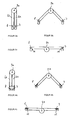
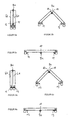
- Figures 3 to 6 each show a transverse strut 6 of the folding carriage 1 according to the invention from above.
- the figures 3a, 4a, 5a and 6a refer to the position of the respective cross member 6 in the folded state of the folding carriage 1
- Figures 3b, 4b, 5b and 6b refer to the position of the respective cross member 6 in the partially unfolded state of the folding carriage 1
- Figures 3c, 4c, 5c and 6c refer to the position of the respective cross member 6 in the fully unfolded and thus ready state of the folding carriage. 1
- FIG. 3 a the two transverse strut halves 6 a, 6 b of the transverse strut of the folding carriage 1 shown above are shown in a parallel arrangement.
- the two the axes of rotation 7, 8 adjacent inner edges of the cross-brace halves 6a, 6b show each other.
- the inner edges of the pillars 4a of the carriage frame 4 and the inner edges of the cross-strut halves 6a, 6b form an angle of 0 °.
- FIG. 4 shows the situation in the folded state of the carriage 1, in which the two transverse strut halves 6a, 6b parallel to each other and its two ends via respective attached to the outer edge of the crossbar halves stop elements 11 with the lateral supports 4a of the two Slide frame 4 are connected.
- the ends of the transverse strut halves 6a, 6b move apart (FIG. 4b) until, in the unfolded state, the abutment elements 11 abut the outer side surface of each of the cross strut halves 6a, 6b against the inner sides of the side supports 4a Force carriage frame 4.
- the thus achieved contact of the abutting stop surfaces stabilizes the rotational position of the axes of rotation 7, 8 and ensures the stability of the folding carriage.
- FIG. 6 A comparable embodiment is shown in Figure 6: However, there the stop 13 is attached to the respective side support 4a of the carriage frame 4 and contributes to the particular stabilization in that when the carriage is opened, the cross-strut halves 6a, 6b at least over part of their respective axes of rotation 7, 8 adjacent surfaces come with the stop 13 in Appendix ( Figure 6c). This limitation of the rotational position of the axes of rotation 7, 8 stabilizes the folding carriage in the unfolded state.
- the pins or pins can engage in an end position of the rotational position in the unfolded state of the folding carriage 1 or clamp or lock the axle and stabilize the slide frame by the resulting frictional connection between the axes of rotation and the cross braces.
- the rotational position of at least one of the axes of rotation 7, 8, preferably both axes of rotation of at least one transverse strut, more preferably both axes of rotation 7, 8 of both crossbars 6, by at least one locking device 20th , 21, 22, 23, 24 are positively locked.
- Such a frictional locking can be effected by numerous, the skilled person for such locking purposes locking devices. Non-limiting examples of this are handle screws or clamping screws (see “20" in Figure 1), locking handles, clamping handles, latching pins, quick release, etc.
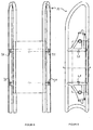
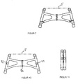
- Figures 8 to 10 show slots in which a pin or bolt engages, so that a movement about the axis by more than 90 ° is not possible because the pin or bolt prevents this.
- Such bolts can be configured for example as a snap-in bolt, handle screw, clamping screw or locking handle.
- Such locking devices 20, 21, 22, 23, 24 may individually or may be provided to several. Further, it is preferably possible according to the invention that one or more such locking device (s) instead of at least one stop, as described above, is used to stabilize the folding carriage 1 according to the invention, or that one or more such locking device (s) together with at least one Stop 10, 11, 12, 13, 14 are used to limit the rotational position of at least one of the axes of rotation of the transverse strut (s). Particularly preferred according to the invention is the use of at least one stop together with at least one locking device for stabilizing the folding carriage. 1
- both axes of rotation 7, 8 at least one transverse strut 6, preferably both transverse struts 6, is effectively prevented in the plane of each carriage frame 4 parallel or at an angle to each other arranged rotary axes 7, 8 that the two carriage frame 4 relative to each other in the longitudinal direction of Folding carriage can be moved.
- additional stabilization of the carriage construction can be achieved by additionally providing one or more locking devices 40, 41 on one or both of the transverse strut hinge shafts 9a.
- the combination of this known type of stabilization with the stabilizing devices according to the present invention, in particular the limitations of the rotational position (s) of at least one of the lateral axes of rotation 7, 8, preferably of all axes of rotation 7, 8, of the folding carriage 1 leads to exceptionally stable folding slide constructions according to the invention.
- the seat 5 of the folding carriage 1 can be any known, for these purposes known from the prior art folding slide seat. Seats made of cloth (for example canvas), belts, wood, plastic, etc. are just some examples.
- a folding carriage 1 is provided, in which the seat 5 as at least two rigid seat parts 5a, 5b comprehensive hinge is formed, wherein the respective outer longitudinal sides of each on each side closest to the seat rails 3, 3 are arranged pivotably and longitudinally non-displaceably on the respective seat strips 3, 3 and the inner longitudinal sides of the at least two rigid seat parts 5a, 5b via at least one parallel to the seat strips. 3 , 3 oriented and longitudinally non-displaceable hinge axis 5c are interconnected.
- Folding carriage of the type described above are characterized by a high stability in the unfolded state. Even significant vibration of the carriage, for example, by bumps, at high speed or considerable load on the carriage, resulting in no destabilization by longitudinal displacements of the carriage frame relative to each other.
- means for locking the rotational state of at least one of the hinge axes 9a are provided on at least one of the transverse struts 6.
- means for locking both hinge axles 9a are provided on both transverse struts 6.
- folding carriage 1 is particularly preferred, in which the cross-strut halves 6a, 6b in their central region bearing surfaces which rotation of the hinges about the hinge axis 9a on the in the unfolded state of the carriage substantially stretched state of the transverse struts 6 addition prevent.
- the stability of the folding carriage 1 according to the invention is further increased.
- the transverse struts 6 comprise in their middle region a combination of a pin on one of the crossbar halves 6a with a cover enclosing the hinge axis 9a with an opening concentric with the outer periphery of the cover on the other of the crossbar halves 6b.
- the on the spigot half 6a fixed to a crosspiece engages in the opening of the cover mounted on the other transverse strut half 6b in such a way that, in the completely folded and completely unfolded state of the carriage 1, it bears against the respective ends of the opening.
- the rotational position of the hinge axes 9a can be limited in the unfolded state of the folding carriage 1 in a reliable manner and can thus be given the carriage additional stability.
- the cross struts 6 abut the seat 5 in the unfolded state.
- the cross struts the seat 5 by means of one or more spacers support abutment.
- spacers may in a further preferred embodiment of the invention consist of an elastic material (such as rubber, plastic) and thus have a certain elasticity. They may alternatively be attached to the cross braces (halves) 6a, 6b or to the underside of the seat 5 or also to both the cross brace halves 6a, 6b and the seat 5.
- the carriage 1 may serve to further increase the stability of the carriage and therefore be particularly preferred at least one, more preferably both transverse struts 6 in the unfolded state of the carriage 1 non-positively, but releasably connected to the seat 5.
- the rotational state of the hinge axes 9a of the transverse struts 6 and the seat 5 in the unfolded state of the carriage 1 can be stabilized in a simple manner in a simple manner.
- the seat parts 5a, 5b lie between the parts of the transverse struts 6 and seat rails 4. This can be realized in a simple manner in that the two parts of the transverse struts 6 in their parallel orientation, ie in the folded state, have a mutual distance. This is possible, for example, due to the position of the hinge axis 9a outside the plane, which is defined by the transverse strut 6 associated lateral axes of rotation 7, 8.
- the hinge axis 9a of the transverse strut 6 lies on the plane defined by the transverse strut 6 associated lateral axes of rotation 7, 8.
- the respective transverse strut 6 is designed as a "double hinge", that is to say has two hinge axes, via which the two respective transverse strut halves are connected on the sides which are not facing the respective left and right rotation axes.
- a stable folding slide is also present when the hinge axes lie on the plane defined by the lateral axes of rotation associated with the respective transverse strut.
- Another possibility to realize a stable in use, but space-saving storage and transport folding carriage is to provide at least two hinge axes in the center of the seat 5, connected by at least one preferably (but not necessarily) rigid (additional) seat portion 5d are.
Landscapes
- Engineering & Computer Science (AREA)
- Chemical & Material Sciences (AREA)
- Combustion & Propulsion (AREA)
- Transportation (AREA)
- Mechanical Engineering (AREA)
- Handcart (AREA)
- Seats For Vehicles (AREA)
Applications Claiming Priority (1)
| Application Number | Priority Date | Filing Date | Title |
|---|---|---|---|
| DE200510005421 DE102005005421A1 (de) | 2005-02-05 | 2005-02-05 | Klappschlitten |
Publications (2)
| Publication Number | Publication Date |
|---|---|
| EP1688337A2 true EP1688337A2 (fr) | 2006-08-09 |
| EP1688337A3 EP1688337A3 (fr) | 2008-11-26 |
Family
ID=36591370
Family Applications (1)
| Application Number | Title | Priority Date | Filing Date |
|---|---|---|---|
| EP06002272A Withdrawn EP1688337A3 (fr) | 2005-02-05 | 2006-02-03 | Luge pliante |
Country Status (2)
| Country | Link |
|---|---|
| EP (1) | EP1688337A3 (fr) |
| DE (1) | DE102005005421A1 (fr) |
Citations (2)
| Publication number | Priority date | Publication date | Assignee | Title |
|---|---|---|---|---|
| US1070915A (en) | 1910-04-04 | 1913-08-19 | Rudolf Reisinger | Sledge. |
| DE10331991B3 (de) | 2003-07-14 | 2004-09-30 | Rudi Scheib | Klappschlitten |
Family Cites Families (2)
| Publication number | Priority date | Publication date | Assignee | Title |
|---|---|---|---|---|
| CH60225A (de) * | 1912-05-03 | 1913-07-01 | Ludwig Krohne | Zusammenlegbarer Schlitten |
| DE8516572U1 (de) * | 1985-06-07 | 1985-07-18 | Schindler, Werner, 6300 Gießen | Zusammenklappbarer Rodelschlitten |
-
2005
- 2005-02-05 DE DE200510005421 patent/DE102005005421A1/de not_active Withdrawn
-
2006
- 2006-02-03 EP EP06002272A patent/EP1688337A3/fr not_active Withdrawn
Patent Citations (2)
| Publication number | Priority date | Publication date | Assignee | Title |
|---|---|---|---|---|
| US1070915A (en) | 1910-04-04 | 1913-08-19 | Rudolf Reisinger | Sledge. |
| DE10331991B3 (de) | 2003-07-14 | 2004-09-30 | Rudi Scheib | Klappschlitten |
Also Published As
| Publication number | Publication date |
|---|---|
| DE102005005421A1 (de) | 2006-08-10 |
| EP1688337A3 (fr) | 2008-11-26 |
Similar Documents
| Publication | Publication Date | Title |
|---|---|---|
| DE3337493C2 (de) | Zusammenfaltbarer Kindersportwagen | |
| DE202013012410U1 (de) | Kinderwagen | |
| DE2222056A1 (de) | Zusammenklappbarer Artikel | |
| WO2014173477A1 (fr) | Fauteuil roulant pliable | |
| DE602004012693T2 (de) | Zusammenklappender Kinderwagen | |
| DE102019125729B3 (de) | Faltbarer Strukturrahmen für einen Wagen | |
| DE2535988C3 (de) | Zusammenklappbarer Kindersportkarren | |
| EP2837544B1 (fr) | Charrette de dimension réductible | |
| EP3571108B1 (fr) | Cadre de voiture d'enfant | |
| DE19538080A1 (de) | Transportvorrichtung für leichte Boote, Surfboards und dgl. | |
| EP1644236B1 (fr) | Luge pliante | |
| DE102006017047B3 (de) | Glastransportgestell | |
| EP1688337A2 (fr) | Luge pliante | |
| DE60010832T2 (de) | Tischart welche mit mindestens einem faltbaren Fuss oder Untergestell versehen ist | |
| DE102011012610A1 (de) | Kinderwagen | |
| DE10046512B4 (de) | Sicherungsvorrichtung zur Lagefixierung von insbesondere hochgeklappten Teilen eines Fahrzeugsitzes | |
| DE102006011852B3 (de) | Fahrgerät für eine Krankentrage oder Bahre | |
| EP2151175A2 (fr) | Table de kermesse ou banc | |
| DE2530769A1 (de) | Aus zwei haelften bestehende tischtennisplatte | |
| DE102016014117B3 (de) | Dreirädrige Gehhilfe (Delta-Gehrad), in Höhe und Breite faltbar | |
| DE102013015383A1 (de) | Klappschlitten | |
| EP3205556A1 (fr) | Cadre pour une remorque de bicyclettes ou poussette | |
| EP1707468B1 (fr) | Luge pliante | |
| DE202025104385U1 (de) | Faltbarer Strukturrahmen für einen Wagen | |
| DE558258C (de) | Sitz- und Liegemoebel mit zusammenklappbarem Rahmen |
Legal Events
| Date | Code | Title | Description |
|---|---|---|---|
| PUAI | Public reference made under article 153(3) epc to a published international application that has entered the european phase |
Free format text: ORIGINAL CODE: 0009012 |
|
| AK | Designated contracting states |
Kind code of ref document: A2 Designated state(s): AT BE BG CH CY CZ DE DK EE ES FI FR GB GR HU IE IS IT LI LT LU LV MC NL PL PT RO SE SI SK TR |
|
| AX | Request for extension of the european patent |
Extension state: AL BA HR MK YU |
|
| PUAL | Search report despatched |
Free format text: ORIGINAL CODE: 0009013 |
|
| AK | Designated contracting states |
Kind code of ref document: A3 Designated state(s): AT BE BG CH CY CZ DE DK EE ES FI FR GB GR HU IE IS IT LI LT LU LV MC NL PL PT RO SE SI SK TR |
|
| AX | Request for extension of the european patent |
Extension state: AL BA HR MK YU |
|
| 17P | Request for examination filed |
Effective date: 20090526 |
|
| 17Q | First examination report despatched |
Effective date: 20090626 |
|
| AKX | Designation fees paid |
Designated state(s): AT CH DE LI |
|
| GRAJ | Information related to disapproval of communication of intention to grant by the applicant or resumption of examination proceedings by the epo deleted |
Free format text: ORIGINAL CODE: EPIDOSDIGR1 |
|
| GRAP | Despatch of communication of intention to grant a patent |
Free format text: ORIGINAL CODE: EPIDOSNIGR1 |
|
| STAA | Information on the status of an ep patent application or granted ep patent |
Free format text: STATUS: THE APPLICATION HAS BEEN WITHDRAWN |
|
| 18W | Application withdrawn |
Effective date: 20100729 |