EP1688533B2 - Muldenmangel - Google Patents
Muldenmangel Download PDFInfo
- Publication number
- EP1688533B2 EP1688533B2 EP06008611.3A EP06008611A EP1688533B2 EP 1688533 B2 EP1688533 B2 EP 1688533B2 EP 06008611 A EP06008611 A EP 06008611A EP 1688533 B2 EP1688533 B2 EP 1688533B2
- Authority
- EP
- European Patent Office
- Prior art keywords
- drive
- trough
- ironer
- mangle
- lever
- Prior art date
- Legal status (The legal status is an assumption and is not a legal conclusion. Google has not performed a legal analysis and makes no representation as to the accuracy of the status listed.)
- Expired - Lifetime
Links
Images


Classifications
-
- D—TEXTILES; PAPER
- D06—TREATMENT OF TEXTILES OR THE LIKE; LAUNDERING; FLEXIBLE MATERIALS NOT OTHERWISE PROVIDED FOR
- D06F—LAUNDERING, DRYING, IRONING, PRESSING OR FOLDING TEXTILE ARTICLES
- D06F65/00—Ironing machines with rollers rotating against curved surfaces
- D06F65/02—Ironing machines with rollers rotating against curved surfaces with one roller only
- D06F65/08—Ironing machines with rollers rotating against curved surfaces with one roller only the roller being urged against the bed
-
- D—TEXTILES; PAPER
- D06—TREATMENT OF TEXTILES OR THE LIKE; LAUNDERING; FLEXIBLE MATERIALS NOT OTHERWISE PROVIDED FOR
- D06F—LAUNDERING, DRYING, IRONING, PRESSING OR FOLDING TEXTILE ARTICLES
- D06F65/00—Ironing machines with rollers rotating against curved surfaces
-
- D—TEXTILES; PAPER
- D06—TREATMENT OF TEXTILES OR THE LIKE; LAUNDERING; FLEXIBLE MATERIALS NOT OTHERWISE PROVIDED FOR
- D06F—LAUNDERING, DRYING, IRONING, PRESSING OR FOLDING TEXTILE ARTICLES
- D06F67/00—Details of ironing machines provided for in groups D06F61/00, D06F63/00, or D06F65/00
- D06F67/10—Driving arrangements
Definitions
- the invention relates to a bowl ironer according to the preamble of claim 1.
- a bowl ironer is, for example, off WO 93/06292 A1 known.
- the invention relates to flatwork ironers that are used in commercial laundries. It depends on the performance of such defects. High ironing capacities are achieved with known flatwork ironers by providing them with two or an even larger number of ironer rollers lying one behind the other. A curved ironer trough is assigned to each individual ironer roller. The laundry items are moved along the successive mangle troughs by the mangle rollers. To transfer the laundry items from one ironer trough to the other, arched bridges are arranged between successive ironer troughs. To move the laundry items along the bridges, conveying means are provided, which are usually so-called ironer belts. The bridges and the ironer belts require additional expenditure in the production of such flat ironers.
- the invention is based on the object of creating a bowl ironer for commercial laundries, in particular, which has a high ironing capacity but does not have the disadvantages mentioned at the beginning.
- a bowl mangle for solving the object mentioned at the beginning has the features of claim 1. Accordingly, that end face of the ironer roller to which a drive is assigned (drive side) is carried by the drive. In particular, the drive side of the ironer roller is mounted in the drive unit. This eliminates the need for a separate bearing for the ironer roller on the drive side. In addition, the structural dimensions are reduced because, due to the lack of a separate bearing on the drive side, the drive can be placed closer to the relevant face of the ironer roller.
- the drive side of the ironer roller is mounted on an output shaft of the drive, in particular a transmission of the same. Due to its design, the output shaft of the gear unit has an inner bearing that is suitable for absorbing the bearing forces of the ironer roller on the drive side.
- the ironer roller is connected to the drive, in particular the transmission, according to a preferred embodiment of the invention via a coupling flange.
- This separate coupling flange can be provided with a torque-transmitting means for connection to the transmission and can be flanged to the relevant end face of the ironer roller in a simple manner by means of screws. This enables the drive, in particular the gear, to be connected to the ironer roller which is easy to produce and, if necessary, can be easily replaced.
- the drive mechanism is designed as a planetary gear. It is thus possible to reduce the drive speed of a motor, in particular an electric motor, to the relatively low speed of the ironer roller, which in particular has a large diameter.
- the planetary gear makes it possible to bring about large transmission ratios with small structural dimensions.
- the output shaft of the planetary gear has a relatively high load-bearing capacity, which allows the ironer roller on the drive side to be mounted directly on the output shaft of the planetary gear.
- a planetary bevel gear is preferably used.
- the electric motor used to drive the ironer roller can be flanged onto the planetary angular gear with a longitudinal axis aligned perpendicular to the longitudinal axis of the ironer roller. This leads to a particularly compact structural design of the drive side of the bowl ironer.
- it can alternatively also be a cyclo gear or a harmony drive gear.
- the ironer roller is pivotably connected to a frame both on the drive side and on the opposite side, namely the drive-free side, via a lever drive.
- the lever drives make it possible to connect ironer rollers with large diameters and correspondingly high weights, but also high pressure forces to the ironer trough, in a stable manner with the frame.
- the lever drives of the drive side and the drive-free side are coupled to one another. This is preferably done using a balance shaft. This brings about a synchronization of the opposite end faces of the ironer roller associated lever drives, so that the ironer roller can be moved up and down without the longitudinal center axis of the ironer roller changing in direction.
- the balance shaft is arranged on a pivot axis of such a lever of each lever drive on which the ironer roller is mounted.
- the balance shaft can be part of the pivotable mounting of the lever drives and at the same time connect the levers in such a way that they are equally pivoted, the balance shaft being rotatable about its longitudinal central axis forming the pivot points of the levers.
- the balancing shaft is dimensioned or designed such that it essentially is torsion-free.
- the weight of the drive mounted on the drive side on the lever drive can be compensated, specifically in particular geometrically or mechanically and / or hydraulically or pneumatically.
- the ironer roller which is relatively large in diameter, requires a powerful drive.
- This drive, and in particular the planetary angular gear, has a weight that has a noticeable effect on the pressing force of the ironer roller against the ironer trough. Since this weight force caused by the dead weight of the drive is only present on the drive side, it is compensated according to the invention by increasing the pressure force of the ironer roller exerted by the lever drive on the ironer trough according to the weight of the drive on the opposite side on the drive-free side.
- the lever of the lever drive on which a pressure cylinder engages the ironer trough to press the ironer roller is correspondingly longer on the drive-free side than on the drive side.
- the weight of the drive can also be compensated hydraulically or pneumatically, for example by the pressure cylinder having a larger piston surface on the drive-free side and thereby generating a pressing force of the ironer roller against the ironer trough that is greater than the weight of the drive.
- different pressures can also be applied to the pressure medium cylinders.
- the piston surfaces of the pressure medium cylinders can also be of the same size, that is to say the same pressure medium cylinders can be used.
- the elastic ironer trough can be formed from interconnected trough sections
- each trough section extends over the entire length of the ironer roller.
- each trough section is designed to be self-sufficient. This applies in particular to your (heating) energy supply. Accordingly, each trough section has its own connections for supplying and removing the (heating) energy, for example steam, hot oil or the like. As a result, the trough sections only have to be connected to one another to form the ironer trough.
- the ironer trough can be composed of two trough sections of the same size, which each extend over approximately a quarter of the circumference of the ironer roller.
- the two trough sections (in relation to the circumferential direction of the ironer roller) are connected to one another in the middle, that is to say approximately at the lower apex of the semicircular ironer trough. This connection is made by at least one weld seam running continuously in the longitudinal direction of the ironer trough.
- This weld seam is designed and dimensioned in such a way that it has a moment of resistance that corresponds to the moment of resistance of the trough sections, which are usually double-walled, so that the elasticity behavior of the trough deficiency composed of the trough sections in the area of the connection of the trough sections is approximately the same as in the adjacent ones Areas of the ironer trough, which is formed by the trough sections.
- the ironer roller can be provided with a wrapping which has a thickness between 6 and 25 mm, in particular 12 to 20 mm. Such a wrapping withstands the loads that arise when a larger ironer roller is pressed against the ironer trough.
- the wrapping is preferably designed as a single layer, but this does not rule out the possibility that the single-layer wrapping itself can be formed from several layers.
- the single-layer wrapping is closed endlessly in the circumferential direction of the ironer roller by an essentially seamless or at least almost stepless connection seam. As a result, the laundry items to be smoothed are pressed evenly against the flattening surface of the ironer trough at all points on the circumference of the ironer roller by the winding of the ironer roller.
- the wrapping designed in this way also withstands the great pressures that the ironer roller exerts on the ironer trough.
- the wrapping is preferably formed from a felt or felt-like material. Due to the thickness specially selected according to the invention, this has the necessary resilience properties, which means that when winding the flatwork ironer according to the invention, the springs common with conventional flatwork ironers can be dispensed with, which would not or not permanently withstand the pressures that arise with flatwork ironers with large diameters of the ironer rollers . If necessary, however, the (heavy-duty) springs that withstand the loads that occur can be provided.
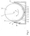
- the figures show a bowl ironer for commercial laundries.
- the trough ironer has a cylindrical ironer roller 10 which can be driven to rotate about a longitudinal center axis 11. According to the invention, the ironer roller 10 shown here has a diameter of approximately 2,000 mm.
- a flexible ironer trough 12 is assigned to the ironer roller 10. The ironer trough 12 surrounds approximately the lower half of the ironer roller 10, so that the ironer trough 12 is approximately semicircular in cross section.
- the ironer trough 12 is preferably supported continuously on opposite longitudinal edges 13 and 14 on a fixed frame 15 of the ironer.
- the Indian Fig. 1 The right longitudinal edge 13 of the ironer trough 12 is assigned to an inlet side 16 of the trough ironer and is firmly connected to the frame 15.
- the opposite longitudinal edge 14 on an outlet side 17 is movably supported on the frame 15 via a slightly inclined pendulum support 18, preferably continuous in the longitudinal direction of the ironer trough 12.
- This storage can be based on the type of DE 197 02 644 A1 be designed, to which reference is made in full and from the details of the storage, in particular the pendulum support 18, emerge.
- the ironer trough 12 can be provided with an upward-pointing extension, which runs in a straight line and somewhat obliquely, in such a way that the longitudinal edges 13 and 14 are at a distance from the ironer roller 10 to form a gap the inlet side 16 and the outlet side 17.
- Such a gap especially facilitates the introduction of the missing items of laundry between the ironer roller 10 and the ironer trough 12.
- the elastic ironer trough 12 nestles in the semicircular area on the cylindrical surface of the ironer roller 10, so that the Items of laundry between the ironer roller 10 and an inner flattening surface 19 of the ironer trough 12 are moved along through the trough ironer by the ironer roller 10, which is driven clockwise (drive direction 20) in the exemplary embodiment shown Fig. 1
- the gap shown between the ironer trough 12 and the ironer roller 10 is only used for illustration and explanatory purposes; in fact, it is not present when operating the bowl ironer.
- the elastic ironer trough 12 is formed from two trough halves 21 and 22 in the trough ironer shown here.
- the trough halves 21 and 22 are connected on a connecting line 23 running in the longitudinal direction of the mangle roller 10.
- the connecting line 23 extends through a vertical longitudinal center plane of the trough ironer lying on the longitudinal center axis 11 of the ironer roller 10.
- the two trough halves 21 and 22, apart from their mirror-image arrangement around the longitudinal center axis of the trough ironer, are designed essentially the same.
- each trough half 21 and 22 is double-walled.
- each trough half 21 and 22 has a thicker inner trough plate 24 and a thinner outer trough plate 25.
- the inner sides of the inner trough plates 24 of both trough halves 21 and 22 facing the ironer roller 10 together form the flat surface 19 of the ironer trough 12.
- the trough plates 24 and 25 are made of stainless steel, in particular stainless steel.
- the inner trough plates 24 of the trough halves 21 and 22 of the same thickness are approximately 2 to 31 ⁇ 2 times as thick as the outer trough plates 25 of the trough halves 21 and 22, which are also equally thick.
- the thickness of the inner trough plates 24 is in the range of 4 to 6 mm. Accordingly, the outer trough plates 25 are 1.2 to 3 mm thick.
- the inner trough plate 24 and the outer trough plate 25 of the same are welded tightly around the edge.
- the surfaces of the trough halves 21 and 22 are provided with a preferably uniform grid of connection points 26.
- the inner trough plates 24 are additionally welded to the outer trough plates 25.
- the outer trough plates 25 are spaced apart from the inner trough plates 24, namely approximately by an amount which corresponds to the thickness of the outer trough plates 25, preferably somewhat less.
- flow channels 27 are formed within the respective trough halves 21 and 22 for the passage of heating medium, in particular steam or a heated liquid (hot oil).
- heating medium in particular steam or a heated liquid (hot oil).
- the connection of the trough plates 24, 25 both along the circumference and at the connection points 26 or longitudinal or transverse seams is carried out by welding, specifically preferably laser welding.
- each of the two trough halves 21 and 22 is designed to be self-sufficient with regard to the energy supply.
- the trough half 21 on the upper edge area facing the inlet side 16 and the trough half 22 at the upper edge area facing the outlet side 17 have at least one, preferably several, steam connections.
- each trough half 21 and 22 has connections 28 for draining condensate.
- Each trough half 21 and 22 preferably has several separate connections 28.
- each trough half 21 or 22 has five connections 28 for condensate drainage. If necessary, each trough half 21 and 22 can also have more than five connections 28. Likewise, if necessary, fewer than five connections can be provided.
- a longitudinal weld seam 29 which can optionally be formed from several individual weld seams produced one after the other.
- the longitudinal weld seam 29 is produced using a suitable, known arc welding process under protective gas. If necessary, however, other welding processes can also be used for this purpose.
- the longitudinal weld seam 29 extends over the entire thickness of the adjacent edges of the trough halves 21 and 22, namely over the sum of the thickness of the inner trough plate 24 and the outer trough plate 25, which are continuous in the area of the connecting line 23 or longitudinal weld seam 29 in the longitudinal direction of the bowl ironers abut against one another because they are already welded to form the bowl halves 21 and 22 by the weld seam surrounding each bowl half 21 and 22.
- the longitudinal weld seam 29 extends only over the thickness of the inner trough plate 24 and not also of the outer trough plate 25.
- the longitudinal weld seam 29 is subsequently processed on the inside of the ironer trough 12, for example by grinding and / or polishing, in such a way that a seamless connection of the inner surface of the inner trough plates 24 of the individual trough halves 21 and 22 and thus a flat surface 19 that is also continuous in the area of the connection point 26 arises.
- the ironer roller 10 is connected to the frame 15 at each of its two opposite end faces by a lever drive 30, 31.
- the lever drives 30 and 31 can press the ironer roller 10 into the ironer trough 12 and, if necessary, move it away from the same.
- a drive 32 is assigned to one end of the ironer roller 10. This side of the ironer roller 10 is referred to below as the drive side 33.
- the opposite end of the ironer roller 10, to which no drive is assigned, is referred to as the non-driven side 34.
- the lever drive 31 is assigned to this side.
- the ironer roller 10 is mounted directly on the drive 32 without a stub axle, specifically on an output shaft 35 of a gearbox of the drive.
- This gear is designed as a planetary angular gear 36.
- the planetary angular gear 36 has a transmission ratio (i) of 200 to 350, preferably about 300.
- i transmission ratio
- the ironer roller 10 is mounted on the drive side 33 on the output shaft 35 of the planetary bevel gear 36, which is designed as a splined shaft.
- the planetary angular gearbox 36 is driven by an electric motor 37.
- the electric motor 37 is flanged to the planetary angular gearbox 36 in such a way that the longitudinal center axis of the electric motor 37 intersects the longitudinal center axis 11 of the ironer roller 10 in an approximately horizontal direction, namely at a right angle by the longitudinal center axis of the electric motor 37 runs transversely to the longitudinal center axis 11 of the ironer roller 10.
- a coupling flange 39 is assigned to an end wall 38 of the ironer roller 10 on the drive side 33.
- a flange plate 40 of the coupling flange 39 resting on the outside of the end face 38 of the ironer roller 10 is screwed to the end wall 38.
- a polygonal profile 41 is incorporated with the flange plate 40 of the coupling flange 39.
- the polygonal profile 41 in the flange plate 40 is designed to correspond to the profile of the output shaft 35 of the planetary bevel gear 36, which is also embodied as a polygonal profile.
- the push-on sleeve 41 By inserting the output shaft 35 of the planetary angular gear 36 into the splined profile of the push-on sleeve 41, a torque-transmitting connection is established between the output shaft 35 of the planetary angular gear 36 and the ironer roller 10 on the drive side 33.
- the push-on sleeve 41 in particular the multi-spline profile thereof, is arranged concentrically to the longitudinal center axis 11 of the ironer roller 10, whereby the latter can be driven by the drive 32 to rotate about the longitudinal center axis 11 is.
- the lever drives 30, 31 on opposite sides of the ironer roller 10 are conceptually designed as parallelogram link drives. However, the lever drives 30, 31 are dimensioned differently in the embodiment shown.
- the lever drive 30 on the drive side 33 has a (lower) double lever 42 and a single lever 43 located at a distance above it.
- the double lever 42 is mounted on the frame 15 at an outer end so that it can pivot about an axis of rotation 44.
- the axis of rotation 44 runs parallel to the central longitudinal axis 11 of the ironer roller 10.
- the axis of rotation 44 is located next to and below the central longitudinal axis 11.
- the double lever 42 is articulated to a piston rod end 45 of a pneumatic cylinder 46.
- a piston underside of the pneumatic cylinder 46 is pivotably mounted on the frame 15.
- the drive specifically the planetary angular gear 36
- the planetary bevel gear 36 is mounted on a free end of the single lever 43.
- the opposite free end of the single lever 43 is mounted pivotably about an axis of rotation 47 on the frame 15. This axis of rotation 47 is located laterally next to and above the longitudinal center axis 11 of the ironer roller 10, namely in the illustrated embodiment approximately perpendicularly above the axis of rotation 44 for the double lever 42.
- the double lever 42 By extending and retracting the pneumatic cylinder 46, the double lever 42 is pivoted about the axis of rotation 44 and the drive 32 with the attached drive side 33 of the ironer roller 10 is raised or lowered.
- the single lever 43 which is also connected to the drive 32, is pivoted about the axis of rotation 47, whereby the drive 32 and the drive side 33 of the ironer roller 10 are moved up and down on an almost vertical path to move the ironer roller 10 into the ironer trough 12 and to move it out the ironer roller 10 from the ironer trough 12.
- the lever drive 31, which is basically designed like the lever drive 30 on the drive side 33, on the non-driven side 34 of the ironer roller 10 also has a double lever 32 which can be pivoted about the axis of rotation 44 and a single lever 49 which can be pivoted about the axis of rotation 47.
- the double lever 48 can also be pivoted by means of a pneumatic cylinder 50.
- a bearing 51 for the non-driven side 34 of the ironer roller 10 is articulated between the opposite outer ends of the double lever 48 and at the free end of the single lever 49. This bearing 51 is also connected to the free end of the single lever 49.
- An axle stub 53 which is firmly connected to the end wall 52 of the ironer roller 10 on the non-driven side 34 of the same and is designed as a sleeve in the exemplary embodiment shown, is supported in the bearing 51.
- the lever drives 30 and 31 are synchronized, namely in the embodiment shown by a balance shaft 54.
- the balance shaft 54 lies on the axis of rotation 44 for mounting the double levers 42 and 48 on the frame 15.
- the balance shaft 54 thus provides a torque-transmitting connection between the double levers 42 and 48 of the lever drives 30 and 31, in that they transmit the movement of one double lever 42 to the other double lever 48.
- the balancing shaft 54 also serves to support the double levers 42 and 48 on the frame 15. So that the balancing shaft 54 ensures at least almost the same pivoting of the double levers 42 and 48, the balancing shaft 54 is designed to be essentially torsionally rigid. This is achieved, for example, by appropriately dimensioning the balancing shaft 54.
- the double levers 42 and 48 of the different lever drives 30 and 31 are of different lengths. On the drive side 33, the double lever 42 is therefore somewhat shorter.
- the distances between the articulation of the bearing 51 for mounting the ironer roller 10 on the non-driven side 34 and the planetary angular gear 36 for mounting the ironer roller 10 on the drive side 33 to the axis of rotation 44 or to the balance shaft 54 are the same.
- the distances between those points with which the pneumatic cylinders 46 and 50 are articulated to the free ends of the double levers 42 and 48 with respect to the axis of rotation 44 or the balance shaft 54 are of different lengths.
- the pneumatic cylinder 50 is articulated on the non-driven side 34 at a greater distance from the axis of rotation 44 on the double lever 48 than the pneumatic cylinder 46 on the drive side 33.
- the different lengths of the double levers 42 and 48 lead to the fact that the forces with which the ironer roller 10 is pressed into the ironer trough 12, are essentially the same on both sides of the ironer roller 10, although on the drive side 33 due to the weight of the drive 32, a noticeable proportion of the pressure force of the ironer roller 10 into the ironer trough 12 is generated by the latter.
- the weight component of the drive 32 is missing on the non-driven side 34, a greater pressing force must be exerted here by the pneumatic cylinder 50, which is brought about by the longer double lever 48.
- the length ratios of the double levers 42 and 48 are coordinated so that the longer double lever 48 on the non-driven side 34 compensates for the missing weight of the drive 32 of the drive side 33, namely a correspondingly greater force on the bearing 51 of the ironer roller 10 on the not driven side 34 exercises.
- lever ratios of the lever drives 30 and 31 different in some other way so that the lever drive 30 on the drive side 33 presses the ironer roller 10 with less forces into the ironer trough 12 than the lever drive 31 on the non-driven side 34.
- double levers 42 and 48 it is also possible to design the double levers 42 and 48 to be of equal length and instead to provide a pneumatic cylinder 50 on the non-driven side 34 with a larger piston area required to compensate for the weight of the drive 32.
- an elastic wrapping surrounding the ironer roller 10 is more heavily loaded, especially in the circumferential direction, than in conventional flatwork ironers with smaller diameters of the ironer roller. For this reason, a special wrapping is provided according to the invention.
- This is formed from a single-layer felt 55 with a thickness of preferably 7 to 18 mm.
- the felt 55 itself can consist of several layers firmly connected to one another, which can have the same but also different properties. A material web of the felt 55 formed in this way is then completely wrapped once around the ironer roller 10 and the transverse edges of the material web are connected at a connection point 56 without bumps, in particular businessed.
- connection points 56 are chamfered when viewed in the cross-sectional direction of the ironer roller 10 to form inclined connection surfaces 57. Due to this inclination, the wrapping at the connection point 56 is approximately as thick as the felt 55 outside the connection point 56 57 opposite edge regions of the felt 55 for forming the wrapping are connected to one another at the connection point 56, preferably by gluing or the like. Alternatively or additionally, the connection can also be made by sewing in the area of the connection point 56.
Landscapes
- Engineering & Computer Science (AREA)
- Textile Engineering (AREA)
- Rolls And Other Rotary Bodies (AREA)
- Straightening Metal Sheet-Like Bodies (AREA)
Description
- Die Erfindung betrifft eine Muldenmangel gemäß dem Oberbegriff des Anspruchs 1. Eine solche Muldenmangel ist beispielsweise aus
WO 93/06292 A1 - Es geht bei der Erfindung um Muldenmangeln, die in gewerblichen Wäschereien eingesetzt werden. Entscheidend kommt es dabei auf die Mangelleistung solcher Mangeln an. Hohe Mangelleistungen werden bei bekannten Muldenmangeln erreicht, indem diese mit zwei oder eine noch größere Anzahl hintereinanderliegenden Mangelwalzen versehen werden. Jeder einzelnen Mangelwalze ist eine gewölbte Mangelmulde zugeordnet. Die Wäschestücke werden von den Mangelwalzen an den aufeinanderfolgenden Mangelmulden entlangbewegt. Zur Übergabe der Wäschestücke von einer Mangelmulde zur anderen sind gewölbte Brücken zwischen aufeinanderfolgenden Mangelmulden angeordnet. Zum Entlangbewegen der Wäschestücke an den Brücken sind Fördermittel vorgesehen, bei denen es sich üblicherweise um sogenannte Mangelbänder handelt. Die Brücken und die Mangelbänder erfordern einen Mehraufwand bei der Herstellung solcher Muldenmangeln. Darüber hinaus kann es bei der Übergabe der Wäschestücke von einer Mangelmulde zur anderen im Bereich der Brücken und der Mangelbänder zu Fehlfunktionen kommen, die im Extremfall zu Unterbrechungen des Mangelvorgangs führen. Schließlich hinterlassen die Mangelbänder Abdrücke auf der Wäsche, die vor allem bei Tischwäsche das optische Erscheinungsbild stören.
- Ausgehend vom Vorstehenden liegt der Erfindung die Aufgabe zugrunde, eine Muldenmangel für insbesondere gewerbliche Wäschereien zu schaffen, die über eine hohe Mangelleistung verfügt, aber die eingangs genannten Nachteile nicht aufweist.
- Eine Muldenmangel zur Lösung der eingangs genannten Aufgabe weist die Merkmale des Anspruchs 1 auf. Demnach wird diejenige Stirnseite der Mangelwalze, der ein Antrieb zugeordnet ist (Antriebsseite), vom Antrieb getragen. Insbesondere ist die Antriebsseite der Mangelwalze im Antriebsaggregat gelagert. Dadurch erübrigt sich ein separates Lager für die Mangelwalze auf der Antriebsseite. Außerdem werden die baulichen Abmessungen verringert, weil durch das fehlende separate Lager auf der Antriebsseite der Antrieb dichter an die betreffende Stirnseite der Mangelwalze platzierbar ist.
- Dabei ist die Antriebsseite der Mangelwalze auf einer Abtriebswelle des Antriebs, und zwar insbesondere eines Getriebes desselben, gelagert. Die Abtriebswelle des Getriebes weist bauartbedingt eine innere Lagerung auf, die geeignet ist, die Lagerkräfte der Mangelwalze auf der Antriebsseite aufzunehmen.
- Verbunden ist die Mangelwalze mit dem Antrieb, insbesondere dem Getriebe, gemäß einer bevorzugten Ausgestaltung der Erfindung über einen Kupplungsflansch. Dieser separate Kupplungsflansch lässt sich mit einem drehmomentübertragenden Mittel zum Anschluss an das Getriebe versehen und kann mit der betreffenden Stirnseite der Mangelwalze durch Schrauben auf einfache Weise angeflanscht werden. Dadurch ist eine einfach herstellbare und im Bedarfsfalle leicht austauschbare Verbindung des Antriebs, insbesondere des Getriebes, mit der Mangelwalze möglich.
- Zur Weiterbildung der zuvor beschriebenen Muldenmangel ist das Getriebe des Antriebs als ein Planetengetriebe ausgebildet. Damit ist es möglich, die Antriebsdrehzahl eines Motors, insbesondere eines Elektromotors, auf die relativ geringe Drehzahl der insbesondere große Durchmesser aufweisenden Mangelwalze zu reduzieren. Das Planetengetriebe ermöglicht es, große Übersetzungsverhältnisse mit kleinen baulichen Abmessungen herbeizuführen. Des weiteren verfügt die Abtriebeswelle des Planetengetriebes über eine verhältnismäßig hohe Tragfähigkeit, die es zulässt, die Mangelwalze auf der Antriebsseite direkt auf der Abtriebswelle des Planetengetriebes zu lagern. Vorzugsweise findet ein Planetenwinkelgetriebe Verwendung. Dadurch lässt sich der zum Antrieb der Mangelwalze dienende Elektromotor mit einer senkrecht zur Längsachse der Mangelwalze ausgerichteter Längsachse an dem Planetenwinkelgetriebe anflanschen. Das führt zu einer besonders kompakten baulichen Ausgestaltung der Antriebsseite der Muldenmangel. Außerdem kann es sich alternativ auch um ein Cyclo-Getriebe oder ein Harmonie-Drive-Getriebe handeln.
- Eine weitere Weiterbildung der zuvor beschriebenen Muldenmangel weist die Merkmale des Anspruchs 5 auf. Demnach ist die Mangelwalze sowohl an der Antriebsseite als auch auf der gegenüberliegenden Seite, nämlich der antriebsfreien Seite, über jeweils einen Hebeltrieb schwenkbar mit einem Gestell verbunden. Die Hebeltriebe ermöglichen es, auch Mangelwalzen mit großen Durchmessern und entsprechend hohen Gewichten, aber auch hohen Andruckkräften an die Mangelmulde stabil mit dem Gestell zu verbinden.
- Gemäß einer bevorzugten Weiterbildung der Erfindung sind die Hebeltriebe der Antriebsseite und der antriebsfreien Seite miteinander gekoppelt. Dies geschieht vorzugsweise durch eine Ausgleichswelle. Dadurch wird eine Synchronisation der gegenüberliegenden Stirnseiten der Mangelwalze zugeordneten Hebeltriebe herbeigeführt, so dass die Mangelwalze auf- und abbewegbar ist, ohne dass sich dabei die Längsmittelachse der Mangelwalze in der Richtung verändert.
- Die Ausgleichswelle ist bei einer bevorzugten Ausgestaltung der erfindungsgemäßen Muldenmangel auf einer Schwenkachse eines solchen Hebels jedes Hebeltriebs angeordnet, an dem die Mangelwalze gelagert ist. Dadurch kann die Ausgleichswelle Bestandteil der schwenkbaren Lagerung der Hebeltriebe sein und gleichzeitig die Hebel so verbinden, dass sie gleichermaßen verschwenkt werden, wobei die Ausgleichswelle um ihre die Drehpunkte der Hebel bildende Längsmittelachse verdrehbar ist. Vorzugsweise ist die Ausgleichswelle so bemessen bzw. ausgebildet, dass sie im Wesentlichen torsionsfrei ist.
- Gemäß einer bevorzugten Weiterbildung der Erfindung ist das Gewicht des auf der Antriebsseite am Hebeltrieb gelagerten Antriebs kompensierbar, und zwar insbesondere geometrisch bzw. mechanisch und/oder hydraulisch bzw. pneumatisch. Die im Durchmesser verhältnismäßig große Mangelwalze erfordert einen leistungsstarken Antrieb. Dieser Antrieb, und zwar insbesondere auch das Planetenwinkelgetriebe, verfügt über ein Gewicht, das sich merklich auf die Andruckkraft der Mangelwalze gegen die Mangelmulde auswirkt. Da diese durch das Eigengewicht des Antriebs hervorgerufene Gewichtskraft nur auf der Antriebsseite vorhanden ist, wird sie erfindungsgemäß kompensiert, indem auf der antriebsfreien Seite die durch den Hebeltrieb ausgeübte Andruckkraft der Mangelwalze an die Mangelmulde entsprechend dem Gewicht des Antriebs auf der gegenüberliegenden Seite vergrößert wird. Dieses geschieht entweder geometrisch bzw. mechanisch, indem derjenige Hebel des Hebeltriebs, an dem ein Druckmittelzylinder zum Andrücken der Mangelwalze an die Mangelmulde angreift, auf der antriebsfreien Seite entsprechend länger ist als auf der Antriebsseite. Alternativ oder zusätzlich kann aber auch die Kompensation des Gewichts des Antriebs hydraulisch oder pneumatisch erfolgen, indem zum Beispiel der Druckmittelzylinder auf der antriebsfreien Seite eine größere Kolbenfläche aufweist und dadurch eine um das Gewicht des Antriebs höhere Anpresskraft der Mangelwalze gegen die Mangelmulde erzeugt. Es können aber auch die Druckmittelzylinder mit unterschiedlichen Drücken beaufschlagt werden. Dann können die Kolbenflächen der Druckmittelzylinder auch gleich groß sein, also gleiche Druckmittelzylinder verwendet werden.
- Ferner kann die elastische Mangelmulde aus miteinander verbundenen Muldenabschnitten gebildet werden Die vorzugsweise gleich großen Muldenabschnitte der die Mangelmulde bereichsweise, vorzugsweise im Bereich einer unteren Hälfte, umgebenden Mangelmulde erstrecken sich somit nur über einen Teil des Umfangs der Mangelwalze, der von der gesamten Mangelmulde umgeben ist. In Längsrichtung der Mangelwalze hingegen erstreckt sich jeder Muldenabschnitt über die gesamte Länge der Mangelwalze. Durch die erfindungsgemäß in Umfangsrichtung erfolgende Aufteilung der Mangelmulde wird die Stabilität derselben nicht nennenswert beeinflusst, eine gewollte Flexibilität bzw. Elastizität bleibt aber erhalten. In Längsrichtung der Mangelwalze hingegen, in der die Mangelmulde vorzugsweise steif sein soll, bleibt die Steifigkeit erhalten, weil in dieser Richtung keine Teilung der Mangelmulde erfolgt.
- Des weiteren kann vorgesehen sein, die einzelnen Muldenabschnitte für sich autark auszubilden. Das gilt insbesondere hinsichtlich Ihrer (Heiz-)Energieversorgung. Demzufolge verfügt jeder Muldenabschnitt über eigene Anschlüsse zur Zu- und Abfuhr der (Heiz-)Energie, beispielsweise Dampf, heißes Öl oder dergleichen. Dadurch müssen die Muldenabschnitte zur Bildung der Mangelmulde lediglich miteinander verbunden werden.
- Ferner kann die Mangelmulde aus zwei gleich großen Muldenabschnitten zusammengesetz sein, die sich jeweils über etwa ein Viertel des Umfangs der Mangelwalze erstrecken. Die beiden Muldenabschnitte sind (bezogen auf die Umfangsrichtung der Mangelwalze) in der Mitte miteinander verbunden, also etwa im unteren Scheitelpunkt der halbkreisförmigen Mangelmulde. Diese Verbindung erfolgt durch mindestens eine in Längsrichtung der Mangelmulde durchgehend verlaufende Schweißnaht. Diese Schweißnaht ist so ausgebildet und bemessen, dass sie über einen Widerstandsmoment verfügt, das den Widerstandsmoment der üblicherweise doppelwandig ausgebildeten Muldenabschnitte entspricht, so dass das Elastizitätsverhalten der aus den Muldenabschnitten zusammengesetzten Muldenmangel im Bereich der Verbindung der Muldenabschnitte etwa genauso groß ist wie in den daran angrenzenden Bereichen der Mangelmulde, die durch die Muldenabschnitte gebildet ist. Dadurch wird erreicht, dass die aus den zusammengeschweißten Muldenabschnitten gebildete Mangelmulde über ihren gesamten Verlauf ein etwa gleiches Widerstandsmoment aufweist und dadurch über den gesamten Umfang der Mangelwalze ein gleiches Biegeverhalten aufweist, wodurch bei in die Mangelmulde gepresster Mangelwalze die Mangelmulde sich überall gleichmäßig an die Mangelwalze anschmiegt.
- Weiterhin kann die Mangelwalze mit einer Bewicklung versehen werden, die über eine Dicke zwischen 6 und 25 mm, insbesondere 12 bis 20 mm, verfügt. Eine solche Bewicklung hält den Belastungen Stand, die beim Andrücken einer größeren Mangelwalze gegen die Mangelmulde entstehen.
- Vorzugsweise ist die Bewicklung einlagig ausgebildet, was aber nicht ausschließt, dass die einlagige Bewicklung in sich aus mehreren Schichten gebildet sein kann. Die einlagige Bewicklung ist in Umfangsrichtung der Mangelwalze endlos geschlossen durch eine im Wesentlichen übergangslose bzw. mindestens nahezu absatzlose Verbindungsnaht. Dadurch wird von der Bewicklung der Mangelwalze die zu glättenden Wäschestücke an allen Stellen des Umfangs der Mangelwalze gleichmäßig an die Plättfläche der Mangelmulde gedrückt. Die so ausgebildete Bewicklung hält auch den großen Drücken, die die Mangelwalze auf die Mangelmulde ausübt, Stand.
- Gebildet ist die Bewicklung vorzugsweise aus einem Filz oder filzartigen Material. Dieses verfügt aufgrund der erfindungsgemäß besonders gewählten Dicke über die erforderlichen Federungseigenschaften, wodurch bei der Bewicklung der erfindungsgemäßen Muldenmangel auf bei herkömmlichen Muldenmangeln übliche Federn verzichtet werden kann, die den Drücken nicht oder nicht dauerhaft Stand halten würden, die bei Muldenmangeln mit großen Durchmessern der Mangelwalzen entstehen. Gegebenenfalls können aber die den auftretenden Belastungen standhaltenden (hochbelastbaren) Federn vorgesehen werden.
- Ein bevorzugtes Ausführungsbeispiel der erfindungsgemäßen Muldenmangel wird nachfolgend anhand der Zeichnung näher erläutert. In dieser zeigen:
- Fig. 1
- eine schematische Seitenansicht der Muldenmangel,
- Fig. 2
- eine Ansicht einer nicht angetriebenen Seite der Muldenmangel,
- Fig. 3
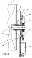
- einen Längsschnitt (entlang einer Längsmittelachse der Mangelwalze) der nicht angetriebenen Seite der Muldenmangel,
- Fig. 4
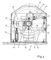
- eine Ansicht einer Antriebsseite der Muldenmangel,
- Fig. 5
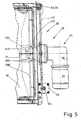
- eine Ansicht auf die Antriebsseite mit einem Antrieb,
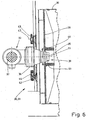
- Fig. 6
- einen vertikalen Längsschnitt durch die Antriebsseite,
- Fig.7
- eine vergrößerte Einzelheit eines Querschnitts durch die Mangelmulde im Bereich der Verbindung der Muldenhälften, und
- Fig. 8
- eine vergrößerte Einzelheit eines Querschnitts durch die Mangelwalze mit einer Bewicklung.
- Die Figuren zeigen eine Muldenmangel für gewerbliche Wäschereien. Die Muldenmangel verfügt über eine zylindrische Mangelwalze 10, die um eine Längsmittelachse 11 drehend antreibbar ist. Die hier gezeigte Mangelwalze 10 weist erfindungsgemäß einen Durchmesser von etwa 2.000 mm auf. Der Mangelwalze 10 ist eine flexible Mangelmulde 12 zugeordnet. Die Mangelmulde 12 umgibt etwa die untere Hälfte der Mangelwalze 10, so dass die Mangelmulde 12 im Querschnitt etwa halbkreisförmig ausgebildet ist.
- Die Mangelmulde 12 ist an gegenüberliegenden Längsrändern 13 bzw. 14 vorzugsweise durchgehend an einem festen Gestell 15 der Muldenmangel gelagert. Der in der
Fig. 1 rechte Längsrand 13 der Mangelmulde 12 ist einer Einlaufseite 16 der Muldenmangel zugeordnet und fest mit dem Gestell 15 verbunden. Der gegenüberliegende Längsrand 14 auf einer Auslaufseite 17 ist über eine vorzugsweise in Längsrichtung der Mangelmulde 12 durchgehende, leicht schräggestellte Pendelstütze 18 beweglich am Gestell 15 gelagert. Diese Lagerung kann nach Art derDE 197 02 644 A1 ausgebildet sein, auf die vollinhaltlich Bezug genommen wird und aus der Einzelheiten der Lagerung, insbesondere der Pendelstütze 18, hervorgehen. - Im Bereich der Einlaufseite 16 und der Auslaufseite 17 kann die Mangelmulde 12 mit einer nach oben weisenden Verlängerung versehen sein, die geradlinig und etwas schräggerichtet verläuft, und zwar derart, dass die Längsränder 13 und 14 einen Abstand zur Mangelwalze 10 aufweisen zur Bildung eines Spalts an der Einlaufseite 16 und der Auslaufseite 17. Ein solcher Spalt erleichtert vor allem das Einführen der zu mangelnden Wäschestücke zwischen die Mangelwalze 10 und die Mangelmulde 12. Die elastische Mangelmulde 12 schmiegt sich im halbkreisförmigen Bereich an die zylindrische Oberfläche der Mangelwalze 10 an, so dass die Wäschestücke zwischen der Mangelwalze 10 und einer inneren Plättfläche 19 der Mangelmulde 12 entlang durch die Muldenmangel hindurchbewegt werden durch die im gezeigten Ausführungsbeispiel im Uhrzeigersinn (Antriebsrichtung 20) angetriebene Mangelwalze 10. Der in der
Fig. 1 gezeigte Spalt zwischen der Mangelmulde 12 und der Mangelwalze 10 dient nur zu Darstellungszwecken und Erläuterungszwecken; tatsächlich ist er beim Betrieb der Muldenmangel nicht vorhanden. - Die elastische Mangelmulde 12 ist bei der hier gezeigten Muldenmangel aus zwei Muldenhälften 21 und 22 gebildet. Jede der ununterbrochen über die gesamte Längsrichtung der Muldenmangel verlaufende Muldenhälfte 21 und 22 erstreckt sich etwa über einen Viertelkreisumfang des Mantels der Mangelwalze 10. Verbunden sind die Muldenhälften 21 und 22 an einer in Längsrichtung der Mangelwalze 10 durchlaufenden Verbindungslinie 23. Die Verbindungslinie 23 erstreckt sich durch eine auf der Längsmittelachse 11 der Mangelwalze 10 liegende vertikale Längsmittelebene der Muldenmangel. Die beiden Muldenhälfte 21 und 22 sind abgesehen von ihrer spiegelbildlichen Anordnung um die Längsmittelachse der Muldenmangel im Wesentlichen gleich ausgebildet.
- Jede Muldenhälfte 21 und 22 ist doppelwandig ausgebildet. Dazu verfügt jede Muldenhälfte 21 und 22 über ein dickeres inneres Muldenblech 24 und ein dünneres äußeres Muldenblech 25. Die zur Mangelwalze 10 weisenden Innenseiten der inneren Muldenbleche 24 beider Muldenhälfte 21 und 22 bilden zusammen die Plättfläche 19 der Mangelmulde 12. Die Muldenbleche 24 und 25 sind aus Edelstahl, insbesondere rostfreiem Stahl, gebildet. Die gleichdicken inneren Muldenbleche 24 der Muldenhälften 21 und 22 sind etwa 2 bis 3½-fach so dick wie die ebenfalls gleichdicken äußeren Muldenbleche 25 der Muldenhälfte 21 und 22. Die Dicke der inneren Muldenbleche 24 liegt im Bereich von 4 bis 6 mm. Dementsprechend sind die äußeren Muldenbleche 25 1,2 bis 3 mm dick.
- Zur Bildung der jeweiligen Muldenhälfte 21 und 22 sind das innere Muldenblech 24 und das äußere Muldenblech 25 derselben ringsherum am Rand dicht verschweißt. Darüber hinaus sind die Flächen der Muldenhälften 21 und 22 mit einem vorzugsweise gleichmäßigen Raster von Verbindungsstellen 26 versehen. In den Bereichen der Verbindungsstellen 26 sind die inneren Muldenbleche 24 mit den äußeren Muldenblechen 25 zusätzlich verschweißt. Zwischen den einzelnen Verbindungsstellen 26 sind die äußeren Muldenbleche 25 von den inneren Muldenblechen 24 beabstandet, und zwar etwa um einen Betrag, der der Dicke der äußeren Muldenbleche 25 entspricht, vorzugsweise etwas geringer ist. In denjenigen Bereichen, in denen die Muldenbleche 24 und 25 voneinander beabstandet sind, werden innerhalb der jeweiligen Muldenhälfte 21 und 22 Strömungskanäle 27 zum Hindurchleiten von Heizmedium, insbesondere Dampf oder eine aufgeheizte Flüssigkeit (heißes Öl) gebildet. Alternativ ist es denkbar, im Bereich der Fläche der Muldenhälften 21 und 22 die Muldenbleche 24 und 25 durch Längsnähte oder Quernähte miteinander zu verbinden. Die Verbindung der Muldenbleche 24, 25 sowohl entlang des Umfangs als auch an den Verbindungsstellen 26 bzw. Längs- oder Quernähten erfolgt durch Schweißen, und zwar vorzugsweise Laserschweißen.
- Jede der beiden Muldenhälften 21 und 22 ist hinsichtlich der Energiezufuhr autark ausgebildet. Dazu verfügt die Muldenhälfte 21 am zur Einlaufseite 16 weisenden oberen Randbereich und die Muldenhälfte 22 am zur Auslaufseite 17 weisenden oberen Randbereich über mindestens einen, vorzugsweise mehrere, Dampfanschlüsse. Am unteren Rand, nahe der Verbindungslinie 23, verfügt jede Muldenhälfte 21 und 22 über Anschlüsse 28 zur Kondensatabfuhr. Vorzugsweise verfügt jede Muldenhälfte 21 und 22 über mehrere separate Anschlüsse 28. Im gezeigten Ausführungsbeispiel weist jede Muldenhälfte 21 bzw. 22 fünf Anschlüsse 28 zur Kondensatableitung auf. Bei Bedarf kann jede Muldenhälfte 21 und 22 auch mehr als fünf Anschlüsse 28 aufweisen. Ebenso können gegebenenfalls weniger als fünf Anschlüsse vorgesehen sein.
- An der in Längsrichtung der Muldenmangel durchgehend verlaufenden Verbindungslinie 23 sind zueinandergerichtete Ränder der Muldenhälften 21 und 22 miteinander verschweißt, und zwar durch eine Längsschweißnaht 29, die gegebenenfalls aus mehreren nacheinander hergestellten Einzelschweißnähten gebildet sein kann. Die Längsschweißnaht 29 wird nach einem geeigneten, bekannten Lichtbogenschweißverfahren unter Schutzgas hergestellt. Gegebenenfalls können hierfür aber auch andere Schweißverfahren zum Einsatz kommen. Die Längsschweißnaht 29 erstreckt sich bei einer Ausführungsform der Erfindung über die gesamte Dicke der benachbarten Ränder der Muldenhälften 21 und 22, nämlich über die Summe der Dicke des inneren Muldenblechs 24 und des äußeren Muldenblechs 25, die im Bereich der Verbindungslinie 23 bzw. Längsschweißnaht 29 durchgehend in Längsrichtung der Muldenmangel aneinander anliegen, weil sie bereits zur Bildung der Muldenhälften 21 und 22 verschweißt sind durch die jede Muldenhälfte 21 und 22 ringsherum umgebende Schweißnaht. Alternativ kann es ausreichen, dass sich die Längsschweißnaht 29 nur über die Dicke des inneren Muldenblechs 24 und nicht auch des äußeren Muldenblechs 25 erstreckt. Die Längsschweißnaht 29 ist an der Innenseite der Mangelmulde 12 nachträglich durch zum Beispiel Schleifen und/oder Polieren derart bearbeitet, dass eine übergangslose Verbindung der Innenfläche der inneren Muldenbleche 24 der einzelnen Muldenhälften 21 und 22 und damit eine auch im Bereich der Verbindungsstelle 26 durchgehende Plättfläche 19 entsteht.
- Die Mangelwalze 10 ist an jeder ihrer beiden gegenüberliegenden Stirnseiten durch einen Hebeltrieb 30, 31 mit dem Gestell 15 verbunden. Durch die Hebeltriebe 30 und 31 kann die Mangelwalze 10 in die Mangelmulde 12 gedrückt werden und bei Bedarf von derselben wegbewegt werden. Einer Stirnseite der Mangelwalze 10 ist ein Antrieb 32 zugeordnet. Diese Seite der Mangelwalze 10 wird nachfolgend als Antriebsseite 33 bezeichnet. Die gegenüberliegende Stirnseite der Mangelwalze 10, der kein Antrieb zugeordnet ist, wird als nicht angetriebene Seite 34 bezeichnet. Dieser Seite ist der Hebeltrieb 31 zugeordnet.
- Auf der Antriebsseite 33 ist die Mangelwalze 10 ohne einen Achsstummel direkt am Antrieb 32 gelagert, und zwar auf einer Abtriebswelle 35 eines Getriebes des Antriebs. Dieses Getriebe ist als Planetenwinkelgetriebe 36 ausgebildet. Das Planetenwinkelgetriebe 36 verfügt über ein Übersetzungsverhältnis (i) von 200 bis 350, vorzugsweise etwa 300. Dadurch wird mit der Mangelwalze 10 trotz des verhältnismäßig großen Durchmessers von etwa 2.000 mm eine Umfangsgeschwindigkeit erzielt, die etwa derjenigen entspricht, die bei konventionellen Muldenmangeln mit im Durchmesser kleinerer Mangelwalze erzielbar ist, nämlich bei etwa 45 m/min liegt. Auf der als Vielkeilwelle ausgebildeten Abtriebswelle 35 des Planetenwinkelgetriebes 36 ist auf der Antriebsseite 33 die Mangelwalze 10 gelagert. Angetrieben wird das Planetenwinkelgetriebe 36 im gezeigten Ausführungsbeispiel durch einen Elektromotor 37. Der Elektromotor 37 ist derart an das Planetenwinkelgetriebe 36 angeflanscht, dass die Längsmittelachse des Elektromotors 37 etwa horizontalgerichtet die Längsmittelachse 11 der Mangelwalze 10 schneidet, und zwar unter einem rechten Winkel, indem die Längsmittelachse des Elektromotors 37 quer zur Längsmittelachse 11 der Mangelwalze 10 verläuft.
- Auf der Antriebsseite 33 ist einer Stirnwandung 38 der Mangelwalze 10 ein Kupplungsflansch 39 zugeordnet. Eine außen an der Stirnseite 38 der Mangelwalze 10 anliegende Flanschplatte 40des Kupplungsflansches 39 ist mit der Stirnwandung 38 verschraubt. Mit der Flanschplatte 40 des Kupplungsflansches 39 ist ein Vielkantprofil 41 eingearbeitet. Das Vielkantprofil 41 in der Flanschplatte 40 ist korrespondierend zum Profil der ebenfalls als Vielkantprofil ausgebildeten Abtriebswelle 35 des Planetenwinkelgetriebes 36 ausgebildet. Durch Einstecken der Abtriebswelle 35 des Planetenwinkelgetriebes 36 in das Vielkeilprofil der Aufsteckhülse 41 kommt eine drehmomentübertragende Verbindung zwischen der Abtriebswelle 35 des Planetenwinkelgetriebes 36 und der Mangelwalze 10 auf der Antriebsseite 33 zustande. Die Aufsteckhülse 41, insbesondere das Vielkeilprofil derselben, ist konzentrisch zur Längsmittelachse 11 der Mangelwalze 10 angeordnet, wodurch letztere um die Längsmittelachse 11 vom Antrieb 32 drehend antreibbar ist.
- Die Hebeltriebe 30, 31 auf gegenüberliegenden Seiten der Mangelwalze 10 sind konzeptionell gleichermaßen als Parallelogrammlenkertriebe ausgebildet. Jedoch sind die Hebeltriebe 30, 31 im gezeigten Ausführungsbeispiel unterschiedlich bemessen.
- Der Hebeltrieb 30 auf der Antriebsseite 33 verfügt über einen (unteren) Doppelhebel 42 und einen mit Abstand darüberliegenden Einfachhebel 43. Der Doppelhebel 42 ist an einem außenliegenden Ende um eine Drehachse 44 schwenkbar am Gestell 15 gelagert. Die Drehachse 44 verläuft parallel zur Längsmittelachse 11 der Mangelwalze 10. Die Drehachse 44 befindet sich neben und unterhalb der Längsmittelachse 11. An einem der Drehachse 44 gegenüberliegenden Ende ist der Doppelhebel 42 gelenkig mit einem Kolbenstangenende 45 eines Pneumatikzylinders 46 verbunden. Eine Kolbenunterseite des Pneumatikzylinders 46 ist schwenkbar am Gestell 15 gelagert. Zwischen der Drehachse 44 am einen Ende des Doppelhebels 42 und dem Kolbenstangenende 45 am anderen Ende des Doppelhebels 42 ist der Antrieb, und zwar das Planetenwinkelgetriebe 36 am Doppelhebel 42 gelagert. Des weiteren ist das Planetenwinkelgetriebe 36 an einem freien Ende des Einfachhebels 43 gelagert. Das gegenüberliegende freie Ende des Einfachhebels 43 ist schwenkbar um eine Drehachse 47 am Gestell 15 gelagert. Diese Drehachse 47 befindet sich seitlich neben und oberhalb der Längsmittelachse 11 der Mangelwalze 10, und zwar im gezeigten Ausführungsbeispiel etwa senkrecht oberhalb der Drehachse 44 für den Doppelhebel 42. Durch Ein- und Ausfahren des Pneumatikzylinders 46 wird der Doppelhebel 42 um die Drehachse 44 verschwenkt und dabei der Antrieb 32 mit der daran befestigten Antriebsseite 33 der Mangelwalze 10 angehoben oder abgesenkt. Entsprechend wird der auch mit dem Antrieb 32 verbundene Einfachhebel 43 um die Drehachse 47 verschwenkt, wodurch der Antrieb 32 und die Antriebsseite 33 der Mangelwalze 10 auf einer nahezu senkrechten Bahn auf- und abbewegt werden zum Einfahren der Mangelwalze 10 in die Mangelmulde 12 und zum Herausfahren der Mangelwalze 10 aus der Mangelmulde 12.
- Der prinzipiell wie der Hebeltrieb 30 auf der Antriebsseite 33 ausgebildete Hebeltrieb 31 auf der nicht angetriebenen Seite 34 der Mangelwalze 10 verfügt auch über einen Doppelhebel 32 der um die Drehachse 44 schwenkbar ist und einen Einfachhebel 49, der um die Drehachse 47 schwenkbar ist. Der Doppelhebel 48 ist auch durch einen Pneumatikzylinder 50 verschwenkbar. Zwischen den gegenüberliegenden äußeren Enden des Doppelhebels 48 und am freien Ende des Einfachhebels 49 ist ein Lager 51 für die nicht angetriebene Seite 34 der Mangelwalze 10 angelenkt. Dieses Lager 51 ist außerdem mit dem freien Ende des Einfachhebels 49 verbunden. Im Lager 51 stützt sich ein fest mit der Stirnwandung 52 der Mangelwalze 10 auf der nicht angetriebenen Seite 34 derselben verbundener Achsstummel 53 ab, der im gezeigten Ausführungsbeispiel als eine Hülse ausgebildet ist.
- Die Hebeltriebe 30 und 31 sind synchronisiert, und zwar im gezeigten Ausführungsbeispiel durch eine Ausgleichswelle 54. Die Ausgleichswelle 54 liegt auf der Drehachse 44 zur Lagerung der Doppelhebel 42 und 48 am Gestell 15. Die Ausgleichswelle 54 stellt somit eine drehmomentübertragende Verbindung zwischen den Doppelhebeln 42 und 48 der Hebeltriebe 30 und 31 dar, indem sie die Bewegung des einen Doppelhebels 42 auf den anderen Doppelhebel 48 überträgt. Des weiteren dient die Ausgleichswelle 54 auch dazu, die Lagerung der Doppelhebel 42 und 48 am Gestell 15 herbeizuführen. Damit die Ausgleichswelle 54 eine mindestens nahezu gleiche Verschwenkung der Doppelhebel 42 und 48 gewährleistet, ist die Ausgleichswelle 54 im Wesentlichen torsionssteif ausgebildet. Das wird beispielsweise durch eine entsprechende Bemessung der Ausgleichswelle 54 erzielt.
- Die Doppelhebel 42 und 48 der unterschiedlichen Hebeltriebe 30 und 31 sind unterschiedlich lang ausgebildet. Auf der Antriebsseite 33 ist demzufolge der Doppelhebel 42 etwas kürzer. Die Abstände der Anlenkung des Lagers 51 zur Lagerung der Mangelwalze 10 auf der nicht angetriebenen Seite 34 und des Planetenwinkelgetriebes 36 zur Lagerung der Mangelwalze 10 auf der Antriebsseite 33 zur Drehachse 44 bzw. zur Ausgleichswelle 54 sind gleich. Hingegen sind die Abstände derjenigen Stellen, mit denen die Pneumatikzylinder 46 und 50 an den freien Enden der Doppelhebel 42 und 48 angelenkt sind zur Drehachse 44 bzw. Ausgleichswelle 54 unterschiedlich lang. Dadurch ist der Pneumatikzylinder 50 auf der nicht angetriebenen Seite 34 mit größerem Abstand von der Drehachse 44 am Doppelhebel 48 angelenkt als der Pneumatikzylinder 46 auf der Antriebsseite 33. Die unterschiedlichen Längen der Doppelhebel 42 und 48 führen dazu, dass die Kräfte, mit denen die Mangelwalze 10 in die Mangelmulde 12 eingedrückt wird, auf beiden Seiten der Mangelwalze 10 im Wesentlichen gleich sind, obwohl auf der Antriebsseite 33 infolge des Gewichts des Antriebs 32 von diesem ein merklicher Anteil der Eindruckkraft der Mangelwalze 10 in die Mangelmulde 12 erzeugt wird. Da auf der nicht angetriebenen Seite 34 die Gewichtskomponente des Antriebs 32 fehlt, muss hier vom Pneumatikzylinder 50 eine größere Anpresskraft ausgeübt werden, was durch den längeren Doppelhebel 48 herbeigeführt wird. Die Längenverhältnisse der Doppelhebel 42 und 48 sind dabei so aufeinander abgestimmt, dass der längere Doppelhebel 48 auf der nicht angetriebenen Seite 34 das hier fehlende Gewicht des Antriebs 32 der Antriebsseite 33 kompensiert, nämlich eine entsprechend größere Kraft auf das Lager 51 der Mangelwalze 10 auf der nicht angetriebenen Seite 34 ausübt.
- Es ist alternativ denkbar, die Hebelverhältnisse der Hebeltriebe 30 und 31 auf andere Weise unterschiedlich zu machen, damit der Hebeltrieb 30 auf der Antriebsseite 33 die Mangelwalze 10 mit geringeren Kräften in die Mangelmulde 12 drückt als der Hebeltrieb 31 an der nicht angetriebenen Seite 34.
- Auch ist es möglich, die Doppelhebel 42 und 48 gleich lang auszubilden und statt dessen auf der nicht angetriebenen Seite 34 einen Pneumatikzylinder 50 mit einer zum Ausgleich des Gewichts des Antriebs 32 erforderlichen größeren Kolbenfläche zu versehen.
- Durch den Durchmesser der Mangelwalze 10 von etwa 2.000 mm wird eine die Mangelwalze 10 umgebende elastische Bewicklung vor allem in Umfangsrichtung höher belastet als bei herkömmlichen Muldenmangeln mit geringeren Durchmessern der Mangelwalze. Aus diesem Grund ist erfindungsgemäß eine besondere Bewicklung vorgesehen. Diese ist gebildet aus einem einlagigen Filz 55 mit einer Dicke von vorzugsweise 7 bis 18 mm. Der Filz 55 in sich kann aus mehreren fest miteinander verbundenen Schichten bestehen, die gleiche aber auch unterschiedliche Eigenschaften aufweisen können. Eine Materialbahn des so gebildeten Filzes 55 wird dann vollständig einmal um die Mangelwalze 10 herumgelegt und die Querränder der Materialbahn an einer Verbindungsstelle 56 absatzlos verbunden, insbesondere geschäftet. Dazu sind die an der Verbindungsstelle 56 zusammenzusetzenden benachbarten Querränder des Filzes 55 in Querschnittsrichtung der Mangelwalze 10 gesehen angeschrägt zur Bildung schräger Verbindungsflächen 57. Durch diese Anschrägung ist die Bewicklung an der Verbindungsstelle 56 etwa genauso dick wie der Filz 55 außerhalb der Verbindungsstelle 56. Die Verbindungsflächen 57 gegenüberliegender Randbereiche des Filzes 55 zur Bildung der Bewicklung sind an der Verbindungsstelle 56 miteinander verbunden, und zwar vorzugsweise durch Kleben oder dergleichen. Alternativ oder zusätzlich kann die Verbindung auch durch Nähen im Bereich der Verbindungsstelle 56 erfolgen.
-
- 10
- Mangelwalze
- 11
- Längsmittelachse
- 12
- Mangelmulde
- 13
- Längsrand
- 14
- Längsrand
- 15
- Gestell
- 16
- Einlaufseite
- 17
- Auslaufseite
- 18
- Pendelstütze
- 19
- Plättfläche
- 20
- Antriebsrichtung von 10
- 21
- Muldenhälfte
- 22
- Muldenhälfte
- 23
- Verbindungslinie
- 24
- inneres Muldenblech
- 25
- äußeres Muldenblech
- 27
- Strömungskanal
- 28
- Anschluss
- 29
- Längsschweißnaht
- 30
- Hebeltrieb
- 31
- Hebeltrieb
- 32
- Antrieb
- 33
- Antriebsseite
- 34
- nicht angetriebene Seite
- 35
- Abtriebswelle
- 36
- Planetenwinkelgetriebe
- 37
- Elektromotor
- 38
- Stirnwandung
- 39
- Kupplungsflansch
- 40
- Flanschplatte
- 41
- Vielkantprofil
- 42
- Doppelhebel
- 43
- Einfachhebel
- 44
- Drehachse
- 45
- Kolbenstangenende
- 46
- Pneumatikzylinder
- 47
- Drechachse
- 48
- Doppelhebel
- 49
- Einfachhebel
- 50
- Pneumatikzylinder
- 51
- Lager
- 52
- Stirnwandung
- 53
- Achsstummel
- 54
- Ausgleichswelle
- 55
- Filz
- 56
- Verbindungsstelle
- 57
- schräge Verbindungsfläche
Claims (8)
- Muldenmangel mit vorzugsweise einer umlaufend antreibbaren Mangelwalze (10) und einer der Mangelwalze (10) zugeordneten flexiblen Mangelmulde (12), wobei einer Antriebsseite (33) der Mangelwalze (10) ein Antrieb (32) zugeordnet ist, dadurch gekennzeichnet, dass der Antrieb (32) die Mangelwalze (10) auf der Antriebsseite (33) trägt, indem die Antriebsseite (33) der Mangelwalze (10) auf einer Abtriebswelle (35) des Antriebs (32) gelagert ist.
- Muldenmangel nach Anspruch 1, dadurch gekennzeichnet, dass die Antriebsseite (33) der Mangewalze (10) auf der Abtriebswelle (35) eines Getriebes des Antriebs (32) gelagert ist.
- Muldenmangel nach Anspruch 1 oder 2, dadurch gekennzeichnet, dass einer antriebsseitigen Stirnwandung (38) der Mangelwalze (10) ein mit der Stirnwandung (38) verbundener Kupplungsflansch (39) zugeordnet ist, der ein drehmomentübertragendes Mittel zur Verbindung der Mangelwalze (10) mit der Abtriebswelle (35) des Antriebs (32) aufweist, wobei das drehmomentübertragende Mittel vorzugsweise als ein Vielkeilprofil ausgebildet ist, das korrespondierend zu einem Vielkeilprofil der Abtriebswelle (35) eines Getriebes des Antriebs (32) ausgebildet ist.
- Muldenmangel nach Anspruch 2 oder 3, dadurch gekennzeichnet, dass das Getriebe als ein Planetengetriebe, ein Planetenwinkelgetriebe (36), ein Cyclo-Getriebe oder ein Harmonic-Drive-Getriebe ausgebildet ist.
- Muldenmangel nach einem dervorhergehenden Ansprüche, dadurch gekennzeichnet, dass die Mangelwalze (10) an der Antriebsseite (33) und der dieser gegenüberliegenden nicht angetriebenen Seite (34) über jeweils einen Hebeltrieb (30, 31) schwenkbar mit einem Gestell (15) verbunden ist.
- Muldenmangel nach Anspruch 5, dadurch gekennzeichnet, dass die Hebeltriebe (30, 31) auf der Antriebsseite (33) und der nicht angetriebenen Seite (34) gekoppelt sind, vorzugsweise mechanisch durch zum Beispiel eine im Wesentlichen torsionsfreie Ausgleichswelle (54), die einer Drehachse (44) derjenigen Hebel der Hebeltriebe (30, 31) zugeordnet ist, an denen die Mangelwalze (10) gelagert ist.
- Muldenmangel nach Anspruch 5 oder 6, dadurch gekennzeichnet, dass das Gewicht des auf der Antriebsseite (33) am Hebeltrieb (30) gelagerten Antriebs (32) kompensierbar ist, insbesondere geometrisch bzw. mechanisch und/oder hydraulisch/pneumatisch, wobei zur mechanischen bzw. geometrischen Kompensation der am antriebsseitigen Hebeltrieb (30) vom Antrieb (32) ausgeübten Gewichtsbelastung die Hebelverhältnisse der Hebeltriebe (30 und 31) entsprechend bemessen sind, vorzugsweise derjenige Hebelarm des Hebeltriebs (30), an dem jeweils ein Druckmittelzylinder angreift, kürzer ist als der entsprechende Hebelarm des Hebeltriebs (31) der nicht angetriebenen Seite (34), oder zur pneumatischen bzw. hydraulischen Kompensation der am antriebsseitigen Hebeltrieb (30) vom Antrieb (32) ausgeübten Gewichtsbelastung der diesem Hebeltrieb (30) zugeordnete Druckmittelzylinder eine kleinere Kolbenfläche aufweist als derjenige Druckmittelzylinder, der dem Hebeltrieb (31) der nicht angetriebenen Seite (34) der Mangelwalze (10) zugeordnet ist.
- Muldenmangel nach einem der Ansprüche 5 bis 7, dadurch gekennzeichnet, dass die Hebeltriebe (30, 31) auf der Antriebsseite (33) und auf der nicht angetriebenen Seite (34) durch Druckmittelzylinder verschwenkbar sind.
Applications Claiming Priority (3)
| Application Number | Priority Date | Filing Date | Title |
|---|---|---|---|
| DE10107120 | 2001-02-14 | ||
| DE10152641A DE10152641A1 (de) | 2001-02-14 | 2001-10-16 | Muldenmangel |
| EP02000771A EP1233101B1 (de) | 2001-02-14 | 2002-01-14 | Muldenmangel |
Related Parent Applications (2)
| Application Number | Title | Priority Date | Filing Date |
|---|---|---|---|
| EP02000771A Division EP1233101B1 (de) | 2001-02-14 | 2002-01-14 | Muldenmangel |
| EP02000771.2 Division | 2002-01-14 |
Publications (3)
| Publication Number | Publication Date |
|---|---|
| EP1688533A1 EP1688533A1 (de) | 2006-08-09 |
| EP1688533B1 EP1688533B1 (de) | 2012-05-30 |
| EP1688533B2 true EP1688533B2 (de) | 2020-11-25 |
Family
ID=7674190
Family Applications (1)
| Application Number | Title | Priority Date | Filing Date |
|---|---|---|---|
| EP06008611.3A Expired - Lifetime EP1688533B2 (de) | 2001-02-14 | 2002-01-14 | Muldenmangel |
Country Status (2)
| Country | Link |
|---|---|
| EP (1) | EP1688533B2 (de) |
| DE (1) | DE10152641A1 (de) |
Citations (8)
| Publication number | Priority date | Publication date | Assignee | Title |
|---|---|---|---|---|
| US2157086A (en) † | 1938-02-14 | 1939-05-02 | Empire Ironer Inc | Ironer |
| GB508184A (en) † | 1937-11-24 | 1939-06-27 | British Thomson Houston Co Ltd | Improvements in and relating to ironing machines |
| GB534061A (en) † | 1938-12-22 | 1941-02-26 | British Thomson Houston Co Ltd | Improvements in and relating to electric ironing machines |
| US2362322A (en) † | 1938-02-14 | 1944-11-07 | Empire Ironer Inc | Ironer |
| US2578928A (en) † | 1945-12-12 | 1951-12-18 | Conlon Moore Corp | Portable domestic ironing machine with friction drive |
| US2614347A (en) † | 1947-12-05 | 1952-10-21 | Conlon Moore Corp | Portable domestic ironing machine |
| US2956356A (en) † | 1958-06-18 | 1960-10-18 | Ironrite Inc | Ironing machine |
| US3118241A (en) † | 1964-01-21 | ironing machine |
Family Cites Families (6)
| Publication number | Priority date | Publication date | Assignee | Title |
|---|---|---|---|---|
| DE748366C (de) * | 1940-09-07 | 1953-02-09 | Siemens Schuckertwerke A G | Muldenbuegelmaschine |
| DE3433780A1 (de) * | 1984-09-14 | 1986-03-27 | Helmut 5202 Hennef Katterbach | Buegelwalze, insbesondere fuer den waeschereibetrieb |
| DE3819378A1 (de) * | 1988-06-07 | 1989-12-14 | Schmitz Elasto Press | Mangelwalze mit textilauflage |
| DE9004179U1 (de) * | 1990-04-11 | 1990-07-26 | Herbert Kannegiesser Gmbh + Co, 4973 Vlotho | Mangel zum Glätten feuchter Wäschestücke |
| DE4132213A1 (de) * | 1991-09-27 | 1993-04-08 | Boewe Passat Reinigung | Reibungskraftkompensation bei einer waeschemangel |
| BE1005950A3 (nl) * | 1992-06-05 | 1994-03-15 | Lapauw Romain | Industriele strijkmachine en de werkwijze ter vervaardiging van een kuip in een dergelijke strijkmachine te gebruiken. |
-
2001
- 2001-10-16 DE DE10152641A patent/DE10152641A1/de not_active Withdrawn
-
2002
- 2002-01-14 EP EP06008611.3A patent/EP1688533B2/de not_active Expired - Lifetime
Patent Citations (8)
| Publication number | Priority date | Publication date | Assignee | Title |
|---|---|---|---|---|
| US3118241A (en) † | 1964-01-21 | ironing machine | ||
| GB508184A (en) † | 1937-11-24 | 1939-06-27 | British Thomson Houston Co Ltd | Improvements in and relating to ironing machines |
| US2157086A (en) † | 1938-02-14 | 1939-05-02 | Empire Ironer Inc | Ironer |
| US2362322A (en) † | 1938-02-14 | 1944-11-07 | Empire Ironer Inc | Ironer |
| GB534061A (en) † | 1938-12-22 | 1941-02-26 | British Thomson Houston Co Ltd | Improvements in and relating to electric ironing machines |
| US2578928A (en) † | 1945-12-12 | 1951-12-18 | Conlon Moore Corp | Portable domestic ironing machine with friction drive |
| US2614347A (en) † | 1947-12-05 | 1952-10-21 | Conlon Moore Corp | Portable domestic ironing machine |
| US2956356A (en) † | 1958-06-18 | 1960-10-18 | Ironrite Inc | Ironing machine |
Also Published As
| Publication number | Publication date |
|---|---|
| EP1688533B1 (de) | 2012-05-30 |
| DE10152641A1 (de) | 2002-08-22 |
| EP1688533A1 (de) | 2006-08-09 |
Similar Documents
| Publication | Publication Date | Title |
|---|---|---|
| CH658498A5 (de) | Presswalze an einem walzwerk, deren durchbiegung einstellbar ist. | |
| DE3025799C2 (de) | Preßwalze, deren Durchbiegung einstellbar ist | |
| DE3631802C2 (de) | ||
| DE4404634A1 (de) | Walzenmühle | |
| EP1233101A2 (de) | Muldenmangel | |
| AT392661B (de) | Presswalze, deren durchbiegung einstellbar ist | |
| EP1688533B2 (de) | Muldenmangel | |
| DE3541539A1 (de) | Trocken- und buegelmaschine | |
| DE3940744C2 (de) | Walze für eine Vorrichtung zum Bearbeiten von bahn- oder tafelförmigem Material | |
| DE19904451B4 (de) | Kalander für bahnförmige Materialien wie Papier | |
| DE3841360C2 (de) | ||
| DE69714757T2 (de) | Entnahmewalze, breitstreckwalze oder dergleichen für bahnförmiges materal | |
| DE2938580A1 (de) | Durchbiegungssteuerbare walze | |
| DE3138176C2 (de) | Als Auftragsvorrichtung dienende Walze für die Behandlung von flächigen Gebilden, z. B. Warenbahnen | |
| DE3936128C2 (de) | ||
| DE10313444A1 (de) | Vorrichtung, bei der ein erster Zylinder und ein an diesen angestellter zweiter Zylinder einen Spalt bilden | |
| EP3851221B1 (de) | Rundmaschine | |
| DE10023291A1 (de) | Beheizbare oder kühlbare Walze zur Temperaturbehandlung von Materialbahnen, insbesondere zur Verwendung für Wellpappemaschinen | |
| EP0134434B1 (de) | Walze mit hydraulisch anpassbarer Biegelinie | |
| DE9105073U1 (de) | Durchbiegungseinstellwalze | |
| WO2004035916A1 (de) | Pressvorrichtung | |
| EP2239531B1 (de) | Mit Dampf beheizbare Hohl-Walze | |
| CH627999A5 (de) | Hebe- oder pressvorrichtung, insbesondere fuer den verschiebbaren boden einer faserbandkanne fuer spinnmaschinen. | |
| DE60121737T2 (de) | Schuhpresse und schuhträger dafür | |
| WO2009146698A1 (de) | Walze mit selbsteinstellbarer durchbiegung |
Legal Events
| Date | Code | Title | Description |
|---|---|---|---|
| PUAI | Public reference made under article 153(3) epc to a published international application that has entered the european phase |
Free format text: ORIGINAL CODE: 0009012 |
|
| AC | Divisional application: reference to earlier application |
Ref document number: 1233101 Country of ref document: EP Kind code of ref document: P |
|
| AK | Designated contracting states |
Kind code of ref document: A1 Designated state(s): DE DK ES FR GB IT |
|
| 17P | Request for examination filed |
Effective date: 20070209 |
|
| 17Q | First examination report despatched |
Effective date: 20070313 |
|
| AKX | Designation fees paid |
Designated state(s): DE DK ES FR GB IT |
|
| GRAP | Despatch of communication of intention to grant a patent |
Free format text: ORIGINAL CODE: EPIDOSNIGR1 |
|
| GRAS | Grant fee paid |
Free format text: ORIGINAL CODE: EPIDOSNIGR3 |
|
| GRAA | (expected) grant |
Free format text: ORIGINAL CODE: 0009210 |
|
| AC | Divisional application: reference to earlier application |
Ref document number: 1233101 Country of ref document: EP Kind code of ref document: P |
|
| AK | Designated contracting states |
Kind code of ref document: B1 Designated state(s): DE DK ES FR GB IT |
|
| REG | Reference to a national code |
Ref country code: GB Ref legal event code: FG4D Free format text: NOT ENGLISH |
|
| REG | Reference to a national code |
Ref country code: DE Ref legal event code: R096 Ref document number: 50215500 Country of ref document: DE Effective date: 20120726 |
|
| PG25 | Lapsed in a contracting state [announced via postgrant information from national office to epo] |
Ref country code: DK Free format text: LAPSE BECAUSE OF FAILURE TO SUBMIT A TRANSLATION OF THE DESCRIPTION OR TO PAY THE FEE WITHIN THE PRESCRIBED TIME-LIMIT Effective date: 20120530 |
|
| PG25 | Lapsed in a contracting state [announced via postgrant information from national office to epo] |
Ref country code: IT Free format text: LAPSE BECAUSE OF FAILURE TO SUBMIT A TRANSLATION OF THE DESCRIPTION OR TO PAY THE FEE WITHIN THE PRESCRIBED TIME-LIMIT Effective date: 20120530 |
|
| PLBI | Opposition filed |
Free format text: ORIGINAL CODE: 0009260 |
|
| PLAX | Notice of opposition and request to file observation + time limit sent |
Free format text: ORIGINAL CODE: EPIDOSNOBS2 |
|
| 26 | Opposition filed |
Opponent name: JENSEN DENMARK A/S Effective date: 20130228 |
|
| PG25 | Lapsed in a contracting state [announced via postgrant information from national office to epo] |
Ref country code: ES Free format text: LAPSE BECAUSE OF FAILURE TO SUBMIT A TRANSLATION OF THE DESCRIPTION OR TO PAY THE FEE WITHIN THE PRESCRIBED TIME-LIMIT Effective date: 20120910 |
|
| REG | Reference to a national code |
Ref country code: DE Ref legal event code: R026 Ref document number: 50215500 Country of ref document: DE Effective date: 20130228 |
|
| PLAF | Information modified related to communication of a notice of opposition and request to file observations + time limit |
Free format text: ORIGINAL CODE: EPIDOSCOBS2 |
|
| PLBB | Reply of patent proprietor to notice(s) of opposition received |
Free format text: ORIGINAL CODE: EPIDOSNOBS3 |
|
| REG | Reference to a national code |
Ref country code: FR Ref legal event code: PLFP Year of fee payment: 14 |
|
| PGFP | Annual fee paid to national office [announced via postgrant information from national office to epo] |
Ref country code: GB Payment date: 20150204 Year of fee payment: 14 |
|
| REG | Reference to a national code |
Ref country code: FR Ref legal event code: PLFP Year of fee payment: 15 |
|
| PLAY | Examination report in opposition despatched + time limit |
Free format text: ORIGINAL CODE: EPIDOSNORE2 |
|
| PLBC | Reply to examination report in opposition received |
Free format text: ORIGINAL CODE: EPIDOSNORE3 |
|
| GBPC | Gb: european patent ceased through non-payment of renewal fee |
Effective date: 20160114 |
|
| PG25 | Lapsed in a contracting state [announced via postgrant information from national office to epo] |
Ref country code: GB Free format text: LAPSE BECAUSE OF NON-PAYMENT OF DUE FEES Effective date: 20160114 |
|
| APAH | Appeal reference modified |
Free format text: ORIGINAL CODE: EPIDOSCREFNO |
|
| APBM | Appeal reference recorded |
Free format text: ORIGINAL CODE: EPIDOSNREFNO |
|
| APBP | Date of receipt of notice of appeal recorded |
Free format text: ORIGINAL CODE: EPIDOSNNOA2O |
|
| REG | Reference to a national code |
Ref country code: FR Ref legal event code: PLFP Year of fee payment: 16 |
|
| APBQ | Date of receipt of statement of grounds of appeal recorded |
Free format text: ORIGINAL CODE: EPIDOSNNOA3O |
|
| REG | Reference to a national code |
Ref country code: FR Ref legal event code: PLFP Year of fee payment: 17 |
|
| PGFP | Annual fee paid to national office [announced via postgrant information from national office to epo] |
Ref country code: FR Payment date: 20191230 Year of fee payment: 19 |
|
| PGFP | Annual fee paid to national office [announced via postgrant information from national office to epo] |
Ref country code: DE Payment date: 20200130 Year of fee payment: 19 |
|
| APBC | Information on closure of appeal procedure deleted |
Free format text: ORIGINAL CODE: EPIDOSDNOA9O |
|
| APBU | Appeal procedure closed |
Free format text: ORIGINAL CODE: EPIDOSNNOA9O |
|
| APBU | Appeal procedure closed |
Free format text: ORIGINAL CODE: EPIDOSNNOA9O |
|
| PUAH | Patent maintained in amended form |
Free format text: ORIGINAL CODE: 0009272 |
|
| STAA | Information on the status of an ep patent application or granted ep patent |
Free format text: STATUS: PATENT MAINTAINED AS AMENDED |
|
| 27A | Patent maintained in amended form |
Effective date: 20201125 |
|
| AK | Designated contracting states |
Kind code of ref document: B2 Designated state(s): DE DK ES FR GB IT |
|
| REG | Reference to a national code |
Ref country code: DE Ref legal event code: R102 Ref document number: 50215500 Country of ref document: DE |
|
| REG | Reference to a national code |
Ref country code: DE Ref legal event code: R119 Ref document number: 50215500 Country of ref document: DE |
|
| PG25 | Lapsed in a contracting state [announced via postgrant information from national office to epo] |
Ref country code: FR Free format text: LAPSE BECAUSE OF NON-PAYMENT OF DUE FEES Effective date: 20210131 |
|
| PG25 | Lapsed in a contracting state [announced via postgrant information from national office to epo] |
Ref country code: DE Free format text: LAPSE BECAUSE OF NON-PAYMENT OF DUE FEES Effective date: 20210803 |