EP1688573B1 - Fenêtre coulissante - Google Patents
Fenêtre coulissante Download PDFInfo
- Publication number
- EP1688573B1 EP1688573B1 EP06100345.5A EP06100345A EP1688573B1 EP 1688573 B1 EP1688573 B1 EP 1688573B1 EP 06100345 A EP06100345 A EP 06100345A EP 1688573 B1 EP1688573 B1 EP 1688573B1
- Authority
- EP
- European Patent Office
- Prior art keywords
- sash
- sliding window
- window according
- outer frame
- links
- Prior art date
- Legal status (The legal status is an assumption and is not a legal conclusion. Google has not performed a legal analysis and makes no representation as to the accuracy of the status listed.)
- Expired - Lifetime
Links
Images




Classifications
-
- E—FIXED CONSTRUCTIONS
- E05—LOCKS; KEYS; WINDOW OR DOOR FITTINGS; SAFES
- E05D—HINGES OR SUSPENSION DEVICES FOR DOORS, WINDOWS OR WINGS
- E05D15/00—Suspension arrangements for wings
- E05D15/06—Suspension arrangements for wings for wings sliding horizontally more or less in their own plane
- E05D15/10—Suspension arrangements for wings for wings sliding horizontally more or less in their own plane movable out of one plane into a second parallel plane
- E05D15/1005—Suspension arrangements for wings for wings sliding horizontally more or less in their own plane movable out of one plane into a second parallel plane the wing being supported on arms movable in horizontal planes
- E05D15/1013—Suspension arrangements for wings for wings sliding horizontally more or less in their own plane movable out of one plane into a second parallel plane the wing being supported on arms movable in horizontal planes specially adapted for windows
-
- E—FIXED CONSTRUCTIONS
- E05—LOCKS; KEYS; WINDOW OR DOOR FITTINGS; SAFES
- E05D—HINGES OR SUSPENSION DEVICES FOR DOORS, WINDOWS OR WINGS
- E05D15/00—Suspension arrangements for wings
- E05D15/06—Suspension arrangements for wings for wings sliding horizontally more or less in their own plane
- E05D15/10—Suspension arrangements for wings for wings sliding horizontally more or less in their own plane movable out of one plane into a second parallel plane
- E05D2015/1028—Suspension arrangements for wings for wings sliding horizontally more or less in their own plane movable out of one plane into a second parallel plane with only the wing moving transversely
- E05D2015/1031—Suspension arrangements for wings for wings sliding horizontally more or less in their own plane movable out of one plane into a second parallel plane with only the wing moving transversely the wing supported on arms extending from the carriage
-
- E—FIXED CONSTRUCTIONS
- E05—LOCKS; KEYS; WINDOW OR DOOR FITTINGS; SAFES
- E05Y—INDEXING SCHEME ASSOCIATED WITH SUBCLASSES E05D AND E05F, RELATING TO CONSTRUCTION ELEMENTS, ELECTRIC CONTROL, POWER SUPPLY, POWER SIGNAL OR TRANSMISSION, USER INTERFACES, MOUNTING OR COUPLING, DETAILS, ACCESSORIES, AUXILIARY OPERATIONS NOT OTHERWISE PROVIDED FOR, APPLICATION THEREOF
- E05Y2900/00—Application of doors, windows, wings or fittings thereof
- E05Y2900/10—Application of doors, windows, wings or fittings thereof for buildings or parts thereof
- E05Y2900/13—Type of wing
- E05Y2900/132—Doors
-
- E—FIXED CONSTRUCTIONS
- E05—LOCKS; KEYS; WINDOW OR DOOR FITTINGS; SAFES
- E05Y—INDEXING SCHEME ASSOCIATED WITH SUBCLASSES E05D AND E05F, RELATING TO CONSTRUCTION ELEMENTS, ELECTRIC CONTROL, POWER SUPPLY, POWER SIGNAL OR TRANSMISSION, USER INTERFACES, MOUNTING OR COUPLING, DETAILS, ACCESSORIES, AUXILIARY OPERATIONS NOT OTHERWISE PROVIDED FOR, APPLICATION THEREOF
- E05Y2900/00—Application of doors, windows, wings or fittings thereof
- E05Y2900/10—Application of doors, windows, wings or fittings thereof for buildings or parts thereof
- E05Y2900/13—Type of wing
- E05Y2900/148—Windows
Definitions
- the present invention relates to a sliding window with a frame formed from frame profiles, a relative to the frame parallel exhibitable wing with Fügelrahmenprofilen which is parallel in a parallel position displaced parallel to the frame, an upper fitting is provided with two links between the sash and frame, and a lower fitting is provided with two mutually coupled arms between the wing and the frame, and a first upper arm and a first lower arm are connected via an arranged on a flight frame profile of the wing axis.
- Such a sliding window is out of the EP 916 794 known, in which on a frame a parallel aus basic wing is provided, which is guided in a position spaced from the frame frame position parallel to the frame slidably.
- two upper links and two lower links are provided, which are rotatably mounted on the side of the frame on a carriage and are rotatably supported on the wing edge on a vertical frame profile.
- An upper link and a lower link are connected to each other via a continuous shaft, so that the fitting unit is designed relatively expensive and can also be difficult to adjust.
- the Lerkers arranged at the edge lie in the visible range both with opened wings and with the wing closed and are unprotected.
- the EP-A-0 139 046 shows a push rod fitting, in which a wing is mounted on pivoting levers. At the top and the bottom of the wing while two levers are provided, which are movable via the push rod fitting in opposite directions. As a result, a wing can be moved via cam guides relative to a window frame.
- the fitting unit comprises on one side of the wing a first upper and a lower arm and spaced therefrom a second upper and a second lower arm, the second arm being spaced from a side vertical sash profile on respective upper and lower horizontal sash profiles; Distance of an axis of the second link to the upper or lower sash profile of an outer edge of the lateral vertical sash profile is greater than the length of the second link.
- an axis of rotation provided on the wing of the second upper and lower link extends in the region of a filling element within the wing. This makes it possible, when closed
- the fitting unit preferably has a C-shaped contour and is designed so that on the side of the frame, the upper link via a rod and the lower links are also connected to each other via a rod, which then on one side of the wing on a common axis together are coupled.
- the upper arm and lower arm are each movably held on a run in a running rail carriage.
- the carriages are then connected firmly to each other via a rod.
- the wing is held vertically adjustable relative to the frame, so that during assembly an adjustment can be made to accommodate the wing with the smallest possible gap dimensions in the frame can.
- the height adjustment may be possible on the first lower arm and the second lower arm to make a twist of the wing can.
- a running rail is provided at the top and bottom of the frame, on which the carriages are received with the links.
- the running rail may have an undercut groove, so that a release of the carriage is prevented.
- a lift-off can be mounted on the track to avoid jumping out of a carriage. Stops may also be mounted on the track to limit the maximum travel of the sash.
- the sliding window is preferably as a unit with a fixed glazed first area with a filling and a second area, in the closed state the wing covered, divided by a post profile.
- the fillings of the wing and the fixed glazed area preferably lie in one plane.
- Figure 10B shows two views of the track with a lift-out protection
- sliding window In FIG. 1 a sliding window is shown, wherein the term "sliding window" should be broad, so also includes elements in which the wing is designed as a door. Furthermore, it is not necessary for the sliding window to be a filling element Made of glass, as well as other non-transparent or only partially transparent filling elements can be used.
- the sliding window comprises a frame 1, which is formed circumferentially and is divided by a post 2 in a fixed glazed field 3 and a window opening 4, wherein the window opening 4 is closed by a parallel exhibitable wing 5.
- the profiles used for frame, posts and wings can be made of metal, preferably aluminum or steel, but also made of plastic or wood.
- a fitting unit which comprises an upper fitting, which has a first upper link 23 and a second upper link 24.
- the first upper arm 23 is rotatably mounted on a vertical sash profile 11, while the second arm 24 is mounted about an axis 15 on a horizontal upper sash profile 12, so that there is a distance to a marginal vertical sash profile 10.
- a lower fitting is provided, comprising a lower first arm 21 and a lower second arm 22, wherein the first lower arm 21 is rotatably mounted on the vertical casement 11 profile and the second lower arm 22 is hinged to the lower horizontal casement profile 13.
- the axis 15 of the second upper link 24 and the second lower link 22 is arranged in the region of a filling element 14, so spaced from the lateral vertical sash profile 10. As will be explained below, this makes the fitting concealed between the wing 5 and frame 1 order.
- the links 21, 22, 23 and 24 are rotatably mounted on the side of the frame 1 respectively on carriage 9, which are guided displaceably on a running rail 8.
- the upper fitting parts are covered by a bar 100 which is mounted on the frame 1.
- FIG. 2 In FIG. 2 are the fittings for the wing 5 in an exploded view with a to FIG. 1 Rear view angle shown.
- the upper links 23 and 24 are guided on the side of the frame 1 to carriage 9, which are slidably received on a running rail 52.
- the carriages 9 are connected to each other via a rod 50.
- the first lower arm 21 and the second lower arm 22 are guided on carriages 9, which are also connected to each other via a rod 51.
- the carriages 9 can be guided by means of rollers, balls or sliders within the running rail 8 and 52, respectively.
- the lower arm 21 and the first upper arm 23 are respectively mounted on bearing parts 17 and 18, wherein by means of sleeve couplings 25 and 26, a connection with a continuous shaft 20 is provided.
- the shaft 20 may also be supported with one or more bearing parts 27.
- the fitting is thus arranged C-shaped around the wing 5, as is made visible by the parts 24, 50, 23, 20, 21, 51 and 22.
- a continuous vertical shaft is not necessary in the area of the links 22 and 24.
- the carriage 9 are secured against lifting out of the running rail 8 and 52 by Aushebeschen 28.
- the Aushebeschen are set on the rod 50 and 51 respectively.
- control block 30 is still provided for controlling the window sash in the closing phase, and a stopper 31 which limits the maximum sliding path of the wing 5 along the running rail 8.
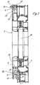
- FIG. 3 is a section through the frame 1 and the wing 5 shown.
- the wing 5 comprises a lower horizontal sash profile 13, on which a fitting groove 6 is provided for the fastening parts of the links 21 and 22.
- the fitting groove 6 is formed circumferentially on the profiles of the wing 5, so that at the profile 11, the axis 20 and the other fitting parts for supporting the axis 20 are added.
- Spaced from the groove 6, a further groove 7 is provided, which serves as a bolt fitting groove for the locking of the wing 5.
- a running rail 8 is mounted on the frame 1 for the carriage 9, wherein the running rail 8 can also be formed integrally with the frame 1.
- the links 21 and 22 are on the side of the wing 5 positively and non-positively fixed to the fitting groove 6 wherein the handlebar 22 has a rotation axis 15 which extends in the region of the insulating glass pane 14.
- a running rail 52 is provided in the upper region, in which the carriage 9 are guided.
- the running rail 52 is covered by a covering profile 53, which is arranged with a downwardly extending leg 55 at only a small distance from the upper casement profile 12.
- the fitting parts are concealed in the upper area.
- the lower part of the lower sash frame profile 13 is provided with a downwardly extending legs 56, so that here also the fitting parts are hidden.
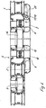
- FIG. 4 a horizontal section through the sliding window is shown, in which the subdivision of the frame 1 in fixed field 3 and window opening 4 through the post 2 is visible.
- a fitting groove 6 is formed, on which the bearing parts 17 and 18 are inserted positively and are held by the Nuthinterrough, wherein in the bearing parts 17 and 18, the axis of rotation 20 passes.
- the filling elements formed by insulating glass panes 3 and 14 of the fixed field and the wing 5 are arranged on one level.
- the bearing of the links 22 and 24 is offset towards the center, as shown schematically by a bearing bore 19.
- the bearing bore 19 may be in an area of the corner connector of the Wing 5 are, whereby the storage of the links 22 and 24 receives a special stability.
- the distance between the bearing 19 and the axis 15 of the outer edge of the vertical sash profile 10 is greater than the length of the handlebars 22 and 24.
- the movement of the wing 5 is synchronized by the links 21, 22, 23 and 24 and the rods 50 and 51, so that the wing 5 is forcibly guided on the frame 1.
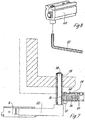
- FIGS. 5 and 6 a height adjustment 29 in the region of the lower first arm 21 is shown.
- An arranged on the handlebar 21 bearing pin 32 passes through the sliding in the fitting groove 6 fixed bearing part 18.
- the bearing pin 32 has on the bearing part 18 projecting portion a surface 33 which is connectable to the shaft 20 and a corresponding sleeve coupling part 25 and 26.
- Other attachment mechanisms may be provided.
- a horizontally arranged support member 34 is provided, which engages with a support pin 36 in a bore 37 on the bearing part 18. As a result, the support member 34 is fixed in height.
- the support member 34 is surrounded by a profile section which is penetrated by a spindle screw 35.
- the thread of the spindle screw 35 meshes with a thread on the support member 34.
- a bolt 61 is also provided, which passes through the support member 34 at a bore and is fixed to the profile section 60.
- a guide of the profile section 60 is achieved in the vertical direction and by means of the Allen key 62 can thus be made an adjustment on this page.
- FIGS. 7 and 8 a corresponding height adjustment 29 for the handlebar 22.
- a vertical bearing pin 38 is provided by a bearing sleeve 39 is surrounded.
- the bearing sleeve 39 is supported on the handlebar 22 and has a bore into which a pin 36 of a support member 34 is inserted.
- the support member 34 is again penetrated by a spindle screw 35 and a guide pin 61, wherein the support member 34, a profile section 60 is arranged.
- the profile section 60 can be adjusted in height, so that in the region of the handlebar 22, a height adjustment is possible.
- FIG. 9 is the sleeve coupling 25 and 26 shown, which is connectable to the shaft 20.
- the sleeve coupling 25, 26 has a through hole 40 which has a deviating from the circular cross-section and in which the bearing pin 30 can be inserted.
- a deviating from the circular contour contour is also given by the surface 33, so that a rotationally fixed connection between the bearing pin 32 and sleeve coupling 25 and 26 is made.
- the surface 33 are provided on the sleeve coupling 25 and 26 more Imbüsschrauben 65 by means of which the height of the sleeve coupling 25 and 26 can be fixed relative to the bearing pin 33.
- FIGS. 10A and 10B a detail view of the lift-off 28 is shown.
- the lift-off 28 has a through hole 41 and can thus be pushed onto a rod 50 or 51.
- the Aushebêt 28 can be fixed by a clamping screw 66 on the rod 51, wherein further at least one rotary member 42 is provided, which turned on the back to the guide rail 8 through an eccentric a sliding path, which can be performed vertically up or down.
- This slider 43 is able to engage behind an undercut web 44 of the running rail 8 and thus ensure that the respective carriage 9 can not accidentally jump out of the running rail 8.
- the undercut groove on the running rail 8 thus the fitting parts can be secured by appropriate Aushebeschen 28, which can be adjusted by the width adjustment to the special geometry of the slide rail 8.
Landscapes
- Engineering & Computer Science (AREA)
- Mechanical Engineering (AREA)
- Wing Frames And Configurations (AREA)
Claims (13)
- Fenêtre coulissante comprenant :a) un châssis dormant (1) formé de profilés de châssis dormant,b) un vantail (5) pouvant être déployé parallèlement au châssis dormant (1) et comportant des profilés de châssis de vantail (10, 11, 12, 13) et qui peut être déplacé par coulissement dans une position déployée parallèlement au châssis dormant (1),c) une ferrure supérieure équipée de deux bielles (23, 24) étant montée entre le vantail (5) et le châssis dormant (1), etd) une ferrure inférieure équipée de deux bielles (21, 22) accouplées l'une à l'autre étant montée entre le vantail (5) et le châssis dormant (1),e) une première bielle supérieure (23) et une première bielle inférieure (21) étant reliées l'une à l'autre par l'intermédiaire d'un axe (20) monté dans un profilé de châssis de vantail du vantail,
caractérisé en ce quef) une seconde bielle supérieure (24) et une seconde bielle inférieure (22) sont articulées, à distance d'un profilé latéral du châssis de vantail (10) sur respectivement un profilé de châssis de vantail supérieur et un profilé de châssis de vantail inférieur (12, 13), la distance de l'axe (15) des secondes bielles (22, 24) sur le profilé de châssis de vantail supérieur et le profilé de châssis de vantail inférieur (12, 13) au bord externe du profilé de châssis de vantail vertical latéral (10) étant supérieure à la longueur des secondes bielles (22, 24). - Fenêtre coulissante conforme à la revendication 1,
caractérisée en ce que
l'axe de rotation (15) de la seconde bielle supérieure et de la seconde bielle inférieure (22, 24) situé sur le vantail (5) s'étend dans la zone d'un élément de remplissage (14) situé à la partie interne du vantail (5). - Fenêtre coulissante conforme à la revendication 1 ou 2,
caractérisée en ce que
les bielles supérieures (23, 24) sont accouplées l'une à l'autre sur le châssis dormant (1). - Fenêtre coulissante conforme à l'une des revendications 1 à 3,
caractérisée en ce que
du côté du châssis dormant (1) les bielles supérieures (23, 24) sont reliées entre elles par l'intermédiaire d'une tringle (50) et les bielles inférieures (21, 22) sont reliées entre elles par l'intermédiaire d'une tringle (51) de sorte que la ferrure supérieure, la ferrure inférieure et l'axe (20) forment une unité de ferrure en forme de C. - Fenêtre coulissante conforme à l'une des revendications précédentes,
caractérisée en ce que
du côté du châssis dormant (1), les bielles supérieures (23, 24) et les bielles inférieures (21, 22) sont respectivement mobiles sur un chariot (9) guidé dans un rail de roulement (8, 52). - Fenêtre coulissante conforme à l'une des revendications précédentes,
caractérisée en ce que
le vantail (5) est réglable en hauteur par rapport au châssis dormant (1). - Fenêtre coulissante conforme à la revendication 6,
caractérisée en ce que
le vantail (5) peut être ajusté par l'intermédiaire d'un réglage en hauteur (29) sur la première bielle inférieure (21) et d'un réglage en hauteur (29) sur la seconde bielle inférieure (22). - Fenêtre coulissante conforme à l'une des revendications précédentes,
caractérisée en ce que
sur la périphérie du vantail (5) est formé une rainure (6) dans laquelle sont logés les éléments de montage palier (17, 18, 27), le réglage en hauteur (29) ainsi que la bielle (24) et l'axe (20). - Fenêtre coulissante conforme à l'une des revendications précédentes,
caractérisée en ce que
le châssis dormant (1) est subdivisé par un profilé vertical (2) en une première zone comprenant le garnissage (3) équipée d'un vitrage fixe et une seconde zone que recouvre le vantail (5) à l'état formé. - Fenêtre coulissante conforme à la revendication 9,
caractérisée en ce que
le garnissage (3) de la zone équipée d'un vitrage fixe et un remplissage dans le vantail (5) sont situés dans un plan dans la position fermée du vantail (5). - Fenêtre coulissante conforme à l'une des revendications précédentes,
caractérisée en ce qu'
il est prévu sur le châssis dormant (1) au-dessus du vantail (5) une saillie (100) en forme de baguette qui, dans la position fermée du vantail (5), recouvre la ferrure supérieure. - Fenêtre coulissante conforme à l'une des revendications précédentes,
caractérisée en ce qu'
il est prévu sur au moins un rail de roulement (8) une butée réglable pour pouvoir limiter la course de coulissement maximum du vantail (5). - Fenêtre coulissante conforme à l'une des revendications précédentes,
caractérisée en ce que
sur le rail de roulement (8), il est prévu au moins une sécurité anti-soulèvement (28) pour un chariot (9) voisin.
Applications Claiming Priority (1)
| Application Number | Priority Date | Filing Date | Title |
|---|---|---|---|
| DE200510001911 DE102005001911A1 (de) | 2005-01-14 | 2005-01-14 | Schiebefenster |
Publications (2)
| Publication Number | Publication Date |
|---|---|
| EP1688573A1 EP1688573A1 (fr) | 2006-08-09 |
| EP1688573B1 true EP1688573B1 (fr) | 2016-03-16 |
Family
ID=36143699
Family Applications (1)
| Application Number | Title | Priority Date | Filing Date |
|---|---|---|---|
| EP06100345.5A Expired - Lifetime EP1688573B1 (fr) | 2005-01-14 | 2006-01-13 | Fenêtre coulissante |
Country Status (2)
| Country | Link |
|---|---|
| EP (1) | EP1688573B1 (fr) |
| DE (1) | DE102005001911A1 (fr) |
Families Citing this family (11)
| Publication number | Priority date | Publication date | Assignee | Title |
|---|---|---|---|---|
| EP1835105B1 (fr) * | 2006-03-17 | 2013-08-14 | HAUTAU GmbH | Ferrure pour panneaux coulissants |
| KR101520993B1 (ko) | 2009-01-11 | 2015-05-15 | 하우타우 게엠베하 | 세로 방향으로 이동할 수 있는 무거운 문짝을 위한 콤팩트한 캐리지 |
| DE202010010329U1 (de) | 2010-07-17 | 2010-09-30 | Roto Frank Ag | Profil für eine Steuerstange für Schiebefenster und -türen |
| DE102012202986B4 (de) | 2012-02-28 | 2019-10-24 | Roto Frank Ag | Beschlag für eine Schiebetür oder ein Schiebefenster |
| DE102013103746A1 (de) | 2013-01-30 | 2014-08-14 | J. Friedrich Ammon GmbH & Co. KG | Gebäudetür |
| CN104018762A (zh) * | 2014-06-19 | 2014-09-03 | 济南大学 | 一种新型折叠式玻璃窗 |
| DK178574B1 (en) * | 2014-12-05 | 2016-07-04 | Vkr Holding As | Sliding door or window assembly with a low bottom sill height |
| DE202016001162U1 (de) * | 2016-02-22 | 2016-03-02 | Siegenia-Aubi Kg | Aushebeschutzeinrichtung für einen parallel verschiebbaren Flügel als Schiebekippflügel oder Schiebeflügel |
| DE102017003073A1 (de) | 2017-03-30 | 2018-10-04 | Roto Frank Ag | Wippenförmige Aushebesicherung |
| CN109653643A (zh) * | 2019-01-25 | 2019-04-19 | 王佳浩 | 一种优化密封性的双开合方式窗户 |
| DE102024107077A1 (de) * | 2024-03-13 | 2025-09-18 | Siegenia-Aubi Kg | Verfahren zur Erleichterung der Montage und/oder Einstellung einer Antriebsvorrichtung zur verschiebbaren Betätigung eines beweglichen Schiebeflügels oder Hebe-Schiebeflügels eines Fensters oder einer Tür |
Family Cites Families (3)
| Publication number | Priority date | Publication date | Assignee | Title |
|---|---|---|---|---|
| CA1121657A (fr) * | 1981-04-02 | 1982-04-13 | Stanley A. Rokicki | Porte a battant coulissant a l'horizontale |
| ATE27330T1 (de) * | 1983-09-26 | 1987-06-15 | Bawk Holding Bv | Schiebetuer- oder schiebefensteranordnung. |
| DK32698A (da) | 1997-11-11 | 1999-05-12 | Velux Ind As | Vindues- eller dørarrangement omfattende et skydevindue eller en skydedør |
-
2005
- 2005-01-14 DE DE200510001911 patent/DE102005001911A1/de not_active Withdrawn
-
2006
- 2006-01-13 EP EP06100345.5A patent/EP1688573B1/fr not_active Expired - Lifetime
Also Published As
| Publication number | Publication date |
|---|---|
| EP1688573A1 (fr) | 2006-08-09 |
| DE102005001911A1 (de) | 2006-07-20 |
Similar Documents
| Publication | Publication Date | Title |
|---|---|---|
| DE69832772T2 (de) | Schiebefenster- und Türanordnung | |
| DE19733367A1 (de) | Flügel für eine Tür, ein Fenster oder dergleichen | |
| EP1688573B1 (fr) | Fenêtre coulissante | |
| DE10021330A1 (de) | Verstellbare Scharnier-Rahmen-Anordnung | |
| EP4473182B1 (fr) | Agencement de profilé d'une fenêtre ou d'une porte ayant un profilé de châssis/battant, en particulier un profilé de châssis/battant coulissant | |
| EP2283197B1 (fr) | Ferrure pour un vantail coulissant de fenêtres ou de portes | |
| EP1020154A2 (fr) | Cloison de douche | |
| EP1312743B1 (fr) | Dispositif de blocage pour un vantail coulissant et levant; ferrure du type crémone avec un tel dispositif; porte ou fenêtre coulissante et levante avec un tel dispositif | |
| DE3834388C1 (fr) | ||
| DE102019211790A1 (de) | Barrierefreies Schiebefenster, barrierefreie Schiebetür sowie untere Beschlaganordnung | |
| EP3420166B1 (fr) | Dispositif anti-relèvement pour un battant à coulissement parallèle se présentant sous forme d'oscillo-battant coulissant ou de battant coulissant | |
| DE10250054A1 (de) | Schiebewand | |
| EP1678402B1 (fr) | Dispositif pour recevoir le poids d'une porte a un ou deux vantaux d'une armoire electrique | |
| EP2149661A1 (fr) | Fermeture de bâtiment résistante aux explosions et à l'effraction | |
| EP1170448B1 (fr) | Chariot pour ferrure de coulissement parallèle et de basculement d'une fenêtre de bâtiment ou porte de bâtiment ainsi que fenêtre de bâtiment ou porte de bâtiment avec une telle ferrure | |
| EP3480407A1 (fr) | Élément coulissant vertical | |
| DE29717409U1 (de) | Fenster- und Türanordnung | |
| EP0270748A2 (fr) | Dispositif d'ouverture d'un panneau de fenêtre, porte ou similaire | |
| DE20120613U1 (de) | Scharnier | |
| EP1025790B1 (fr) | Cloison de douche | |
| EP1757767B1 (fr) | Support d'angle | |
| DE4403524A1 (de) | Anordnung eines Ecklagers an einem Fenster oder einer Tür sowie für diese Anordnung bestimmtes Ecklager | |
| DE3722094C2 (de) | Leicht montierbarer Beschlag mit Sicherheit gegen Einsteigen | |
| DE29609869U1 (de) | Schiebetür, Schiebefenster o.dgl. | |
| EP0429981B1 (fr) | Ferrure arrangée en feuillure pour portes ou fenêtres oscillo-battantes, en particulier avec encadrement en bois |
Legal Events
| Date | Code | Title | Description |
|---|---|---|---|
| PUAI | Public reference made under article 153(3) epc to a published international application that has entered the european phase |
Free format text: ORIGINAL CODE: 0009012 |
|
| AK | Designated contracting states |
Kind code of ref document: A1 Designated state(s): AT BE BG CH CY CZ DE DK EE ES FI FR GB GR HU IE IS IT LI LT LU LV MC NL PL PT RO SE SI SK TR |
|
| AX | Request for extension of the european patent |
Extension state: AL BA HR MK YU |
|
| 17P | Request for examination filed |
Effective date: 20070207 |
|
| AKX | Designation fees paid |
Designated state(s): AT BE BG CH CY CZ DE DK EE ES FI FR GB GR HU IE IS IT LI LT LU LV MC NL PL PT RO SE SI SK TR |
|
| 17Q | First examination report despatched |
Effective date: 20090909 |
|
| GRAP | Despatch of communication of intention to grant a patent |
Free format text: ORIGINAL CODE: EPIDOSNIGR1 |
|
| INTG | Intention to grant announced |
Effective date: 20151117 |
|
| GRAS | Grant fee paid |
Free format text: ORIGINAL CODE: EPIDOSNIGR3 |
|
| GRAA | (expected) grant |
Free format text: ORIGINAL CODE: 0009210 |
|
| AK | Designated contracting states |
Kind code of ref document: B1 Designated state(s): AT BE BG CH CY CZ DE DK EE ES FI FR GB GR HU IE IS IT LI LT LU LV MC NL PL PT RO SE SI SK TR |
|
| REG | Reference to a national code |
Ref country code: GB Ref legal event code: FG4D Free format text: NOT ENGLISH |
|
| REG | Reference to a national code |
Ref country code: CH Ref legal event code: EP |
|
| REG | Reference to a national code |
Ref country code: IE Ref legal event code: FG4D Free format text: LANGUAGE OF EP DOCUMENT: GERMAN |
|
| REG | Reference to a national code |
Ref country code: AT Ref legal event code: REF Ref document number: 781432 Country of ref document: AT Kind code of ref document: T Effective date: 20160415 |
|
| REG | Reference to a national code |
Ref country code: DE Ref legal event code: R096 Ref document number: 502006014806 Country of ref document: DE |
|
| REG | Reference to a national code |
Ref country code: NL Ref legal event code: MP Effective date: 20160316 |
|
| REG | Reference to a national code |
Ref country code: LT Ref legal event code: MG4D |
|
| PG25 | Lapsed in a contracting state [announced via postgrant information from national office to epo] |
Ref country code: GR Free format text: LAPSE BECAUSE OF FAILURE TO SUBMIT A TRANSLATION OF THE DESCRIPTION OR TO PAY THE FEE WITHIN THE PRESCRIBED TIME-LIMIT Effective date: 20160617 Ref country code: FI Free format text: LAPSE BECAUSE OF FAILURE TO SUBMIT A TRANSLATION OF THE DESCRIPTION OR TO PAY THE FEE WITHIN THE PRESCRIBED TIME-LIMIT Effective date: 20160316 |
|
| PG25 | Lapsed in a contracting state [announced via postgrant information from national office to epo] |
Ref country code: LV Free format text: LAPSE BECAUSE OF FAILURE TO SUBMIT A TRANSLATION OF THE DESCRIPTION OR TO PAY THE FEE WITHIN THE PRESCRIBED TIME-LIMIT Effective date: 20160316 Ref country code: SE Free format text: LAPSE BECAUSE OF FAILURE TO SUBMIT A TRANSLATION OF THE DESCRIPTION OR TO PAY THE FEE WITHIN THE PRESCRIBED TIME-LIMIT Effective date: 20160316 Ref country code: LT Free format text: LAPSE BECAUSE OF FAILURE TO SUBMIT A TRANSLATION OF THE DESCRIPTION OR TO PAY THE FEE WITHIN THE PRESCRIBED TIME-LIMIT Effective date: 20160316 Ref country code: NL Free format text: LAPSE BECAUSE OF FAILURE TO SUBMIT A TRANSLATION OF THE DESCRIPTION OR TO PAY THE FEE WITHIN THE PRESCRIBED TIME-LIMIT Effective date: 20160316 |
|
| PG25 | Lapsed in a contracting state [announced via postgrant information from national office to epo] |
Ref country code: PL Free format text: LAPSE BECAUSE OF FAILURE TO SUBMIT A TRANSLATION OF THE DESCRIPTION OR TO PAY THE FEE WITHIN THE PRESCRIBED TIME-LIMIT Effective date: 20160316 Ref country code: IS Free format text: LAPSE BECAUSE OF FAILURE TO SUBMIT A TRANSLATION OF THE DESCRIPTION OR TO PAY THE FEE WITHIN THE PRESCRIBED TIME-LIMIT Effective date: 20160716 Ref country code: EE Free format text: LAPSE BECAUSE OF FAILURE TO SUBMIT A TRANSLATION OF THE DESCRIPTION OR TO PAY THE FEE WITHIN THE PRESCRIBED TIME-LIMIT Effective date: 20160316 |
|
| PG25 | Lapsed in a contracting state [announced via postgrant information from national office to epo] |
Ref country code: PT Free format text: LAPSE BECAUSE OF FAILURE TO SUBMIT A TRANSLATION OF THE DESCRIPTION OR TO PAY THE FEE WITHIN THE PRESCRIBED TIME-LIMIT Effective date: 20160718 Ref country code: CZ Free format text: LAPSE BECAUSE OF FAILURE TO SUBMIT A TRANSLATION OF THE DESCRIPTION OR TO PAY THE FEE WITHIN THE PRESCRIBED TIME-LIMIT Effective date: 20160316 Ref country code: SK Free format text: LAPSE BECAUSE OF FAILURE TO SUBMIT A TRANSLATION OF THE DESCRIPTION OR TO PAY THE FEE WITHIN THE PRESCRIBED TIME-LIMIT Effective date: 20160316 Ref country code: RO Free format text: LAPSE BECAUSE OF FAILURE TO SUBMIT A TRANSLATION OF THE DESCRIPTION OR TO PAY THE FEE WITHIN THE PRESCRIBED TIME-LIMIT Effective date: 20160316 Ref country code: ES Free format text: LAPSE BECAUSE OF FAILURE TO SUBMIT A TRANSLATION OF THE DESCRIPTION OR TO PAY THE FEE WITHIN THE PRESCRIBED TIME-LIMIT Effective date: 20160316 |
|
| REG | Reference to a national code |
Ref country code: DE Ref legal event code: R097 Ref document number: 502006014806 Country of ref document: DE |
|
| PG25 | Lapsed in a contracting state [announced via postgrant information from national office to epo] |
Ref country code: IT Free format text: LAPSE BECAUSE OF FAILURE TO SUBMIT A TRANSLATION OF THE DESCRIPTION OR TO PAY THE FEE WITHIN THE PRESCRIBED TIME-LIMIT Effective date: 20160316 |
|
| PLBE | No opposition filed within time limit |
Free format text: ORIGINAL CODE: 0009261 |
|
| STAA | Information on the status of an ep patent application or granted ep patent |
Free format text: STATUS: NO OPPOSITION FILED WITHIN TIME LIMIT |
|
| PG25 | Lapsed in a contracting state [announced via postgrant information from national office to epo] |
Ref country code: DK Free format text: LAPSE BECAUSE OF FAILURE TO SUBMIT A TRANSLATION OF THE DESCRIPTION OR TO PAY THE FEE WITHIN THE PRESCRIBED TIME-LIMIT Effective date: 20160316 |
|
| 26N | No opposition filed |
Effective date: 20161219 |
|
| PG25 | Lapsed in a contracting state [announced via postgrant information from national office to epo] |
Ref country code: BG Free format text: LAPSE BECAUSE OF FAILURE TO SUBMIT A TRANSLATION OF THE DESCRIPTION OR TO PAY THE FEE WITHIN THE PRESCRIBED TIME-LIMIT Effective date: 20160616 |
|
| PG25 | Lapsed in a contracting state [announced via postgrant information from national office to epo] |
Ref country code: SI Free format text: LAPSE BECAUSE OF FAILURE TO SUBMIT A TRANSLATION OF THE DESCRIPTION OR TO PAY THE FEE WITHIN THE PRESCRIBED TIME-LIMIT Effective date: 20160316 Ref country code: BE Free format text: LAPSE BECAUSE OF NON-PAYMENT OF DUE FEES Effective date: 20170131 |
|
| REG | Reference to a national code |
Ref country code: CH Ref legal event code: PL |
|
| GBPC | Gb: european patent ceased through non-payment of renewal fee |
Effective date: 20170113 |
|
| PG25 | Lapsed in a contracting state [announced via postgrant information from national office to epo] |
Ref country code: MC Free format text: LAPSE BECAUSE OF FAILURE TO SUBMIT A TRANSLATION OF THE DESCRIPTION OR TO PAY THE FEE WITHIN THE PRESCRIBED TIME-LIMIT Effective date: 20160316 |
|
| REG | Reference to a national code |
Ref country code: FR Ref legal event code: ST Effective date: 20170929 |
|
| PG25 | Lapsed in a contracting state [announced via postgrant information from national office to epo] |
Ref country code: CH Free format text: LAPSE BECAUSE OF NON-PAYMENT OF DUE FEES Effective date: 20170131 Ref country code: LI Free format text: LAPSE BECAUSE OF NON-PAYMENT OF DUE FEES Effective date: 20170131 Ref country code: FR Free format text: LAPSE BECAUSE OF NON-PAYMENT OF DUE FEES Effective date: 20170131 |
|
| REG | Reference to a national code |
Ref country code: IE Ref legal event code: MM4A |
|
| PG25 | Lapsed in a contracting state [announced via postgrant information from national office to epo] |
Ref country code: LU Free format text: LAPSE BECAUSE OF NON-PAYMENT OF DUE FEES Effective date: 20170113 Ref country code: GB Free format text: LAPSE BECAUSE OF NON-PAYMENT OF DUE FEES Effective date: 20170113 |
|
| REG | Reference to a national code |
Ref country code: BE Ref legal event code: MM Effective date: 20170131 |
|
| PG25 | Lapsed in a contracting state [announced via postgrant information from national office to epo] |
Ref country code: IE Free format text: LAPSE BECAUSE OF NON-PAYMENT OF DUE FEES Effective date: 20170113 |
|
| REG | Reference to a national code |
Ref country code: AT Ref legal event code: MM01 Ref document number: 781432 Country of ref document: AT Kind code of ref document: T Effective date: 20170113 |
|
| PG25 | Lapsed in a contracting state [announced via postgrant information from national office to epo] |
Ref country code: AT Free format text: LAPSE BECAUSE OF NON-PAYMENT OF DUE FEES Effective date: 20170113 |
|
| PGFP | Annual fee paid to national office [announced via postgrant information from national office to epo] |
Ref country code: DE Payment date: 20190201 Year of fee payment: 14 |
|
| PG25 | Lapsed in a contracting state [announced via postgrant information from national office to epo] |
Ref country code: HU Free format text: LAPSE BECAUSE OF FAILURE TO SUBMIT A TRANSLATION OF THE DESCRIPTION OR TO PAY THE FEE WITHIN THE PRESCRIBED TIME-LIMIT; INVALID AB INITIO Effective date: 20060113 |
|
| PG25 | Lapsed in a contracting state [announced via postgrant information from national office to epo] |
Ref country code: CY Free format text: LAPSE BECAUSE OF NON-PAYMENT OF DUE FEES Effective date: 20160316 |
|
| PG25 | Lapsed in a contracting state [announced via postgrant information from national office to epo] |
Ref country code: TR Free format text: LAPSE BECAUSE OF FAILURE TO SUBMIT A TRANSLATION OF THE DESCRIPTION OR TO PAY THE FEE WITHIN THE PRESCRIBED TIME-LIMIT Effective date: 20160316 |
|
| REG | Reference to a national code |
Ref country code: DE Ref legal event code: R119 Ref document number: 502006014806 Country of ref document: DE |
|
| PG25 | Lapsed in a contracting state [announced via postgrant information from national office to epo] |
Ref country code: DE Free format text: LAPSE BECAUSE OF NON-PAYMENT OF DUE FEES Effective date: 20200801 |