EP1688602A1 - Turbolader mit verstellbarem Einlass und Verfahren zur Herstellung von Teilen dessen Verstellungsmechanismus - Google Patents
Turbolader mit verstellbarem Einlass und Verfahren zur Herstellung von Teilen dessen Verstellungsmechanismus Download PDFInfo
- Publication number
- EP1688602A1 EP1688602A1 EP06100978A EP06100978A EP1688602A1 EP 1688602 A1 EP1688602 A1 EP 1688602A1 EP 06100978 A EP06100978 A EP 06100978A EP 06100978 A EP06100978 A EP 06100978A EP 1688602 A1 EP1688602 A1 EP 1688602A1
- Authority
- EP
- European Patent Office
- Prior art keywords
- hole
- variable
- throat
- shaft
- members
- Prior art date
- Legal status (The legal status is an assumption and is not a legal conclusion. Google has not performed a legal analysis and makes no representation as to the accuracy of the status listed.)
- Granted
Links
- 239000000470 constituent Substances 0.000 title claims abstract description 23
- 238000004519 manufacturing process Methods 0.000 title claims description 6
- 238000005219 brazing Methods 0.000 claims abstract description 29
- 238000003466 welding Methods 0.000 claims abstract description 23
- 229910000679 solder Inorganic materials 0.000 claims description 41
- 238000000034 method Methods 0.000 claims description 16
- 238000010438 heat treatment Methods 0.000 claims description 6
- 238000002485 combustion reaction Methods 0.000 description 5
- 239000002184 metal Substances 0.000 description 4
- 239000000919 ceramic Substances 0.000 description 3
- 230000007547 defect Effects 0.000 description 3
- 230000008595 infiltration Effects 0.000 description 3
- 238000001764 infiltration Methods 0.000 description 3
- 229910010293 ceramic material Inorganic materials 0.000 description 2
- 238000005254 chromizing Methods 0.000 description 2
- 230000000994 depressogenic effect Effects 0.000 description 2
- 239000000463 material Substances 0.000 description 2
- 230000006866 deterioration Effects 0.000 description 1
- 230000000694 effects Effects 0.000 description 1
- 239000007769 metal material Substances 0.000 description 1
- 230000003647 oxidation Effects 0.000 description 1
- 238000007254 oxidation reaction Methods 0.000 description 1
- 230000002093 peripheral effect Effects 0.000 description 1
- 238000003825 pressing Methods 0.000 description 1
- 238000007788 roughening Methods 0.000 description 1
- 230000037390 scarring Effects 0.000 description 1
- 238000003892 spreading Methods 0.000 description 1
- 238000004381 surface treatment Methods 0.000 description 1
Images




Classifications
-
- F—MECHANICAL ENGINEERING; LIGHTING; HEATING; WEAPONS; BLASTING
- F01—MACHINES OR ENGINES IN GENERAL; ENGINE PLANTS IN GENERAL; STEAM ENGINES
- F01D—NON-POSITIVE DISPLACEMENT MACHINES OR ENGINES, e.g. STEAM TURBINES
- F01D17/00—Regulating or controlling by varying flow
- F01D17/10—Final actuators
- F01D17/12—Final actuators arranged in stator parts
- F01D17/14—Final actuators arranged in stator parts varying effective cross-sectional area of nozzles or guide conduits
- F01D17/16—Final actuators arranged in stator parts varying effective cross-sectional area of nozzles or guide conduits by means of nozzle vanes
- F01D17/165—Final actuators arranged in stator parts varying effective cross-sectional area of nozzles or guide conduits by means of nozzle vanes for radial flow, i.e. the vanes turning around axes which are essentially parallel to the rotor centre line
-
- F—MECHANICAL ENGINEERING; LIGHTING; HEATING; WEAPONS; BLASTING
- F02—COMBUSTION ENGINES; HOT-GAS OR COMBUSTION-PRODUCT ENGINE PLANTS
- F02B—INTERNAL-COMBUSTION PISTON ENGINES; COMBUSTION ENGINES IN GENERAL
- F02B37/00—Engines characterised by provision of pumps driven at least for part of the time by exhaust
- F02B37/12—Control of the pumps
- F02B37/22—Control of the pumps by varying cross-section of exhaust passages or air passages, e.g. by throttling turbine inlets or outlets or by varying effective number of guide conduits
-
- F—MECHANICAL ENGINEERING; LIGHTING; HEATING; WEAPONS; BLASTING
- F01—MACHINES OR ENGINES IN GENERAL; ENGINE PLANTS IN GENERAL; STEAM ENGINES
- F01D—NON-POSITIVE DISPLACEMENT MACHINES OR ENGINES, e.g. STEAM TURBINES
- F01D17/00—Regulating or controlling by varying flow
- F01D17/10—Final actuators
- F01D17/12—Final actuators arranged in stator parts
- F01D17/14—Final actuators arranged in stator parts varying effective cross-sectional area of nozzles or guide conduits
- F01D17/16—Final actuators arranged in stator parts varying effective cross-sectional area of nozzles or guide conduits by means of nozzle vanes
-
- F—MECHANICAL ENGINEERING; LIGHTING; HEATING; WEAPONS; BLASTING
- F02—COMBUSTION ENGINES; HOT-GAS OR COMBUSTION-PRODUCT ENGINE PLANTS
- F02B—INTERNAL-COMBUSTION PISTON ENGINES; COMBUSTION ENGINES IN GENERAL
- F02B37/00—Engines characterised by provision of pumps driven at least for part of the time by exhaust
-
- F—MECHANICAL ENGINEERING; LIGHTING; HEATING; WEAPONS; BLASTING
- F02—COMBUSTION ENGINES; HOT-GAS OR COMBUSTION-PRODUCT ENGINE PLANTS
- F02B—INTERNAL-COMBUSTION PISTON ENGINES; COMBUSTION ENGINES IN GENERAL
- F02B37/00—Engines characterised by provision of pumps driven at least for part of the time by exhaust
- F02B37/12—Control of the pumps
- F02B37/24—Control of the pumps by using pumps or turbines with adjustable guide vanes
-
- F—MECHANICAL ENGINEERING; LIGHTING; HEATING; WEAPONS; BLASTING
- F02—COMBUSTION ENGINES; HOT-GAS OR COMBUSTION-PRODUCT ENGINE PLANTS
- F02C—GAS-TURBINE PLANTS; AIR INTAKES FOR JET-PROPULSION PLANTS; CONTROLLING FUEL SUPPLY IN AIR-BREATHING JET-PROPULSION PLANTS
- F02C6/00—Plural gas-turbine plants; Combinations of gas-turbine plants with other apparatus; Adaptations of gas-turbine plants for special use
- F02C6/04—Gas-turbine plants providing heated or pressurised working fluid for other apparatus, e.g. without mechanical power output
- F02C6/10—Gas-turbine plants providing heated or pressurised working fluid for other apparatus, e.g. without mechanical power output supplying working fluid to a user, e.g. a chemical process, which returns working fluid to a turbine of the plant
- F02C6/12—Turbochargers, i.e. plants for augmenting mechanical power output of internal-combustion piston engines by increase of charge pressure
-
- F—MECHANICAL ENGINEERING; LIGHTING; HEATING; WEAPONS; BLASTING
- F05—INDEXING SCHEMES RELATING TO ENGINES OR PUMPS IN VARIOUS SUBCLASSES OF CLASSES F01-F04
- F05D—INDEXING SCHEME FOR ASPECTS RELATING TO NON-POSITIVE-DISPLACEMENT MACHINES OR ENGINES, GAS-TURBINES OR JET-PROPULSION PLANTS
- F05D2230/00—Manufacture
- F05D2230/80—Repairing, retrofitting or upgrading methods
-
- Y—GENERAL TAGGING OF NEW TECHNOLOGICAL DEVELOPMENTS; GENERAL TAGGING OF CROSS-SECTIONAL TECHNOLOGIES SPANNING OVER SEVERAL SECTIONS OF THE IPC; TECHNICAL SUBJECTS COVERED BY FORMER USPC CROSS-REFERENCE ART COLLECTIONS [XRACs] AND DIGESTS
- Y02—TECHNOLOGIES OR APPLICATIONS FOR MITIGATION OR ADAPTATION AGAINST CLIMATE CHANGE
- Y02T—CLIMATE CHANGE MITIGATION TECHNOLOGIES RELATED TO TRANSPORTATION
- Y02T10/00—Road transport of goods or passengers
- Y02T10/10—Internal combustion engine [ICE] based vehicles
- Y02T10/12—Improving ICE efficiencies
-
- Y—GENERAL TAGGING OF NEW TECHNOLOGICAL DEVELOPMENTS; GENERAL TAGGING OF CROSS-SECTIONAL TECHNOLOGIES SPANNING OVER SEVERAL SECTIONS OF THE IPC; TECHNICAL SUBJECTS COVERED BY FORMER USPC CROSS-REFERENCE ART COLLECTIONS [XRACs] AND DIGESTS
- Y10—TECHNICAL SUBJECTS COVERED BY FORMER USPC
- Y10T—TECHNICAL SUBJECTS COVERED BY FORMER US CLASSIFICATION
- Y10T29/00—Metal working
- Y10T29/49—Method of mechanical manufacture
- Y10T29/49316—Impeller making
- Y10T29/4932—Turbomachine making
-
- Y—GENERAL TAGGING OF NEW TECHNOLOGICAL DEVELOPMENTS; GENERAL TAGGING OF CROSS-SECTIONAL TECHNOLOGIES SPANNING OVER SEVERAL SECTIONS OF THE IPC; TECHNICAL SUBJECTS COVERED BY FORMER USPC CROSS-REFERENCE ART COLLECTIONS [XRACs] AND DIGESTS
- Y10—TECHNICAL SUBJECTS COVERED BY FORMER USPC
- Y10T—TECHNICAL SUBJECTS COVERED BY FORMER US CLASSIFICATION
- Y10T29/00—Metal working
- Y10T29/49—Method of mechanical manufacture
- Y10T29/49316—Impeller making
- Y10T29/4932—Turbomachine making
- Y10T29/49323—Assembling fluid flow directing devices, e.g., stators, diaphragms, nozzles
Definitions
- variable-throat turbocharger In the variable-throat turbocharger like this, among the constituent members of the variable-throat mechanism to vary the blade angle of a plurality of the nozzle vanes, drive pins are connected to a drive ring which is engaged with a lever plate connecting to the nozzle vanes by the medium of nozzle shafts and a control sleeve engaging with the drive ring is connected to a lever enlinked to an actuator, and these connections are usually performed in a way that the drive pins and a control sleeve, which are shaft members, are fixed to the drive ring and lever, which are members having a hole or a plurality of holes, by means of welding or caulking.
- the object of the present invention is to provide an exhaust turbocharger equipped with a variable-throat mechanism in which brazing welding is achieved with a small number of man-hour and at low cost, and which is stable in quality without fracture of brazing welding parts of constituent members.
- the present invention proposes a variable-throat exhaust turbocharger equipped with a variable-throat mechanism for varying the blade angle of a plurality of nozzle vanes supported rotatably by members including turbine casing, wherein members having a through-hole or holes and a shaft member or members to be inserted into the through-hole or holes to be fixed therein among constituent members of said variable-throat mechanism are connected by means of brazing welding.
- the connecting part of the through-hole and the shaft member is formed such that the shaft member is inserted into the through-hole with an interference fit provided between the shaft and the hole at normal temperature, a tapered portion is formed at the entrance side of the hole to insert the shaft so that solder flows from the tapered portion toward the through-hole and the shaft member is fixed firmly in the through-hole.
- the invention proposes a method for manufacturing constituent members of the variable-throat mechanism of a variable-throat exhaust turbocharger for varying the blade angle of a plurality of nozzle vanes supported rotatably by members including turbine casing, wherein a tapered portion is formed at the entrance of the hole of a member having a through-hole or holes to insert a shaft member or members among the constituent members of the nozzle area varying mechanism, a piece or a plurality of pieces of solder are put on the conical taper face, the shaft member is inserted into the through-hole with an interference fit provided between the shaft and the hole at normal temperature, then the integrated member of the member having a through-hole or a plurality of holes with the shaft member or members is heated to a temperature of between 1000°C and 1100°C in a vacuum furnace so that the solder infiltrate into a little clearance created between the inside periphery of the hole and the outside periphery of the shaft by the heating, then the integrated member is cooled slowly and the shaft member or
- the invention is applied to any one of the connecting part of a drive ring with drive pins or a control sleeve with a lever or both of them.
- the invention was made by giving attention to connecting by means of brazing welding constituent members of the variable-throat mechanism, to which large torque does not exert as does to a power transmitting members, reliably by a simple method.
- the drive ring having through-holes and drive pins among constituent members of the variable-throat mechanism can be firmly connected and fixed together very easily compared to the conventional art as disclosed in patent literature 1, by putting a piece or a plurality of pieces of solder on a point or points on the circumferential face of the tapered portion formed at the entrance side of each of the through-holes of the drive ring, the drive pins are inserted into the holes with an interference fit provided between the pin and hole at normal temperature, the integrated member of the drive ring with drive pins is heated in the vacuum furnace to a high temperature of between 1000°C and 1100°C.
- brazing welding of the shaft member or members to the member having a through-hole or holes can be performed with very small number of man-hour and at low cost.
- the shaft member or members are fitted to the through-hole or holes of the member having a through-hole or holes with a piece or pieces of solder put on a point orpoints on the circumferential taper face at the entrance of the through hole or holes for inserting the shaft member or members to obtain the integrated member of the member having a through-hole or holes and shaft member or members and then the integrated member is heated in the vacuum furnace to a high temperature of between 1000°C and 1100°C, the solder can infiltrate into the clearance created between the inside periphery of the hole and the outside periphery of the shaft member by heating, and the solder spreads uniformly all over the clearance only by putting a piece or pieces of solder on a point or points on the circumferential face of the tapered portion, as a result very firm brazing connection can be achieved.
- the integrated member consisting of the drive ring connected with the drive pins by means of brazing welding of high connection rigidity can be obtained.
- each connecting part of the member having a through-hole or holes with the shaft member or members is configured such that a clearance gap or gaps are formed on the inside periphery of the through-hole to extend along the axial direction of the through-hole with a depth of 0.05 ⁇ 0.5 mm from the inside periphery of the through-hole for allowing solder to infiltrate into the clearance gap or gaps.
- clearance gap or gaps are provided for allowing solder to intrude and the solder intrudes into the clearance gap or gaps of which the surface is not scratched, so strong connection can be achieved.
- said clearance gap or gaps are semicircular grooves of depth of 0.2 ⁇ 1 mm.
- brazing welding of the shaft member or members to the member having a through-hole or holes can be performed with very small number of man-hours and at low cost.
- the shaft member or members are fitted to the through-hole or holes of the member having a through-hole or holes with a piece or pieces of solder put on a point orpoints on the circumferential taper face at the entrance of the through-hole or holes for inserting the shaft member or members in order to obtain the integrated member of the member having a through-hole or holes with the shaft member or members, and then the integrated member is heated in the vacuum furnace to a high temperature of between 1000°C and 1100°C, the solder can infiltrate into the clearance created between the inside periphery of the through-hole and the outside periphery of the shaft member by heating, and the solder spreads uniformly all over the clearance only by putting a piece or pieces of solder on a point or points on the circumferential face of the tapered portion of the through-hole, as a result very firm brazing connection can be achieved and a variable-throat mechanism, of which the strength of the connection of brazing welded part is very high with stable quality, can be obtained.
- FIG.1 is a longitudinal sectional view of a relevant part of a variable-throat exhaust turbocharger equipped with a variable-throat mechanism according to the present invention.
- reference numeral 10 is a turbine casing
- 11 is a scroll chamber formed inside the turbine casing 10.
- Reference numeral 12 is a turbine rotor of radial flow type, which is connected to a compressor wheel not shown coaxially and of which the turbine shaft 12a is supported for rotation by a bearing housing 13 by means of bearings 13a.
- Reference numeral 100a shows the center of rotation of the exhaust turbocharger.
- Reference numeral 3 is a drive ring formed into an annular plate and supported rotatably on a part of the periphery of the nozzle mount 4.
- a plurality of drive pins 32 are fixed to the drive ring 3 circumferentially equally spaced.
- Reference numeral 1 are lever plates each of which is engaged with the drive pin 32, the groove provided in the input side(outer side end part) thereof being engaged with drive pin 32 and the nozzle shaft 102 being fixed to the output side(center side end part) thereof.
- Reference numeral 8 is a crank mechanism connected to an actuator not shown which is to drive the nozzle vanes 2, 5 is a lever connected to the crank mechanism 8, and 6 is a control sleeve which is fixed to the lever 5 and engages with the drive ring 3 to rotate the drive ring 3.
- the blade angle of the nozzle vanes 2 is determined by a blade angle control means not shown so that the flow rate of the exhaust gas flowing through the spaces between the nozzle vanes can be set to a desired value.
- the actuator not shown rotates the drive ring 3 to rotate the nozzle vanes 2 to the angle determined by the blade angle control means by way of the crank mechanism 8, lever 5, and control sleeve 6.
- the present invention relates to an improvement of the connection of the shaft members to the members having through-holes such as the connection of the drive pins to the drive ring and the connection of the control sleeve to the lever in the variable-throat exhaust turbocharger equipped with the variable-throat mechanism composed as described above.
- FIGS.2A and 2B are representations of the first embodiment of the present invention
- FIG.2A is a front view of a drive ring
- FIG.2B is a sectional view taken along line A-A in FIG.2A
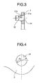
- FIG.3 is an enlarged sectional view showing the detail of the connecting part(corresponding to the part indicated by an arrow Z in FIG.2B) of a drive pin with the drive ring of the first embodiment of the invention
- FIG.4 is an enlarged front view of a through hole in the drive ring of the first embodiment.
- the inside diameter D1 of the through-hole 31 of the drive ring 3 becomes larger than the diameter D21 of the drive pin 32, a very little clearance is created between the inside periphery of the hole 31 and the outside periphery of the drive pin 32, and the solder 31b infiltrates from the tapered portion into the very little clearance.
- the present invention was made by giving attention to connecting constituent members of the variable-throat mechanism 100, to which large torque does not exert as does to a power transmitting members, reliably by means of brazing welding by a simple method.
- the drive ring 3 having through-holes and drive pins 32 among constituent members of the variable-throat mechanism 100 can be firmly connected and fixed together very easily compared to the conventional art as disclosed in patent literature 1, by putting a piece or pieces of solder on a point or points on the circumferential face of the tapered portion 31a formed at the entrance side of the through-hole 31 of the drive ring 3, the drive pins 32 are inserted into the hole 31 with an interference fit provided between the pin 32 and hole 31 at normal temperature, the integrated member of the drive ring 3 and drive pins 32 is heated in the vacuum furnace to a high temperature between 1000°C and 1100°C.
- the drive pins 32 are fitted to the holes 31 of the drive ring 3 with a piece or pieces of solder put on a point or points on the circumferential taper face provided at the entrance of each of the holes 31 for inserting each pins 32 to obtain the integrated member of the drive ring with drive pins and then the integrated member is heated in the vacuum furnace to a high temperature of 1000°C ⁇ 1100°C, the solder 31b can infiltrate into the clearance created between the inside periphery of the hole 31 and the outside periphery of the pin 32 by heating, and the solder spreads uniformly all over the clearance only by putting a piece or pieces of solder on a point or points on the circumferential face of the tapered portion 31a, as a result very firm brazing connection can be achieved.
- FIG.5 is an enlarged front view of a through hole in the drive ring showing the second embodiment of the invention.
- one or a plurality of clearance gaps 31c are provided between the inside periphery (of which the inside diameter is D2) of the through-hole 31 of the drive ring 3 and the outside periphery of the drive pin 32 by providing one or plurality of depressions on the inside periphery of the through-hole 31 for the solder to infiltrate such that the depth a 1 of the clearance gap or gaps is between 0.05 and 0.5 mm(preferably between 0.05 and 0.1 mm).
- one or a plurality of clearance gaps 31d are provided between the inside periphery(of which the inside diameter is D3) of the through-hole 31 of the drive ring 3 and the outside periphery of the drive pin 32 by providing one or plurality of semicircular groove on the inside periphery of the through-hole 31 for the solder to infiltrate such that the depth a 2 of the clearance gap or gaps is between 0.2 and 0.5 mm.
- Action and effect of the fourth embodiment is similar to those of the first embodiment.
- connection of the drive ring 3 with the drive pin 32 and the connection of the control sleeve 6 with the lever 5 are explained in the above embodiments, it is understood that invention is not limited thereto or thereby and applicable to connection of members having a through-hole or holes with a shaft member or members to be inserted into the hole or holes to be fixed therein among constituent members of variable-throat mechanism 100.
Landscapes
- Engineering & Computer Science (AREA)
- Mechanical Engineering (AREA)
- General Engineering & Computer Science (AREA)
- Chemical & Material Sciences (AREA)
- Combustion & Propulsion (AREA)
- Chemical Kinetics & Catalysis (AREA)
- General Chemical & Material Sciences (AREA)
- Supercharger (AREA)
- Control Of Turbines (AREA)
Applications Claiming Priority (1)
| Application Number | Priority Date | Filing Date | Title |
|---|---|---|---|
| JP2005022995A JP2006207526A (ja) | 2005-01-31 | 2005-01-31 | 可変容量型排気ターボ過給機及び可変ノズル機構構成部材の製造方法 |
Publications (2)
| Publication Number | Publication Date |
|---|---|
| EP1688602A1 true EP1688602A1 (de) | 2006-08-09 |
| EP1688602B1 EP1688602B1 (de) | 2007-11-07 |
Family
ID=36283984
Family Applications (1)
| Application Number | Title | Priority Date | Filing Date |
|---|---|---|---|
| EP06100978A Expired - Lifetime EP1688602B1 (de) | 2005-01-31 | 2006-01-27 | Turbolader mit verstellbarem Einlass und Verfahren zur Herstellung von Teilen dessen Verstellungsmechanismus |
Country Status (6)
| Country | Link |
|---|---|
| US (1) | US7490470B2 (de) |
| EP (1) | EP1688602B1 (de) |
| JP (1) | JP2006207526A (de) |
| KR (1) | KR100752832B1 (de) |
| CN (1) | CN100441832C (de) |
| DE (1) | DE602006000199T2 (de) |
Cited By (2)
| Publication number | Priority date | Publication date | Assignee | Title |
|---|---|---|---|---|
| EP2180159A4 (de) * | 2007-12-14 | 2015-06-03 | Mitsubishi Heavy Ind Ltd | Mechanismus für verstellbare düse |
| DE202016103778U1 (de) | 2016-07-13 | 2016-07-27 | Bosch Mahle Turbo Systems Gmbh & Co. Kg | Verstellring einer variablen Turbinengeometrie |
Families Citing this family (18)
| Publication number | Priority date | Publication date | Assignee | Title |
|---|---|---|---|---|
| JP2008095541A (ja) * | 2006-10-06 | 2008-04-24 | Toufuji Denki Kk | ターボチャージャ |
| US8491253B2 (en) * | 2008-11-03 | 2013-07-23 | Energent Corporation | Two-phase, axial flow, turbine apparatus |
| JP5012915B2 (ja) | 2010-01-15 | 2012-08-29 | トヨタ自動車株式会社 | ターボチャージャ及びそのホイールハウジング |
| JP5134717B1 (ja) | 2011-09-28 | 2013-01-30 | 三菱重工業株式会社 | 可変容量型ターボチャージャおよび可変ノズル機構の組付方法 |
| CN102528197A (zh) * | 2011-11-15 | 2012-07-04 | 北京控制工程研究所 | 一种用于双组元推力器钛合金喷注器的钎焊方法 |
| DE102012201135A1 (de) | 2012-01-26 | 2013-08-01 | Bosch Mahle Turbo Systems Gmbh & Co. Kg | Ladeeinrichtung |
| CN102562173A (zh) * | 2012-02-01 | 2012-07-11 | 大同北方天力增压技术有限公司 | 一种三维导向型气动叶片及混流涡轮联合应用的结构 |
| CN104204444B (zh) * | 2012-04-23 | 2017-06-30 | 博格华纳公司 | 具有轮廓边缘离隙的涡轮增压器叶片和结合有该涡轮增压器叶片的涡轮增压器 |
| CN104204453B (zh) | 2012-04-23 | 2019-03-08 | 博格华纳公司 | 带横向凹槽的涡轮增压器护罩以及结合有该护罩的涡轮增压器 |
| RU2014145610A (ru) | 2012-04-23 | 2016-06-10 | Боргварнер Инк. | Ступица турбины с несплошностью поверхности и турбонагнетатель, содержащий такую ступицу |
| JP5281724B1 (ja) | 2012-08-31 | 2013-09-04 | 三菱重工業株式会社 | 過給機用軸流タービン |
| US20140178188A1 (en) * | 2012-12-21 | 2014-06-26 | GM Global Technology Operations LLC | Turbo Wheel And Shaft Assembly |
| JP6163789B2 (ja) * | 2013-03-01 | 2017-07-19 | 株式会社Ihi | 可変ノズルユニット及び可変容量型過給機 |
| JP5807037B2 (ja) * | 2013-05-16 | 2015-11-10 | 株式会社豊田自動織機 | 可変ノズルターボチャージャ |
| US9500122B2 (en) | 2013-06-28 | 2016-11-22 | General Electric Company | Variable geometry nozzle and associated method of operation |
| CN107975498B (zh) | 2016-10-24 | 2021-08-31 | 开利公司 | 用于离心压缩机的扩压器及具有其的离心压缩机 |
| WO2021192414A1 (ja) * | 2020-03-24 | 2021-09-30 | 株式会社Ihi | 可変容量型過給機 |
| KR102749090B1 (ko) | 2021-11-24 | 2025-01-06 | 주식회사 성창오토텍 | 다층 여재 및 다층 구조의 케미컬 복합 필터 |
Citations (6)
| Publication number | Priority date | Publication date | Assignee | Title |
|---|---|---|---|---|
| US4659295A (en) * | 1984-04-20 | 1987-04-21 | The Garrett Corporation | Gas seal vanes of variable nozzle turbine |
| US4804316A (en) * | 1985-12-11 | 1989-02-14 | Allied-Signal Inc. | Suspension for the pivoting vane actuation mechanism of a variable nozzle turbocharger |
| EP1120546A2 (de) * | 2000-01-24 | 2001-08-01 | Mitsubishi Heavy Industries, Ltd. | Turbine mit veränderlicher Kapazität |
| EP1245307A2 (de) * | 2001-03-26 | 2002-10-02 | Mitsubishi Heavy Industries, Ltd. | Verfahren zur Herstellung eines Bauteils für eine Turbine mit veränderlichem Durchsatz |
| US20040261413A1 (en) * | 2001-11-30 | 2004-12-30 | Toshihiko Nishiyama | Variable turbocharger |
| EP1536103A1 (de) * | 2003-11-28 | 2005-06-01 | BorgWarner Inc. | Strömungsmaschine mit Leitgitter und Befestigungseinrichtung dafür |
Family Cites Families (9)
| Publication number | Priority date | Publication date | Assignee | Title |
|---|---|---|---|---|
| SU821549A2 (ru) * | 1979-05-16 | 1981-04-15 | Всесоюзный Научно-Исследователь-Ский Институт Охраны Труда Вцспс | Аэродинамический отделитель дл ВОлОКНиСТОгО МАТЕРиАлА |
| JPS5978983A (ja) | 1982-10-26 | 1984-05-08 | 日産自動車株式会社 | セラミツクスと金属との接合構造 |
| DE3722253A1 (de) * | 1987-07-06 | 1989-01-26 | Kuehnle Kopp Kausch Ag | Verstellvorrichtung eines radialverdichters |
| US5116197A (en) * | 1990-10-31 | 1992-05-26 | York International Corporation | Variable geometry diffuser |
| JPH0739032B2 (ja) | 1991-04-04 | 1995-05-01 | 昭和アルミニウム株式会社 | 金属材のろう付方法 |
| JPH07236968A (ja) | 1994-02-28 | 1995-09-12 | Mitsubishi Electric Corp | 溝付き管のろう付方法及び溝付き管のろう付け構造 |
| JP2758135B2 (ja) | 1994-05-19 | 1998-05-28 | 本田技研工業株式会社 | 半田付け接合方法 |
| JP2002038967A (ja) * | 2000-07-27 | 2002-02-06 | Toyota Motor Corp | 可変ノズル式ターボチャージャ |
| DE10209484B4 (de) * | 2002-03-05 | 2004-06-24 | Borgwarner Turbo Systems Gmbh | Turbolader für Fahrzeuge mit verbesserter Aufhängung für den Betätigungsmechanismus der variablen Düsen |
-
2005
- 2005-01-31 JP JP2005022995A patent/JP2006207526A/ja active Pending
-
2006
- 2006-01-04 US US11/324,258 patent/US7490470B2/en not_active Expired - Lifetime
- 2006-01-18 CN CNB2006100050398A patent/CN100441832C/zh not_active Expired - Fee Related
- 2006-01-27 EP EP06100978A patent/EP1688602B1/de not_active Expired - Lifetime
- 2006-01-27 KR KR1020060008604A patent/KR100752832B1/ko not_active Expired - Fee Related
- 2006-01-27 DE DE602006000199T patent/DE602006000199T2/de not_active Expired - Lifetime
Patent Citations (6)
| Publication number | Priority date | Publication date | Assignee | Title |
|---|---|---|---|---|
| US4659295A (en) * | 1984-04-20 | 1987-04-21 | The Garrett Corporation | Gas seal vanes of variable nozzle turbine |
| US4804316A (en) * | 1985-12-11 | 1989-02-14 | Allied-Signal Inc. | Suspension for the pivoting vane actuation mechanism of a variable nozzle turbocharger |
| EP1120546A2 (de) * | 2000-01-24 | 2001-08-01 | Mitsubishi Heavy Industries, Ltd. | Turbine mit veränderlicher Kapazität |
| EP1245307A2 (de) * | 2001-03-26 | 2002-10-02 | Mitsubishi Heavy Industries, Ltd. | Verfahren zur Herstellung eines Bauteils für eine Turbine mit veränderlichem Durchsatz |
| US20040261413A1 (en) * | 2001-11-30 | 2004-12-30 | Toshihiko Nishiyama | Variable turbocharger |
| EP1536103A1 (de) * | 2003-11-28 | 2005-06-01 | BorgWarner Inc. | Strömungsmaschine mit Leitgitter und Befestigungseinrichtung dafür |
Cited By (3)
| Publication number | Priority date | Publication date | Assignee | Title |
|---|---|---|---|---|
| EP2180159A4 (de) * | 2007-12-14 | 2015-06-03 | Mitsubishi Heavy Ind Ltd | Mechanismus für verstellbare düse |
| DE202016103778U1 (de) | 2016-07-13 | 2016-07-27 | Bosch Mahle Turbo Systems Gmbh & Co. Kg | Verstellring einer variablen Turbinengeometrie |
| US10633999B2 (en) | 2016-07-13 | 2020-04-28 | BMTS Technology GmbH & Co. KG | Adjustment ring of a variable turbine geometry |
Also Published As
| Publication number | Publication date |
|---|---|
| EP1688602B1 (de) | 2007-11-07 |
| US7490470B2 (en) | 2009-02-17 |
| KR100752832B1 (ko) | 2007-08-29 |
| KR20060088042A (ko) | 2006-08-03 |
| DE602006000199D1 (de) | 2007-12-20 |
| CN100441832C (zh) | 2008-12-10 |
| US20060168959A1 (en) | 2006-08-03 |
| CN1821552A (zh) | 2006-08-23 |
| DE602006000199T2 (de) | 2008-08-28 |
| JP2006207526A (ja) | 2006-08-10 |
Similar Documents
| Publication | Publication Date | Title |
|---|---|---|
| EP1688602B1 (de) | Turbolader mit verstellbarem Einlass und Verfahren zur Herstellung von Teilen dessen Verstellungsmechanismus | |
| US7364401B2 (en) | Method for manufacturing variable-throat exhaust turbocharger and constituent members of variable throat-area mechanism | |
| US20100047072A1 (en) | Turbocharger | |
| CN101529063B (zh) | 涡轮机隔热屏组件 | |
| KR100382090B1 (ko) | 가변용량 터빈의 가변 노즐기구 | |
| EP2337929B1 (de) | Lüftung einer hochdruckturbine in einer turbomaschine | |
| US4749334A (en) | Ceramic rotor-shaft attachment | |
| CA2598379C (en) | Oil bearing and tube assembly concept | |
| CN103261716A (zh) | 用于涡轮增压机的轴承装置和涡轮增压机 | |
| JP2007231934A (ja) | 可変ノズル付きターボチャージャ | |
| CN1948718B (zh) | 涡轮覆环组合件及组装燃气涡轮发动机的方法 | |
| EP2412940B1 (de) | Drehbare Komponentenfassung für einen Gasturbinenmotor | |
| US9234459B2 (en) | Turbocharger and wheel housing | |
| US20100111692A1 (en) | Exhaust gas turbocharger for a motor vehicle | |
| US11326514B2 (en) | Variable capacity turbocharger | |
| EP1609950A2 (de) | Schaufeleinsatz mit einem gezackten Rand | |
| JPWO2020031262A1 (ja) | タービンシャフト、過給機及び過給機の製造方法 | |
| GB2436130A (en) | Stator vane arrangement with anti-bonding layer | |
| JPH03213601A (ja) | 組立型タービン動翼 |
Legal Events
| Date | Code | Title | Description |
|---|---|---|---|
| PUAI | Public reference made under article 153(3) epc to a published international application that has entered the european phase |
Free format text: ORIGINAL CODE: 0009012 |
|
| AK | Designated contracting states |
Kind code of ref document: A1 Designated state(s): AT BE BG CH CY CZ DE DK EE ES FI FR GB GR HU IE IS IT LI LT LU LV MC NL PL PT RO SE SI SK TR |
|
| AX | Request for extension of the european patent |
Extension state: AL BA HR MK YU |
|
| 17P | Request for examination filed |
Effective date: 20061110 |
|
| 17Q | First examination report despatched |
Effective date: 20061214 |
|
| AKX | Designation fees paid |
Designated state(s): DE FR GB NL |
|
| GRAP | Despatch of communication of intention to grant a patent |
Free format text: ORIGINAL CODE: EPIDOSNIGR1 |
|
| GRAS | Grant fee paid |
Free format text: ORIGINAL CODE: EPIDOSNIGR3 |
|
| GRAA | (expected) grant |
Free format text: ORIGINAL CODE: 0009210 |
|
| AK | Designated contracting states |
Kind code of ref document: B1 Designated state(s): DE FR GB NL |
|
| REG | Reference to a national code |
Ref country code: GB Ref legal event code: FG4D |
|
| REF | Corresponds to: |
Ref document number: 602006000199 Country of ref document: DE Date of ref document: 20071220 Kind code of ref document: P |
|
| ET | Fr: translation filed | ||
| PLBE | No opposition filed within time limit |
Free format text: ORIGINAL CODE: 0009261 |
|
| STAA | Information on the status of an ep patent application or granted ep patent |
Free format text: STATUS: NO OPPOSITION FILED WITHIN TIME LIMIT |
|
| 26N | No opposition filed |
Effective date: 20080808 |
|
| REG | Reference to a national code |
Ref country code: NL Ref legal event code: V1 Effective date: 20110801 |
|
| PG25 | Lapsed in a contracting state [announced via postgrant information from national office to epo] |
Ref country code: NL Free format text: LAPSE BECAUSE OF NON-PAYMENT OF DUE FEES Effective date: 20110801 |
|
| PGFP | Annual fee paid to national office [announced via postgrant information from national office to epo] |
Ref country code: NL Payment date: 20100131 Year of fee payment: 5 |
|
| REG | Reference to a national code |
Ref country code: FR Ref legal event code: PLFP Year of fee payment: 11 |
|
| REG | Reference to a national code |
Ref country code: FR Ref legal event code: PLFP Year of fee payment: 12 |
|
| REG | Reference to a national code |
Ref country code: FR Ref legal event code: PLFP Year of fee payment: 13 |
|
| REG | Reference to a national code |
Ref country code: DE Ref legal event code: R082 Ref document number: 602006000199 Country of ref document: DE Representative=s name: CBDL PATENTANWAELTE, DE Ref country code: DE Ref legal event code: R081 Ref document number: 602006000199 Country of ref document: DE Owner name: MITSUBISHI HEAVY INDUSTRIES ENGINE & TURBOCHAR, JP Free format text: FORMER OWNER: MITSUBISHI HEAVY INDUSTRIES, LTD., TOKYO, JP |
|
| REG | Reference to a national code |
Ref country code: GB Ref legal event code: 732E Free format text: REGISTERED BETWEEN 20180913 AND 20180919 |
|
| PGFP | Annual fee paid to national office [announced via postgrant information from national office to epo] |
Ref country code: FR Payment date: 20201210 Year of fee payment: 16 |
|
| PGFP | Annual fee paid to national office [announced via postgrant information from national office to epo] |
Ref country code: GB Payment date: 20210120 Year of fee payment: 16 |
|
| GBPC | Gb: european patent ceased through non-payment of renewal fee |
Effective date: 20220127 |
|
| PG25 | Lapsed in a contracting state [announced via postgrant information from national office to epo] |
Ref country code: GB Free format text: LAPSE BECAUSE OF NON-PAYMENT OF DUE FEES Effective date: 20220127 |
|
| PG25 | Lapsed in a contracting state [announced via postgrant information from national office to epo] |
Ref country code: FR Free format text: LAPSE BECAUSE OF NON-PAYMENT OF DUE FEES Effective date: 20220131 |
|
| REG | Reference to a national code |
Ref country code: DE Ref legal event code: R082 Ref document number: 602006000199 Country of ref document: DE Representative=s name: CBDL PATENTANWAELTE GBR, DE |
|
| PGFP | Annual fee paid to national office [announced via postgrant information from national office to epo] |
Ref country code: DE Payment date: 20221130 Year of fee payment: 18 |
|
| REG | Reference to a national code |
Ref country code: DE Ref legal event code: R119 Ref document number: 602006000199 Country of ref document: DE |
|
| PG25 | Lapsed in a contracting state [announced via postgrant information from national office to epo] |
Ref country code: DE Free format text: LAPSE BECAUSE OF NON-PAYMENT OF DUE FEES Effective date: 20240801 |
|
| PG25 | Lapsed in a contracting state [announced via postgrant information from national office to epo] |
Ref country code: DE Free format text: LAPSE BECAUSE OF NON-PAYMENT OF DUE FEES Effective date: 20240801 |