EP1688632B1 - Kreuzgelenk mit verbesserter Schmierung - Google Patents
Kreuzgelenk mit verbesserter Schmierung Download PDFInfo
- Publication number
- EP1688632B1 EP1688632B1 EP06001834A EP06001834A EP1688632B1 EP 1688632 B1 EP1688632 B1 EP 1688632B1 EP 06001834 A EP06001834 A EP 06001834A EP 06001834 A EP06001834 A EP 06001834A EP 1688632 B1 EP1688632 B1 EP 1688632B1
- Authority
- EP
- European Patent Office
- Prior art keywords
- ball
- universal joint
- cavity
- seal
- plate
- Prior art date
- Legal status (The legal status is an assumption and is not a legal conclusion. Google has not performed a legal analysis and makes no representation as to the accuracy of the status listed.)
- Expired - Lifetime
Links
Images


Classifications
-
- F—MECHANICAL ENGINEERING; LIGHTING; HEATING; WEAPONS; BLASTING
- F16—ENGINEERING ELEMENTS AND UNITS; GENERAL MEASURES FOR PRODUCING AND MAINTAINING EFFECTIVE FUNCTIONING OF MACHINES OR INSTALLATIONS; THERMAL INSULATION IN GENERAL
- F16D—COUPLINGS FOR TRANSMITTING ROTATION; CLUTCHES; BRAKES
- F16D3/00—Yielding couplings, i.e. with means permitting movement between the connected parts during the drive
- F16D3/16—Universal joints in which flexibility is produced by means of pivots or sliding or rolling connecting parts
- F16D3/26—Hooke's joints or other joints with an equivalent intermediate member to which each coupling part is pivotally or slidably connected
- F16D3/36—Hooke's joints or other joints with an equivalent intermediate member to which each coupling part is pivotally or slidably connected in which each pivot between the coupling parts and the intermediate member comprises a single ball
-
- F—MECHANICAL ENGINEERING; LIGHTING; HEATING; WEAPONS; BLASTING
- F16—ENGINEERING ELEMENTS AND UNITS; GENERAL MEASURES FOR PRODUCING AND MAINTAINING EFFECTIVE FUNCTIONING OF MACHINES OR INSTALLATIONS; THERMAL INSULATION IN GENERAL
- F16D—COUPLINGS FOR TRANSMITTING ROTATION; CLUTCHES; BRAKES
- F16D3/00—Yielding couplings, i.e. with means permitting movement between the connected parts during the drive
- F16D3/16—Universal joints in which flexibility is produced by means of pivots or sliding or rolling connecting parts
- F16D3/26—Hooke's joints or other joints with an equivalent intermediate member to which each coupling part is pivotally or slidably connected
- F16D3/30—Hooke's joints or other joints with an equivalent intermediate member to which each coupling part is pivotally or slidably connected in which the coupling is specially adapted to constant velocity-ratio
- F16D3/32—Hooke's joints or other joints with an equivalent intermediate member to which each coupling part is pivotally or slidably connected in which the coupling is specially adapted to constant velocity-ratio by the provision of two intermediate members each having two relatively perpendicular trunnions or bearings
-
- F—MECHANICAL ENGINEERING; LIGHTING; HEATING; WEAPONS; BLASTING
- F16—ENGINEERING ELEMENTS AND UNITS; GENERAL MEASURES FOR PRODUCING AND MAINTAINING EFFECTIVE FUNCTIONING OF MACHINES OR INSTALLATIONS; THERMAL INSULATION IN GENERAL
- F16D—COUPLINGS FOR TRANSMITTING ROTATION; CLUTCHES; BRAKES
- F16D3/00—Yielding couplings, i.e. with means permitting movement between the connected parts during the drive
- F16D3/84—Shrouds, e.g. casings, covers; Sealing means specially adapted therefor
- F16D3/843—Shrouds, e.g. casings, covers; Sealing means specially adapted therefor enclosed covers
- F16D3/848—Shrouds, e.g. casings, covers; Sealing means specially adapted therefor enclosed covers allowing relative movement of joint parts due to sliding between parts of the cover
-
- Y—GENERAL TAGGING OF NEW TECHNOLOGICAL DEVELOPMENTS; GENERAL TAGGING OF CROSS-SECTIONAL TECHNOLOGIES SPANNING OVER SEVERAL SECTIONS OF THE IPC; TECHNICAL SUBJECTS COVERED BY FORMER USPC CROSS-REFERENCE ART COLLECTIONS [XRACs] AND DIGESTS
- Y10—TECHNICAL SUBJECTS COVERED BY FORMER USPC
- Y10T—TECHNICAL SUBJECTS COVERED BY FORMER US CLASSIFICATION
- Y10T403/00—Joints and connections
- Y10T403/32—Articulated members
- Y10T403/32606—Pivoted
- Y10T403/32631—Universal ball and socket
Definitions
- This invention relates to improving lubrication in a universal joint, particularly in a double cardan universal joint.
- a universal joint having a double-cross link is known from EP-A-0469396 A1 .
- a constant velocity joint having a centering disk bearing eccentric socket is known from US 5,419,740 .
- a centering apparatus for constant velocity universal joint is known from US 4,650,439 .
- the invention in one aspect provides an elastomeric seal for a ball and socket centering apparatus of a universal joint.
- an elastomeric seal is bonded to a metal or other rigid strong material ball retainer ring that has an internal spherical surface in sliding contact with the external spherical surface of a centering ball of the universal joint.
- the elastomeric seal is bonded at an outer end of the ball retainer so as to wipe against a spherical surface of the ball as the ball rotates relative to the ball retainer. The seal wipes against the ball as the ball rotates relative to the retainer to retain lubricant in the socket in which the ball is received.
- the seal in a free state extends radially inward relative to the retainer, beyond the spherical surface of the retainer so that when, if placed in mating contact with the retainer, the ball compresses the seal radially outward, so that the seal presses against the spherical surface of the ball with sufficient force to retain the lubricant in the socket.
- the retainer spherical surface is shaped such that it interferes with withdrawal of the ball from the socket.
- the seal is not subjected to the significant forces that act on the ball to withdraw it from the socket, but those are borne by the retainer which is made of a rigid material such as steel or another strong or rigid material.
- a seal of the invention helps retain lubricant in the ball socket and helps keep dirt out of the socket and away from the ball retainer.
- the seal follows the contour of the outside of the ball as the drive line that includes the universal joint is angled. This feature decreases the need to lubricate the ball socket area more often and extends the mechanical life of the ball and socket.
- the invention provides a universal joint housing that contains lubricant to lubricate a moving center plate and floating wear plates. Over a period of time, a housing of a constant velocity universal joint needs to be re-lubricated because the lubrication pumps out of the housing as the center plate moves to the outer edge of the lubricated cavity in the housing as the housing rotates.
- the invention seeks to increase the length of the lubrication period and decrease the wear generated in the sliding area of the housing by adding cavity plates on each face of the housing that also act as wear plates. Each cavity plate acts like a labyrinth mechanical seal as it captures the lubricant behind it in a reservoir groove in the housing.
- the reservoir replenishes the moving surfaces with lubrication in an extended period of time, decreasing the frequency of the need for lubrication.
- the pumping action of lubricant still takes place but the lubricant is captured in the reservoir behind the cavity plate, keeping the lubricant available longer as the lubricant in the cavity is used up.
- the material of the cavity plate also acts as an enlarged wear area (enlarged relative to if it was not present) and therefore should be chosen to be strong and wear resistant.
- Some materials that may be used for these plates include spring steel, nylon and other wear resistant plastics and metals.
- seals can be provided between the retainer and the ball socket, between the centering plate and the wear plates and between the wear plates and the cavity plates.
- One or more lubrication passageways can be provided in the centering plate that communicate with the ball sockets through an orifice so as to regulate lubricant flow between the center cavity and the ball sockets.
- Fig. 1 is a cross-sectional view of a double cardan universal joint incorporating aspects of the invention
- Fig. 2 is a cross-sectional view like Fig. 1 illustrating the universal joint of Fig. 1 at an extreme angle;
- Fig. 3 is a detail view of the right-hand ball socket area of the universal joint of Fig. 2 , the left-hand ball socket area being a mirror image of Fig. 3 ;
- Fig. 4 is a partial section view of the ball retainer seal illustrated in Figs. 1-3 ;
- Fig. 5 is a detail view of the upper portion of Fig. 4 ;
- Fig. 6 is a axial plan view of one of the cavity plates illustrated in Figs. 1 and 2 .
- Fig. 7 is a view similar to Fig. 1 of a second embodiment of the invention.
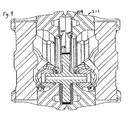
- Fig. 8 is a view similar to Fig. 3 of the embodiment of Fig. 7 ;
- Fig. 9 is a view similar to Fig. 2 of a third embodiment of the invention.
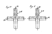
- Fig. 10 is a partial cross-sectional view of an alternative centering plate for the three embodiments illustrated.
- Fig. 11 is a view like Fig. 10 but of another alternative centering plate.
- a double Hooke's type universal joint 10 has a housing 12 and a pair of yokes 14 connected to the housing 12 by a pair of respective cross links 16 in well known manner.
- Each yoke 14 defines at its inner end a ball socket 18 ( Fig. 3 ) in which is received a ball 20 having an external spherical surface 22 and an internal cylindrical surface 24 in which is slidibly received a pin 26 of a centering plate 28 that slides in a center cavity 29 of the housing 12.
- the spherical surface 22 of the ball 20 mates with the internal spherical surface 29 of the ball cavity 18 and also mates with an internal spherical surface 30 of a ball retainer 32.
- the surface 30 captures the ball 20 in the ball socket 18 as it is made of steel or another rigid material that fixes the ball 20 in the socket 18 while permitting sliding movement of the spherical surface 22 against the spherical surfaces 30 and 28.
- the ball retainer 32 is held in the inner end of the yoke 14 by a snap ring 34 that fits in an external groove of the retainer 32 and fits in an internal groove in the end of the yoke 14.
- the hard and rigid part of the retainer 32 is referred to as the body portion 36 of the retainer 32 and the seal portion 40 is referred to as such herein.
- the seal portion 40 is bonded in a recess at the exterior end of the body portion 36 and has a generally U-shaped cross-section as illustrated in Figs. 4 and 5 .
- the seal 40 is made of an elasotmeric material such as a natural or synthetic rubber. One common material for the seal found suitable is black viton.
- the body portion 36 of the retainer 32 is a relatively hard and rigid material such as steel, as it bears most of the load that retains the ball 20 in the ball socket 18.
- the seal 40 has an outer leg portion 42, a connecting bridge portion 44 and an inner leg portion 46 extending from the inner end of the connecting portion 44.
- the outer portion 42 and the bridge 44 are bonded to the recessed surface 48 at the outer axial end of the body portion 36 of the retainer 32.
- the inner leg portion has a curved inner surface 50 that is shaped to conform to the spherical surface 22 of the ball 20 and that, in its free state, is radially inward of the surface 30 of the body portion 36.
- the ball presses the surface 50 and the inner leg portion 46 radially outwardly with a force such that the coating of lubricant on the surface 22 of the ball 20 is wiped backwardly toward the ball recess 18 by edge 52 of the seal 40 so as to keep the lubricant largely inside of the edge 52.
- the opposite or outer end of surface 50, at 54 (its outer edge) is curved so as not to scrape or wipe lubricant on the surface 22 outwardly when the ball surface 22 retreats inwardly past the end 54. Thereby, lubricant on the surface 22 is impeded from going outside of the ball recess 18 past edge 52, and the reentry of the lubricant film on the surface 22 is facilitated by the shape of the end 54.
- the inner leg 46 can resiliently deflect outward as shown at 60 in Fig. 3 when it comes into contact with the pin 26.
- the seal 40 can spring back to its normal position, shown at the opposite side of the seal in Fig. 3 .
- the seal 40 can spring back to the position shown in Fig. 5 .
- the universal joint 12 has a pair of cavity plates 62 which are annular in shape as shown in Fig. 6 .
- the cavity plates 62 are received in recesses formed in the housing 12, one on each side of the centering plate 28, so that they form surfaces against which wear plates 64 slide.
- the cavity plates 62 partially close off the open end of the lubrication reservoirs 66 that are formed in each half of the housing 12. By closing these openings of the reservoirs 66 off, the cavity plates 62 impede the escape of lubricant from the reservoirs 66.
- the cavity plates 62 enlarge the area of the wear surfaces of the cavity 29 defined by the housing 12 in which the centering plate 28 and wear plates 64 are received and orbit, they reduce wear of the wear plates 64. In addition they make it less likely that the centering disc 28 or wear plates 64 will tip relative to the housing 12 in the cavity 29 in which the centering plate 28 and wear plates 64 orbit.
- the cavity plate 62 should be made of a dimensionally stable material that presents a good wear surface, such as steel, nylon or a similar material. For example, one material found suitable is spring steel.
- the cavity plates 62 are received in grooves, one formed in each housing half (the housing halves are bolted together to form the housing 12) and are kept in these grooves by the centering plate 28 and wear plates 64 holding the cavity plates 62 spaced apart.
- the cavity plates 62 could be bonded or otherwise secured to each housing half.
- Figs. 7 and 8 illustrate a second embodiment 110 that is very similar to the first embodiment 10.
- elements corresponding to elements of the first embodiment 10 are labeled with the same reference number plus 100.
- the embodiment 110 differs from the embodiment 10 in that it has an additional seal 172 between the ball retainer 132 and the ball cavity 118, to help retain lubricant in the ball cavity, and has an additional seal 174 on each face of the centering plate 128, at each circumferential corner as illustrated in Fig. 7 .
- a seal 178 is also provided at the inner diameter of each plate 162 and is bonded thereto to create a sliding seal with the adjacent plate 164
- the seals 174 and 178 help retain lubricant in the center cavity 29 area of the housing 112.
- the seals 172 and 174 could be provided as o-ring seals as illustrated, or could be provided as bonded-on lip seals like the seal 40.
- FIG. 9 A third embodiment 210 having additional seals is illustrated in Fig. 9 .
- elements corresponding to elements of the second embodiment 110 are labeled with the same reference number plus 100.
- the embodiment 210 differs from the embodiment 110 by having an alternative for the seal 174, which is a band seal 276 provided around the outside circumference of the centering plate 28 as illustrated in Fig. 9 .
- the edges of the seal 276 create a sliding seal with the plates 264 that helps retain lubricant in the center cavity 229 of the housing 212.
- Seals 172 are not illustrated in this embodiment, but could be.
- Figs. 10 and 11 illustrate alternative lubrication passageways 79 and 80 running radially through the centering plate 28 that communicate with axial passageway 82 of embodiment 10. Only one is shown in each centering plate although more than one may be provided.
- the passageway 82 runs through the plate 28 and pins 26 to provide communication between the ball sockets 18, and the passageway 79 or 80 provides communication from the center cavity 29 of the housing to the passageway 82, and therefore to the ball sockets 18.
- Fig. 10 illustrates the passageway 79 made using a center drill and
- Fig. 11 illustrates the passageway 80 made using a standard drill bit and controlling the drill point break-through depth.
- Both passageways 79 and 80 have a smaller diameter hole at its inner end that acts as an orifice to regulate the flow of grease passing between the center cavity grease reservoir and the two ball sockets. This smaller diameter hole creates resistance to flow and therefore creates a pressure difference when filling with grease and when running.
- the passageways 79 or 80 can be applied to any of the embodiments of the invention.
Landscapes
- Engineering & Computer Science (AREA)
- General Engineering & Computer Science (AREA)
- Mechanical Engineering (AREA)
- Pivots And Pivotal Connections (AREA)
- Sealing Devices (AREA)
Claims (23)
- Ein Kreuzgelenk (10) der Art, die ein Paar Joche (14) hat, die drehbar miteinander mit einer Zentrierungsvorrichtung (28) zwischen den Jochen (14) verbunden sind, mit wenigstens einer Kugel (20), die in eine Kugelschale (18) aufgenommen ist, wobei die Kugel (20) in der Kugelschale (18) von einem Kugelkäfig (32) gehalten ist, der aufweist:(a) einen Käfigkörper (36), der starr ist und die Kugel (20) axial in der Schale (18) hält; und(b) eine gummiartige Dichtung (40), die an einer axialen Endfläche des Käfigkörpers (36) haftet, um gegen einer kugelförmigen Fläche (22) der Kugel (20) zu schleifen, wenn sich die Kugel (20) relativ zu dem Kugelkäfig (32) dreht,dadurch gekennzeichnet,
dass der Käfigkörper (32) axial an einem der Joche (14) befestigt ist und die Kugel (20) axial in der Schale (18) relativ zu einem der Joche (14) hält, und wobei die gummiartige Dichtung (40) axial relativ zu einer der Joche (14) fixiert ist. - Das Kreuzgelenk nach Anspruch 1
wobei die Dichtung (40) in eine Aussparung in einer Endfläche des Käfigkörpers (36) aufgenommen ist. - Das Kreuzgelenk nach Anspruch 1,
wobei eine kugelförmige Fläche (30) an dem Käfigkörper (32) geformt ist, die zu einer kugelförmigen Fläche (22) der Kugel (20) passt, und wobei eine kugelförmige Fläche an der Dichtung (40) geformt ist, die zu der kugelförmigen Fläche (22) der Kugel (20) passt. - Das Kreuzgelenk nach Anspruch 1,
wobei in einem freien Zustand die Dichtung (40) sich weiter radial nach innen erstreckt als der Käfigkörper (36). - Das Kreuzgelenk nach Anspruch 1,
wobei die Dichtung (40) einen U-förmigen Querschnitt hat. - Das Kreuzgelenk nach Anspruch 1,
wobei die Dichtung einen inneren Arm (36) hat, der sich radial von dem Käfigkörper (36) einwärts erstreckt. - Das Kreuzgelenk nach Anspruch 1,
wobei die Dichtung (40) einen inneren Arm (46) hat, der sich axial von dem Käfigkörper und radial einwärts von dem Käfigkörper (36) erstreckt. - Das Kreuzgelenk nach Anspruch 1,
wobei in einer extremen Position des Kreuzgelenks (10) die Dichtung (40) einen weichen Stop vorsieht, der eine weitere Verwinkelung des Kreuzgelenks (10) begrenzt. - Das Kreuzgelenk nach Anspruch 1,
wobei die Dichtung (40) eine Kante (52) hat, die Schmiermittel auf der kugelförmigen Fläche (22) der Kugel (20) rückwärts bezüglich der Kugel zurück in die Kugelschale (18) abstreift, wenn sich die Kugel (20) aus der Dichtung (40) dreht. - Das Kreuzgelenk nach Anspruch 1,
wobei die Kugel (20) den Durchmesser der gummiartigen Dichtung (40) aufweitet, wenn der Käfig (32) mit der Kugel (20) zusammengesetzt wird. - Das Kreuzgelenk nach Anspruch 1,
wobei die Dichtung (40) einen gerundeten äußeren Rand hat. - Das Kreuzgelenk nach Anspruch 1,
ferner enthaltend eine Dichtung (172) zwischen dem Käfigkörper und der Kugelschale. - Ein doppeltes Kreuzgelenk (10) mit einem Paar Joche, die drehbar miteinander durch ein Gehäuse (12) und eine Zentrierungsvorrichtung zwischen den Jochen verbunden sind, mit einer Zentrierungsplatte (28), die in einen Hohlraum (29) des Gehäuses (12) aufgenommen ist, wobei die Flächen des Hohlraums wenigstens teilweise durch axial sich erstreckende Aussparungen begrenzt sind, wobei wenigstens eine Hohlraumplatte (62) in den Hohlraum (66) aufgenommen ist, die axial und radial relativ zu dem Gehäuse (12) fixiert ist, derart, dass die Hohlraumplatte (32) wenigstens teilweise wenigstens eine der sich axial erstreckenden Aussparungen (36) verschließt.
- Das doppelte Kreuzgelenk nach Anspruch 13,
wobei die Hohlraumplatte ringförmig ist. - Das doppelte Kreuzgelenk nach Anspruch 13,
wobei zwei Hohlraumplatten (62) vorgesehen sind und jede Hohlraumplatte (62) teilweise wenigstens eine axial sich erstreckende Aussparung verschließt, eine an jeder Seite der Zentrierungsplatte (28). - Das doppelte Kreuzgelenk nach Anspruch 13,
wobei eine axial einwärts weisende Fläche der Hohlraumplatte (62) eine vergrößerte Abnutzungsfläche vorsieht. - Das doppelte Kreuzgelenk nach Anspruch 13,
wobei wenigstens eine Abnutzungsplatte (64) zwischen der Hohlraumplatte (62) und der wenigstens einen Zentrierungsplatte (28) vorgesehen ist und die Abnutzungsplatte (64) gegen eine axial weisende Fläche der Zentrierungsplatte (28) gleitet und gegen eine axial weisende Fläche der wenigstens einen Hohlraumplatte (62) gleitet. - Das doppelte Kreuzgelenk nach Anspruch 17,
wobei wenigstens eine gummiartige Dichtung zwischen der Zentrierungsplatte und der wenigstens einen Abnutzungsplatte vorgesehen ist. - Das doppelte Kreuzgelenk nach Anspruch 17,
wobei wenigstens eine gummiartige Dichtung zwischen der wenigstens einen Abnutzungsplatte und der wenigstens einen Hohlraumplatte vorgesehen ist. - Das doppelte Kreuzgelenk nach Anspruch 13,
wobei die Hohlraumplatte in eine Aussparung des Hohlraums aufgenommen ist, in dem die Zentrierungsplatte umläuft. - Das doppelte Kreuzgelenk nach Anspruch 13,
wobei ein Paar Hohlraumplatten (62) in der Aussparung (66) vorgesehen ist, eine an jeder Seite der Zentrierungsplatte (28), und wobei die Hohlraumplatten (62) axial und radial so fixiert sind, dass sie teilweise eine Öffnung in eine axial sich erstreckende Schmiermittelreservoiraussparung (66) verschließen. - Ein doppeltes Kreuzgelenk nach jedem der vorhergehenden Ansprüche, mit einem Paar Joche, die drehbar miteinander durch ein Gehäuse und eine Zentrierungsvorrichtung zwischen den Jochen verbunden sind, mit einer Zentrierungsplatte, die in einen Hohlraum des Gehäuses aufgenommen ist, wobei jedes Joch eine Kugelschale hat, die mit der Zentrierungsplatte verbunden ist, wobei die Zentrierungsplatte Durchgangsbahnen hat, die die Kugelschalen mit dem Hohlraum des Gehäuses durch wenigstens einen Auslass verbinden, der den Schmiermittelstrom von dem Hohlraum zu den Kugelschalen beschränkt.
- Das doppelte Kreuzgelenk nach Anspruch 22,
wobei die Durchgangsbahnen wenigstens eine radial sich erstreckende Durchgangsbahn enthalten, die an einem inneren Ende mit dem Auslass in der Verbindung steht.
Applications Claiming Priority (1)
| Application Number | Priority Date | Filing Date | Title |
|---|---|---|---|
| US11/051,912 US7235016B2 (en) | 2005-02-04 | 2005-02-04 | Universal joint lubrication |
Publications (3)
| Publication Number | Publication Date |
|---|---|
| EP1688632A2 EP1688632A2 (de) | 2006-08-09 |
| EP1688632A3 EP1688632A3 (de) | 2007-03-28 |
| EP1688632B1 true EP1688632B1 (de) | 2010-12-15 |
Family
ID=35911121
Family Applications (1)
| Application Number | Title | Priority Date | Filing Date |
|---|---|---|---|
| EP06001834A Expired - Lifetime EP1688632B1 (de) | 2005-02-04 | 2006-01-30 | Kreuzgelenk mit verbesserter Schmierung |
Country Status (5)
| Country | Link |
|---|---|
| US (2) | US7235016B2 (de) |
| EP (1) | EP1688632B1 (de) |
| AT (1) | ATE491894T1 (de) |
| CA (1) | CA2535250C (de) |
| DE (1) | DE602006018810D1 (de) |
Families Citing this family (7)
| Publication number | Priority date | Publication date | Assignee | Title |
|---|---|---|---|---|
| JP5063280B2 (ja) * | 2007-09-28 | 2012-10-31 | 株式会社日立製作所 | ファイル転送システム、クライアント、サーバ |
| IT201800009788A1 (it) * | 2018-10-25 | 2020-04-25 | Edi Bondioli | Giunto omocinetico grandangolare con serbatoio di lubrificante |
| CN112363427B (zh) * | 2020-10-28 | 2021-08-31 | 浙江树人学院(浙江树人大学) | 一种工业机器人用伺服电机驱动控制系统 |
| CN112196911B (zh) * | 2020-11-09 | 2023-07-21 | 中国船舶重工集团公司第七0三研究所 | 一种用于高速齿轮式联轴器润滑装置 |
| CN112524167B (zh) * | 2020-12-22 | 2021-10-15 | 泰尔重工股份有限公司 | 一种具有轴向大伸缩功能的鼓型齿联轴器 |
| WO2022135801A1 (en) * | 2020-12-22 | 2022-06-30 | Comer Industries S.P.A. | Wide-angle constant-velocity joint with optimized lubrication |
| CN114412915B (zh) * | 2022-03-30 | 2022-06-07 | 达州市卡雷亚数控机床有限公司 | 一种具有轴承和轴的传动装置 |
Family Cites Families (28)
| Publication number | Priority date | Publication date | Assignee | Title |
|---|---|---|---|---|
| US1911214A (en) * | 1928-08-22 | 1933-05-30 | Manning & Co | Universal joint |
| US1987807A (en) * | 1929-08-14 | 1935-01-15 | Mechanics Universal Joint Comp | Universal joint assembly |
| US2991634A (en) * | 1960-07-29 | 1961-07-11 | Gen Motors Corp | Universal joint centering device |
| US3120746A (en) * | 1962-01-22 | 1964-02-11 | Dana Corp | Pressure equalizing means for a double cardan joint centering device |
| US3848938A (en) * | 1973-02-28 | 1974-11-19 | Torrington Co | Bearing and bearing seal |
| US3947077A (en) * | 1973-04-18 | 1976-03-30 | Caterpillar Tractor Co. | Sealed ball and socket connection |
| DE2802572C2 (de) * | 1978-01-21 | 1982-07-22 | Jean Walterscheid Gmbh, 5204 Lohmar | Homokinetisches Doppelgelenk für große Beugewinkel |
| DE2833149C2 (de) * | 1978-07-28 | 1980-08-28 | Gelenkwellenbau Gmbh, 4300 Essen | Doppelkardangelenk |
| FR2456875A1 (fr) * | 1979-05-15 | 1980-12-12 | Dba | Articulation a rotule |
| DE3138190C2 (de) * | 1981-09-25 | 1983-08-11 | Jean Walterscheid Gmbh, 5204 Lohmar | Abschmierbares Weitwinkelgelenk |
| DE3142930C2 (de) * | 1981-10-29 | 1983-08-25 | Jean Walterscheid Gmbh, 5204 Lohmar | Abschmierbares Weitwinkelgelenk |
| US4650439A (en) * | 1984-12-10 | 1987-03-17 | Weasler Engineering, Inc. | Centering apparatus for constant velocity universal joint |
| US4781662A (en) * | 1985-11-14 | 1988-11-01 | Weasler Engineering, Inc. | Universal joint with improved lubrication |
| DE8536143U1 (de) * | 1985-12-21 | 1986-02-20 | SKF Gleitlager GmbH, 6625 Püttlingen | Anordnung zur Abdichtung von Lagern, insbesondere von Gelenklagern mit aus zwei Halbschalen zusammengesetztem Außenring |
| DE3636194C1 (de) | 1986-10-24 | 1988-06-30 | Walterscheid Gmbh Jean | Homokinetisches Doppelgelenk |
| DE8705293U1 (de) * | 1987-04-09 | 1987-07-09 | SKF Gleitlager GmbH, 6625 Püttlingen | Vorrichtung zur Abdichtung von Lagern, insbesondere von Gelenklagern |
| US4966488A (en) * | 1987-09-18 | 1990-10-30 | Weasler Engineering, Inc. | Ball retainer |
| GB8925421D0 (en) * | 1989-11-10 | 1989-12-28 | Boc Group Plc | Shaft sealing arrangements |
| GB9016481D0 (en) | 1990-07-27 | 1990-09-12 | Gkn Cardantec | Double hookes universal joints |
| US5419740A (en) * | 1992-03-16 | 1995-05-30 | Toyota Jidosha Kabushiki Kaisha | Constant velocity joint having centering disk bearing eccentric socket |
| US5573336A (en) * | 1995-08-31 | 1996-11-12 | The Torrington Company | Seal for a spherical plain bearing |
| US5688065A (en) * | 1995-10-25 | 1997-11-18 | Weasler Engineering, Inc. | Double cardan universal joint ball and socket seal |
| DE10005988B4 (de) * | 2000-02-09 | 2005-10-20 | Zf Lemfoerder Metallwaren Ag | Kugelgelenk |
| DE10005979C5 (de) * | 2000-02-09 | 2010-07-22 | ZF Lemförder GmbH | Kugelgelenk |
| DE10120432A1 (de) * | 2001-04-26 | 2002-11-14 | Walterscheid Gmbh Gkn | Zentriertes Doppelkreuzgelenk |
| US6626575B2 (en) * | 2001-06-07 | 2003-09-30 | Roller Bearing Company Of America | Spherical plain bearing with spread lock dual sealing means |
| DE10135347B4 (de) * | 2001-07-20 | 2012-06-14 | Gkn Walterscheid Gmbh | Zentriertes Doppelkreuzgelenk |
| DE10135346A1 (de) * | 2001-07-20 | 2003-02-06 | Walterscheid Gmbh Gkn | Zentriertes Doppelkreuzgelenk |
-
2005
- 2005-02-04 US US11/051,912 patent/US7235016B2/en not_active Expired - Lifetime
-
2006
- 2006-01-30 AT AT06001834T patent/ATE491894T1/de not_active IP Right Cessation
- 2006-01-30 DE DE602006018810T patent/DE602006018810D1/de not_active Expired - Lifetime
- 2006-01-30 EP EP06001834A patent/EP1688632B1/de not_active Expired - Lifetime
- 2006-02-03 CA CA2535250A patent/CA2535250C/en not_active Expired - Fee Related
-
2007
- 2007-05-09 US US11/746,419 patent/US20070207864A1/en not_active Abandoned
Also Published As
| Publication number | Publication date |
|---|---|
| DE602006018810D1 (de) | 2011-01-27 |
| EP1688632A2 (de) | 2006-08-09 |
| US20060177261A1 (en) | 2006-08-10 |
| ATE491894T1 (de) | 2011-01-15 |
| US20070207864A1 (en) | 2007-09-06 |
| CA2535250A1 (en) | 2006-08-04 |
| CA2535250C (en) | 2013-07-30 |
| US7235016B2 (en) | 2007-06-26 |
| EP1688632A3 (de) | 2007-03-28 |
Similar Documents
| Publication | Publication Date | Title |
|---|---|---|
| US20070207864A1 (en) | Universal Joint Lubrication Improvements | |
| US5230658A (en) | Driveshaft with slip joint seal | |
| US20070293328A1 (en) | Joint Seal | |
| CA1169670A (en) | Universal joint with unitary face seal and retainer assembly | |
| WO2002103151A3 (en) | Hydrodynamic rotary seal with varying slope | |
| US4629338A (en) | Seal and bearing apparatus for bits | |
| US3377820A (en) | Universal joint seal | |
| US6881151B1 (en) | Universal joint | |
| US6568686B2 (en) | Mechanical rotary seal | |
| EP2726750B1 (de) | Gleitkugellager mit konstantem drehmoment | |
| JPS60203502A (ja) | 一体式ホイール・ベアリング・シール組立体 | |
| KR100225373B1 (ko) | 유니버설 조인트용 가로 부재 유니트(Cross Mimber for Universal Joints) | |
| US5299982A (en) | Slip joint seal for a driveshaft | |
| EP3374651A1 (de) | Entlüftungssystem für gleichlaufgelenke | |
| US6932729B2 (en) | Compressor having a power transmission mechanism which prevents balls from moving in an axial direction | |
| US5899459A (en) | Track joint sealing assembly having a ceramic seal member and elastomeric spring members for sealing a track joint in a track chain | |
| EP1214538B1 (de) | Dichtungsanordnung mit einer eingekapselten konischen feder | |
| US20100102513A1 (en) | Seal assembly for a rotary earth bit | |
| KR20060020612A (ko) | 두 샤프트 단부의 상호 센터링을 위한 센터링 장치 | |
| US5067732A (en) | Seal assembly | |
| US4892417A (en) | Elastomeric mount for thrust bearing shoe | |
| US7025682B2 (en) | Double-jointed cardan shaft | |
| JP2002213430A (ja) | ボールジョイント | |
| JP3738509B2 (ja) | 密封装置 | |
| JP3965785B2 (ja) | 密封装置 |
Legal Events
| Date | Code | Title | Description |
|---|---|---|---|
| PUAI | Public reference made under article 153(3) epc to a published international application that has entered the european phase |
Free format text: ORIGINAL CODE: 0009012 |
|
| 17P | Request for examination filed |
Effective date: 20060130 |
|
| AK | Designated contracting states |
Kind code of ref document: A2 Designated state(s): AT BE BG CH CY CZ DE DK EE ES FI FR GB GR HU IE IS IT LI LT LU LV MC NL PL PT RO SE SI SK TR |
|
| AX | Request for extension of the european patent |
Extension state: AL BA HR MK YU |
|
| PUAL | Search report despatched |
Free format text: ORIGINAL CODE: 0009013 |
|
| AK | Designated contracting states |
Kind code of ref document: A3 Designated state(s): AT BE BG CH CY CZ DE DK EE ES FI FR GB GR HU IE IS IT LI LT LU LV MC NL PL PT RO SE SI SK TR |
|
| AX | Request for extension of the european patent |
Extension state: AL BA HR MK YU |
|
| 17Q | First examination report despatched |
Effective date: 20070928 |
|
| AKX | Designation fees paid |
Designated state(s): AT BE BG CH CY CZ DE DK EE ES FI FR GB GR HU IE IS IT LI LT LU LV MC NL PL PT RO SE SI SK TR |
|
| GRAP | Despatch of communication of intention to grant a patent |
Free format text: ORIGINAL CODE: EPIDOSNIGR1 |
|
| GRAS | Grant fee paid |
Free format text: ORIGINAL CODE: EPIDOSNIGR3 |
|
| GRAA | (expected) grant |
Free format text: ORIGINAL CODE: 0009210 |
|
| AK | Designated contracting states |
Kind code of ref document: B1 Designated state(s): AT BE BG CH CY CZ DE DK EE ES FI FR GB GR HU IE IS IT LI LT LU LV MC NL PL PT RO SE SI SK TR |
|
| REG | Reference to a national code |
Ref country code: GB Ref legal event code: FG4D Ref country code: CH Ref legal event code: EP |
|
| REG | Reference to a national code |
Ref country code: IE Ref legal event code: FG4D |
|
| REF | Corresponds to: |
Ref document number: 602006018810 Country of ref document: DE Date of ref document: 20110127 Kind code of ref document: P |
|
| REG | Reference to a national code |
Ref country code: NL Ref legal event code: T3 |
|
| PG25 | Lapsed in a contracting state [announced via postgrant information from national office to epo] |
Ref country code: LT Free format text: LAPSE BECAUSE OF FAILURE TO SUBMIT A TRANSLATION OF THE DESCRIPTION OR TO PAY THE FEE WITHIN THE PRESCRIBED TIME-LIMIT Effective date: 20101215 |
|
| LTIE | Lt: invalidation of european patent or patent extension |
Effective date: 20101215 |
|
| PG25 | Lapsed in a contracting state [announced via postgrant information from national office to epo] |
Ref country code: SI Free format text: LAPSE BECAUSE OF FAILURE TO SUBMIT A TRANSLATION OF THE DESCRIPTION OR TO PAY THE FEE WITHIN THE PRESCRIBED TIME-LIMIT Effective date: 20101215 Ref country code: SE Free format text: LAPSE BECAUSE OF FAILURE TO SUBMIT A TRANSLATION OF THE DESCRIPTION OR TO PAY THE FEE WITHIN THE PRESCRIBED TIME-LIMIT Effective date: 20101215 Ref country code: FI Free format text: LAPSE BECAUSE OF FAILURE TO SUBMIT A TRANSLATION OF THE DESCRIPTION OR TO PAY THE FEE WITHIN THE PRESCRIBED TIME-LIMIT Effective date: 20101215 Ref country code: AT Free format text: LAPSE BECAUSE OF FAILURE TO SUBMIT A TRANSLATION OF THE DESCRIPTION OR TO PAY THE FEE WITHIN THE PRESCRIBED TIME-LIMIT Effective date: 20101215 Ref country code: LV Free format text: LAPSE BECAUSE OF FAILURE TO SUBMIT A TRANSLATION OF THE DESCRIPTION OR TO PAY THE FEE WITHIN THE PRESCRIBED TIME-LIMIT Effective date: 20101215 Ref country code: BG Free format text: LAPSE BECAUSE OF FAILURE TO SUBMIT A TRANSLATION OF THE DESCRIPTION OR TO PAY THE FEE WITHIN THE PRESCRIBED TIME-LIMIT Effective date: 20110315 Ref country code: CY Free format text: LAPSE BECAUSE OF FAILURE TO SUBMIT A TRANSLATION OF THE DESCRIPTION OR TO PAY THE FEE WITHIN THE PRESCRIBED TIME-LIMIT Effective date: 20101215 |
|
| PG25 | Lapsed in a contracting state [announced via postgrant information from national office to epo] |
Ref country code: PT Free format text: LAPSE BECAUSE OF FAILURE TO SUBMIT A TRANSLATION OF THE DESCRIPTION OR TO PAY THE FEE WITHIN THE PRESCRIBED TIME-LIMIT Effective date: 20110415 Ref country code: CZ Free format text: LAPSE BECAUSE OF FAILURE TO SUBMIT A TRANSLATION OF THE DESCRIPTION OR TO PAY THE FEE WITHIN THE PRESCRIBED TIME-LIMIT Effective date: 20101215 Ref country code: IS Free format text: LAPSE BECAUSE OF FAILURE TO SUBMIT A TRANSLATION OF THE DESCRIPTION OR TO PAY THE FEE WITHIN THE PRESCRIBED TIME-LIMIT Effective date: 20110415 Ref country code: BE Free format text: LAPSE BECAUSE OF FAILURE TO SUBMIT A TRANSLATION OF THE DESCRIPTION OR TO PAY THE FEE WITHIN THE PRESCRIBED TIME-LIMIT Effective date: 20101215 Ref country code: ES Free format text: LAPSE BECAUSE OF FAILURE TO SUBMIT A TRANSLATION OF THE DESCRIPTION OR TO PAY THE FEE WITHIN THE PRESCRIBED TIME-LIMIT Effective date: 20110326 Ref country code: EE Free format text: LAPSE BECAUSE OF FAILURE TO SUBMIT A TRANSLATION OF THE DESCRIPTION OR TO PAY THE FEE WITHIN THE PRESCRIBED TIME-LIMIT Effective date: 20101215 Ref country code: GR Free format text: LAPSE BECAUSE OF FAILURE TO SUBMIT A TRANSLATION OF THE DESCRIPTION OR TO PAY THE FEE WITHIN THE PRESCRIBED TIME-LIMIT Effective date: 20110316 |
|
| PG25 | Lapsed in a contracting state [announced via postgrant information from national office to epo] |
Ref country code: MC Free format text: LAPSE BECAUSE OF NON-PAYMENT OF DUE FEES Effective date: 20110131 Ref country code: PL Free format text: LAPSE BECAUSE OF FAILURE TO SUBMIT A TRANSLATION OF THE DESCRIPTION OR TO PAY THE FEE WITHIN THE PRESCRIBED TIME-LIMIT Effective date: 20101215 Ref country code: SK Free format text: LAPSE BECAUSE OF FAILURE TO SUBMIT A TRANSLATION OF THE DESCRIPTION OR TO PAY THE FEE WITHIN THE PRESCRIBED TIME-LIMIT Effective date: 20101215 Ref country code: RO Free format text: LAPSE BECAUSE OF FAILURE TO SUBMIT A TRANSLATION OF THE DESCRIPTION OR TO PAY THE FEE WITHIN THE PRESCRIBED TIME-LIMIT Effective date: 20101215 |
|
| REG | Reference to a national code |
Ref country code: CH Ref legal event code: PL |
|
| PLBE | No opposition filed within time limit |
Free format text: ORIGINAL CODE: 0009261 |
|
| STAA | Information on the status of an ep patent application or granted ep patent |
Free format text: STATUS: NO OPPOSITION FILED WITHIN TIME LIMIT |
|
| REG | Reference to a national code |
Ref country code: IE Ref legal event code: MM4A |
|
| PG25 | Lapsed in a contracting state [announced via postgrant information from national office to epo] |
Ref country code: LI Free format text: LAPSE BECAUSE OF NON-PAYMENT OF DUE FEES Effective date: 20110131 Ref country code: DK Free format text: LAPSE BECAUSE OF FAILURE TO SUBMIT A TRANSLATION OF THE DESCRIPTION OR TO PAY THE FEE WITHIN THE PRESCRIBED TIME-LIMIT Effective date: 20101215 Ref country code: CH Free format text: LAPSE BECAUSE OF NON-PAYMENT OF DUE FEES Effective date: 20110131 |
|
| 26N | No opposition filed |
Effective date: 20110916 |
|
| GBPC | Gb: european patent ceased through non-payment of renewal fee |
Effective date: 20110315 |
|
| REG | Reference to a national code |
Ref country code: DE Ref legal event code: R097 Ref document number: 602006018810 Country of ref document: DE Effective date: 20110916 |
|
| PG25 | Lapsed in a contracting state [announced via postgrant information from national office to epo] |
Ref country code: IE Free format text: LAPSE BECAUSE OF NON-PAYMENT OF DUE FEES Effective date: 20110130 |
|
| PG25 | Lapsed in a contracting state [announced via postgrant information from national office to epo] |
Ref country code: GB Free format text: LAPSE BECAUSE OF NON-PAYMENT OF DUE FEES Effective date: 20110315 |
|
| PG25 | Lapsed in a contracting state [announced via postgrant information from national office to epo] |
Ref country code: LU Free format text: LAPSE BECAUSE OF NON-PAYMENT OF DUE FEES Effective date: 20110130 |
|
| PG25 | Lapsed in a contracting state [announced via postgrant information from national office to epo] |
Ref country code: TR Free format text: LAPSE BECAUSE OF FAILURE TO SUBMIT A TRANSLATION OF THE DESCRIPTION OR TO PAY THE FEE WITHIN THE PRESCRIBED TIME-LIMIT Effective date: 20101215 |
|
| PG25 | Lapsed in a contracting state [announced via postgrant information from national office to epo] |
Ref country code: HU Free format text: LAPSE BECAUSE OF FAILURE TO SUBMIT A TRANSLATION OF THE DESCRIPTION OR TO PAY THE FEE WITHIN THE PRESCRIBED TIME-LIMIT Effective date: 20101215 |
|
| REG | Reference to a national code |
Ref country code: FR Ref legal event code: PLFP Year of fee payment: 11 |
|
| REG | Reference to a national code |
Ref country code: FR Ref legal event code: PLFP Year of fee payment: 12 |
|
| REG | Reference to a national code |
Ref country code: FR Ref legal event code: PLFP Year of fee payment: 13 |
|
| PGFP | Annual fee paid to national office [announced via postgrant information from national office to epo] |
Ref country code: IT Payment date: 20200123 Year of fee payment: 15 Ref country code: NL Payment date: 20200126 Year of fee payment: 15 Ref country code: DE Payment date: 20200129 Year of fee payment: 15 |
|
| PGFP | Annual fee paid to national office [announced via postgrant information from national office to epo] |
Ref country code: FR Payment date: 20210125 Year of fee payment: 16 |
|
| REG | Reference to a national code |
Ref country code: DE Ref legal event code: R119 Ref document number: 602006018810 Country of ref document: DE |
|
| REG | Reference to a national code |
Ref country code: NL Ref legal event code: MM Effective date: 20210201 |
|
| PG25 | Lapsed in a contracting state [announced via postgrant information from national office to epo] |
Ref country code: NL Free format text: LAPSE BECAUSE OF NON-PAYMENT OF DUE FEES Effective date: 20210201 |
|
| PG25 | Lapsed in a contracting state [announced via postgrant information from national office to epo] |
Ref country code: DE Free format text: LAPSE BECAUSE OF NON-PAYMENT OF DUE FEES Effective date: 20210803 |
|
| PG25 | Lapsed in a contracting state [announced via postgrant information from national office to epo] |
Ref country code: IT Free format text: LAPSE BECAUSE OF NON-PAYMENT OF DUE FEES Effective date: 20210130 |
|
| PG25 | Lapsed in a contracting state [announced via postgrant information from national office to epo] |
Ref country code: FR Free format text: LAPSE BECAUSE OF NON-PAYMENT OF DUE FEES Effective date: 20220131 |