EP1688691A2 - Dampfeinspritzheizgerät mit doppelter Dichtungsanordnung - Google Patents
Dampfeinspritzheizgerät mit doppelter Dichtungsanordnung Download PDFInfo
- Publication number
- EP1688691A2 EP1688691A2 EP06250561A EP06250561A EP1688691A2 EP 1688691 A2 EP1688691 A2 EP 1688691A2 EP 06250561 A EP06250561 A EP 06250561A EP 06250561 A EP06250561 A EP 06250561A EP 1688691 A2 EP1688691 A2 EP 1688691A2
- Authority
- EP
- European Patent Office
- Prior art keywords
- steam
- regulating member
- wall
- diffuser
- flow
- Prior art date
- Legal status (The legal status is an assumption and is not a legal conclusion. Google has not performed a legal analysis and makes no representation as to the accuracy of the status listed.)
- Granted
Links
- 238000007789 sealing Methods 0.000 title claims abstract description 52
- 238000010793 Steam injection (oil industry) Methods 0.000 title claims abstract description 17
- 230000001105 regulatory effect Effects 0.000 claims abstract description 57
- 239000007788 liquid Substances 0.000 claims abstract description 49
- 238000009792 diffusion process Methods 0.000 claims abstract description 44
- 238000002347 injection Methods 0.000 claims description 11
- 239000007924 injection Substances 0.000 claims description 11
- 230000001276 controlling effect Effects 0.000 description 4
- 238000012856 packing Methods 0.000 description 4
- 238000009833 condensation Methods 0.000 description 2
- 230000005494 condensation Effects 0.000 description 2
- 238000011161 development Methods 0.000 description 2
- 230000018109 developmental process Effects 0.000 description 2
- 239000012530 fluid Substances 0.000 description 2
- 230000003993 interaction Effects 0.000 description 2
- 239000000463 material Substances 0.000 description 2
- 239000002002 slurry Substances 0.000 description 2
- 230000006866 deterioration Effects 0.000 description 1
- 230000000694 effects Effects 0.000 description 1
- 239000013536 elastomeric material Substances 0.000 description 1
- 238000010438 heat treatment Methods 0.000 description 1
- 239000012263 liquid product Substances 0.000 description 1
- 230000006911 nucleation Effects 0.000 description 1
- 238000010899 nucleation Methods 0.000 description 1
- 230000002028 premature Effects 0.000 description 1
- 239000000047 product Substances 0.000 description 1
- 229910001220 stainless steel Inorganic materials 0.000 description 1
- 239000010935 stainless steel Substances 0.000 description 1
- XLYOFNOQVPJJNP-UHFFFAOYSA-N water Substances O XLYOFNOQVPJJNP-UHFFFAOYSA-N 0.000 description 1
Images


Classifications
-
- F—MECHANICAL ENGINEERING; LIGHTING; HEATING; WEAPONS; BLASTING
- F28—HEAT EXCHANGE IN GENERAL
- F28C—HEAT-EXCHANGE APPARATUS, NOT PROVIDED FOR IN ANOTHER SUBCLASS, IN WHICH THE HEAT-EXCHANGE MEDIA COME INTO DIRECT CONTACT WITHOUT CHEMICAL INTERACTION
- F28C3/00—Other direct-contact heat-exchange apparatus
- F28C3/06—Other direct-contact heat-exchange apparatus the heat-exchange media being a liquid and a gas or vapour
-
- B—PERFORMING OPERATIONS; TRANSPORTING
- B01—PHYSICAL OR CHEMICAL PROCESSES OR APPARATUS IN GENERAL
- B01F—MIXING, e.g. DISSOLVING, EMULSIFYING OR DISPERSING
- B01F25/00—Flow mixers; Mixers for falling materials, e.g. solid particles
- B01F25/105—Mixing heads, i.e. compact mixing units or modules, using mixing valves for feeding and mixing at least two components
-
- B—PERFORMING OPERATIONS; TRANSPORTING
- B01—PHYSICAL OR CHEMICAL PROCESSES OR APPARATUS IN GENERAL
- B01F—MIXING, e.g. DISSOLVING, EMULSIFYING OR DISPERSING
- B01F25/00—Flow mixers; Mixers for falling materials, e.g. solid particles
- B01F25/30—Injector mixers
- B01F25/31—Injector mixers in conduits or tubes through which the main component flows
- B01F25/313—Injector mixers in conduits or tubes through which the main component flows wherein additional components are introduced in the centre of the conduit
- B01F25/3132—Injector mixers in conduits or tubes through which the main component flows wherein additional components are introduced in the centre of the conduit by using two or more injector devices
-
- B—PERFORMING OPERATIONS; TRANSPORTING
- B01—PHYSICAL OR CHEMICAL PROCESSES OR APPARATUS IN GENERAL
- B01F—MIXING, e.g. DISSOLVING, EMULSIFYING OR DISPERSING
- B01F25/00—Flow mixers; Mixers for falling materials, e.g. solid particles
- B01F25/30—Injector mixers
- B01F25/31—Injector mixers in conduits or tubes through which the main component flows
- B01F25/313—Injector mixers in conduits or tubes through which the main component flows wherein additional components are introduced in the centre of the conduit
- B01F25/3133—Injector mixers in conduits or tubes through which the main component flows wherein additional components are introduced in the centre of the conduit characterised by the specific design of the injector
- B01F25/31331—Perforated, multi-opening, with a plurality of holes
-
- B—PERFORMING OPERATIONS; TRANSPORTING
- B01—PHYSICAL OR CHEMICAL PROCESSES OR APPARATUS IN GENERAL
- B01F—MIXING, e.g. DISSOLVING, EMULSIFYING OR DISPERSING
- B01F35/00—Accessories for mixers; Auxiliary operations or auxiliary devices; Parts or details of general application
- B01F35/71—Feed mechanisms
- B01F35/717—Feed mechanisms characterised by the means for feeding the components to the mixer
- B01F35/71805—Feed mechanisms characterised by the means for feeding the components to the mixer using valves, gates, orifices or openings
- B01F35/718051—Feed mechanisms characterised by the means for feeding the components to the mixer using valves, gates, orifices or openings being adjustable
-
- B—PERFORMING OPERATIONS; TRANSPORTING
- B01—PHYSICAL OR CHEMICAL PROCESSES OR APPARATUS IN GENERAL
- B01F—MIXING, e.g. DISSOLVING, EMULSIFYING OR DISPERSING
- B01F35/00—Accessories for mixers; Auxiliary operations or auxiliary devices; Parts or details of general application
- B01F35/80—Forming a predetermined ratio of the substances to be mixed
- B01F35/83—Forming a predetermined ratio of the substances to be mixed by controlling the ratio of two or more flows, e.g. using flow sensing or flow controlling devices
- B01F35/833—Flow control by valves, e.g. opening intermittently
-
- F—MECHANICAL ENGINEERING; LIGHTING; HEATING; WEAPONS; BLASTING
- F28—HEAT EXCHANGE IN GENERAL
- F28C—HEAT-EXCHANGE APPARATUS, NOT PROVIDED FOR IN ANOTHER SUBCLASS, IN WHICH THE HEAT-EXCHANGE MEDIA COME INTO DIRECT CONTACT WITHOUT CHEMICAL INTERACTION
- F28C3/00—Other direct-contact heat-exchange apparatus
- F28C3/06—Other direct-contact heat-exchange apparatus the heat-exchange media being a liquid and a gas or vapour
- F28C3/08—Other direct-contact heat-exchange apparatus the heat-exchange media being a liquid and a gas or vapour with change of state, e.g. absorption, evaporation, condensation
-
- Y—GENERAL TAGGING OF NEW TECHNOLOGICAL DEVELOPMENTS; GENERAL TAGGING OF CROSS-SECTIONAL TECHNOLOGIES SPANNING OVER SEVERAL SECTIONS OF THE IPC; TECHNICAL SUBJECTS COVERED BY FORMER USPC CROSS-REFERENCE ART COLLECTIONS [XRACs] AND DIGESTS
- Y10—TECHNICAL SUBJECTS COVERED BY FORMER USPC
- Y10S—TECHNICAL SUBJECTS COVERED BY FORMER USPC CROSS-REFERENCE ART COLLECTIONS [XRACs] AND DIGESTS
- Y10S261/00—Gas and liquid contact apparatus
- Y10S261/10—Steam heaters and condensers
Definitions
- the present invention relates to direct contact steam injection heaters. More specifically, the present invention relates to an improvement for controlling the amount of steam flow into the liquid being heated while also providing a liquid tight seal during a completely closed condition.
- the present invention is a direct contact steam injection heater in which steam is injected through a plurality of relatively small steam diffusion holes in a steam diffuser into a liquid flowing through a combining region in a heater body.
- the combining region has an inlet for the liquid and an outlet for the heated liquid.
- the steam diffuser is generally coaxial with and resides within the combining region. Steam radially exits through the plurality of steam diffusion holes at a generally sonic velocity into the liquid flow. The small radial jets of steam into the axial flow of liquid within the combining region enhance mixing of the liquid and steam.
- the steam diffuser includes a discharge region having the plurality of evenly spaced steam diffusion holes.
- a regulating member is positioned within the steam diffuser to regulate the amount of steam exiting the steam diffuser. Specifically, the regulating member exposes an increasing number of the steam diffusion holes to the flow of steam as the regulating member moves from a completely closed, seated position to a fully open position.
- the regulating member includes a lower, seating member that contacts a sloping sealing wall formed as part of the steam diffuser.
- the interaction between the seating member and the sloped, sealing wall of the steam diffuser creates an end seal that prevents the flow of steam past the seating member when the regulating member is in its completely closed position.
- the regulating member also includes a first sealing member and a second sealing member that are positioned on opposite sides of the discharge region of the steam diffuser when the regulating member is in its completely closed, seated position.
- the seating member moves out of contact with the sloped sealing wall of the steam diffuser. Once the seating member has moved, steam is allowed to flow between the regulating member and the outer wall of the steam diffuser, thereby allowing steam to reach the discharge region and ultimately be discharged through the plurality of steam diffusion holes.
- the first sealing member restricts the flow of steam to control the amount of steam reaching the discharge region when the regulating member is at its lower end of travel.
- the first sealing member moves along the discharge region and exposes an increasing number of the plurality of steam diffusion holes to the flow of stream, thus increasing the amount of steam discharged from the diffuser.
- the diameter of the steam diffusion holes and the distance between the outer wall of the steam diffuser and the outer wall of the heater body is selected to prevent the steam jet emitted from each hole from impinging on the outer wall of the heater body.
- the distance from the discharge opening of the steam jet to the opposing wall of the heater body is selected to be at least eleven times the diameter of the steam diffusion holes. If the distance is less than eleven times the diameter of the steam diffusion holes, a portion of the steam jet will impinge on the outer wall of the heater body and steam momentum will be lost.
- the proper relationship between the distance between the steam diffuser and the heater body and the diameter of the steam diffusion holes reduces the amount of bubbles within the liquid being heated, thereby reducing the noise and vibration within the steam injection heater.
- Figure 1 is a perspective view of the direct contact steam injection heater of the present invention
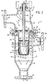
- Figure 2 is a cross section view of the direct contact steam injection heater of the present invention
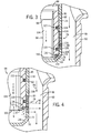
- Figure 3 is a magnified view taken along line 3-3 showing the interaction between the discharge region of the steam diffuser and the regulating member;
- Figure 4 is a view similar to Figure 3 showing the movement of the regulating member from the closed position to a partially open position;
- Figure 6 is a magnified view showing the impingement of a steam jet relative to the diameter of the diffusion hole.
- Figure 7 is a schematic illustration showing the preferred ratio between the diameter of the steam diffusion holes and the distance to the heater body sidewall.
- FIG. 1 generally shows a direct contact steam injection heater 10 constructed in accordance with the present invention.
- the injection heater 10 has a heater body 12 that includes a steam inlet 14, a liquid inlet 16 and a heated liquid product discharge outlet 18. Steam flows into the steam inlet 14 from a supply pipe 20.
- a liquid or slurry product to be heated enters the heater body 12 through an inlet pipe 22 that is coupled to the liquid inlet 16.
- a flow of steam is injected into the liquid flow such that the liquid flow is heated prior to exiting the heater body 12 at the heated liquid outlet 18.
- the steam injection heater 10 includes an actuator 24 that controls the amount of steam injected into the liquid flow in the manner to be described in greater detail below.
- the steam housing 26 includes an attachment flange 36 that is positioned in contact with a similar attachment flange 38 formed as part of the liquid housing 40.
- a series of connectors 42 are used to securely attach the steam housing 26 to the liquid housing 40 to define the heater body 12.
- the liquid housing 40 includes the liquid inlet 16, which is surrounded by flange 44 that facilitates attachment of the liquid inlet 16 to the supply pipe.
- the flow of liquid as represented by arrow 46, is directed into a combining region 48 generally defined by the open interior of the liquid housing 40.
- the combining region 48 is generally an open interior of the heater body 12 that is positioned below the liquid inlet 16.
- the combining region 48 is defined by the generally cylindrical outer wall 50 and has an internal diameter defined by the inner wall surface 52.
- the flow of liquid passes through the combining region 48 and reaches the inwardly sloping lower wall 54 that directs the flow of fluid toward the heater liquid outlet 18.
- the liquid outlet 18 is surrounded and defined by an attachment flange 56 used to attach the heater body 12 to a discharge pipe (not shown).
- a steam diffuser 58 is mounted across the upper opening 60 of the liquid housing 40 in axial alignment with the lower opening 32 of the steam housing 26.
- the steam diffuser 58 includes an outer wall 62 extending from an upper attachment flange 64.
- the attachment flange 64 includes a plurality of connectors 66 to secure the steam diffuser 58 to an attachment surface 68 extending around the upper opening 60.
- the outer wall 62 of the steam diffuser 58 is generally cylindrical and defines an open interior 70.
- the open interior 70 extends from an open upper end 72 to an end wall 74.
- the end wall 74 is joined to the side wall 62 by an angular, annular sealing surface 76.
- the steam diffuser 58 includes a discharge region 78 formed in the outer wall 62 slightly above the end wall 74.
- the discharge region 78 includes a plurality of steam diffusion holes 80 that each extend through the outer wall 62 to provide a flow passageway between the open interior 70 of the steam diffuser 58 and the combining region 48 such that steam can flow into the combining region 48 through the steam diffusion holes 80, as illustrated by arrows 82 in Figure 4.
- the steam diffusion holes 80 are equally distributed around the entire outer circumference of the generally cylindrical steam diffuser 58 such that steam can flow from within the steam diffuser into the flow of liquid around the entire outer circumference of the steam diffuser.
- the size and number of the steam diffusion holes 80 is a matter of design choice depending on the size of the heater; however, a diameter of about 1/16th of an inch is preferred in most applications. Such a diameter is sufficiently small to facilitate the creation of relatively small radial jets of steam through the diffuser outer wall 62, yet it is not so small as to create other problems such as scaling due to liquid characteristics.
- the steam diffuser 58 be made of stainless steel and that the outer wall 62 have a thickness sufficient to drive away premature deterioration as steam passes through the steam diffusion holes 80 over an extended period of time.
- the plurality of steam diffusion holes 80 are arranged at least in part longitudinally along the outer wall 62. As will be described below, the amount of steam supplied by the steam diffuser 58 into the liquid flowing through the combining region 48 can be modulated by moving a regulating member 84 to expose an increasing number of steam diffusion holes 80.
- steam injection heater 10 includes a regulating member 84 removably positioned within the open interior 70 of the steam diffuser 58.
- the regulating member 84 is movable along the longitudinal axis of the steam diffuser 58 to selectively control the amount of steam flow through the steam diffusion holes 80 in the discharge region 78.
- the regulating member 84 is coupled to a actuation stem 86 by a retaining pin 88.
- the actuation stem 86 passes through a top opening 90 formed in the steam housing 26 and is coupled to the actuator 24 shown in Figure 1.
- Packing material 92 surrounds the stem 86 and is held in place by a packing nut 94.
- the packing material 92 in combination with the packing nut 94 provide a seal around the actuator stem 86.
- the regulating member 84 is a piston defined by a cylindrical outer wall 96.
- the cylindrical outer wall 96 defines an open top end 98 and an open bottom end 100.
- the outer wall 96 defines a pair of spaced yokes 102 that each receive an end of the retaining pin 88.
- the flow of steam entering the steam diffuser 58 is allowed to flow into the regulating member 84 through the open top end 98, through the open interior 104 and out of the open bottom end 100.
- the seating member 112 When the regulating member 84 is in its completely closed seating position as shown in Figure 3, the seating member 112 creates a fluid tight end seal that prevents the steam within the open interior 104 from passing between the outer surface 108 of the regulating member 84 and the inner surface 118 of the outer wall 62. Thus, when the regulating member 84 is in its completely closed position, the seating member 112 prevents the flow of steam from reaching the steam diffusion holes 80 in the discharge region 78. As can be understood in Figure 4, the sloped contact surface 114 of the seating member 112 is recessed radially inward from the outer surface 108 and thus does not contact the steam diffusion holes 80, which significantly reduces the wear to the seating member 112.
- the first sealing member 120 When the regulating member 84 is in its completely closed, seated position, the first sealing member 120 is positioned below the discharge region 78 while the second sealing member 122 is positioned above the discharge region 78. Thus, the entire discharge region 78 is contained between the first sealing member 120 and the second sealing member 122. As described previously, when the regulating member 84 is in its completely closed, seated position, the seating member 112 prevents the flow of steam to the discharge region 78. When the regulating member 84 is fully seated, the first sealing member 120 and the second sealing member 122 provide a controlling seal to prevent the liquid flowing within the combining region 48 from entering into the steam diffuser past the discharge region 78.
- the seating member 112 is moved away from the sealing wall 76 such that steam is initially allowed to flow between the outer surface 108 of the regulating member 84 and the inner surface 118 of the outer wall 62.
- the first sealing member 120 functions as a controlling seal that allows controlled leakage of steam past the sealing member 120. Since the sealing member 120 is continuously moved along the series of steam diffusion holes 80 within the discharge region 78, the first sealing member 120 cannot be counted on to provide a liquid tight seal. Thus, the first sealing member 120 functions as a controlling member to allow a controlled leakage of steam to the discharge region 78.
- the first sealing member 120 exposes an increasing number of the steam diffusion holes 80.
- the first sealing member 120 is positioned above the discharge region 78 to expose all of the steam diffusion holes 80 contained within the discharge region 78, thereby allowing the maximum amount of steam to reach the combining region 48.
- Each of the steam diffusion holes 80 creates a steam jet 130 that enters into the flow of liquid 46 to heat the liquid.
- the first sealing member 120 allows a controlled flow of steam once the seating member 112 breaks contact with the sealing wall 76.
- the first sealing member 120 prevents excessive leakage past the seal.
- the controlled leakage of steam past the first sealing member 120 is important such that the amount of steam exiting the steam diffuser can closely track the position of the regulating member in order to offer adequate steam control. If the amount of steam leakage past the first sealing member 120 is excessive, too much steam will flow out of the discharge region 78 and it may be impossible to control the temperature of the discharged liquid at the lower end of the regulating member travel.
- the steam diffusion hole 132 has an increased diameter as compared to the steam diffusion hole 134.
- the differences in the diameter between the two steam diffusion holes 132 and 134 results in the first steam jet 136 having a greater size and volume as compared to the second steam jet 138.
- the first steam jet 136 contacts the outer wall 50 of the heater body, while the second steam jet 138 dissipates prior to contacting the outer wall 50.
- the steam velocity has been found to be highest when the pressure in the mixing or combining region 48 is less than the critical pressure of the incoming steam. This pressure is generally 57.5% of the absolute steam pressure.
- the steam velocity exiting in each of the jets 136,138 is essentially sonic and about 1,450 ft/sec. At discharge pressures higher than the critical pressure for the steam, the steam jet velocity is less and the jet length is shorter. The high velocity of steam is critical to the condensation effect but also can create a problem if the steam jet is not allowed to dissipate completely.
- the heater needs to be designed so that the steam jet is mostly condensed before the steam jet reaches the outer wall 50.
- the steam jet behavior is predictable through a known medium, such as water.
- the variables that can be altered are the diameter D of the steam diffusion holes and the distance L from the exit point of the steam to the opposing outer wall 50, as best shown in Figure 7.
- the optimal distance L from the steam diffusion holes 80 to the opposing outer wall 50 is at least eleven times the diameter D of the steam diffusion holes. If the distance L is less than eleven times the diameter D, a significant portion of the steam jet will impinge on the opposing wall 50 and the steam momentum will be lost. When this occurs, the steam forms overly large bubbles in the liquid being heated. These bubbles will cause noise and vibration when they eventually collapse and condense in the liquid.
- the steam diffusion holes have a diameter of approximately 1/16 th of an inch and the distance L to the wall 50 is at least 11/16 th of an inch.
- different hole diameters D and distances L could be utilized while operating within the scope of the present invention, as long as the distance L is at least eleven time the diffusion holes diameter D.
Landscapes
- Chemical & Material Sciences (AREA)
- Chemical Kinetics & Catalysis (AREA)
- Engineering & Computer Science (AREA)
- Mechanical Engineering (AREA)
- General Engineering & Computer Science (AREA)
- Jet Pumps And Other Pumps (AREA)
- Devices For Medical Bathing And Washing (AREA)
- Air Humidification (AREA)
- Turbine Rotor Nozzle Sealing (AREA)
Applications Claiming Priority (1)
| Application Number | Priority Date | Filing Date | Title |
|---|---|---|---|
| US11/051,769 US7152851B2 (en) | 2005-02-04 | 2005-02-04 | Steam injection heater with dual-sealing assembly |
Publications (3)
| Publication Number | Publication Date |
|---|---|
| EP1688691A2 true EP1688691A2 (de) | 2006-08-09 |
| EP1688691A3 EP1688691A3 (de) | 2007-12-19 |
| EP1688691B1 EP1688691B1 (de) | 2010-03-24 |
Family
ID=36284036
Family Applications (1)
| Application Number | Title | Priority Date | Filing Date |
|---|---|---|---|
| EP06250561A Expired - Lifetime EP1688691B1 (de) | 2005-02-04 | 2006-02-02 | Dampfeinspritzheizgerät mit doppelter Dichtungsanordnung |
Country Status (4)
| Country | Link |
|---|---|
| US (1) | US7152851B2 (de) |
| EP (1) | EP1688691B1 (de) |
| AT (1) | ATE462112T1 (de) |
| DE (1) | DE602006013058D1 (de) |
Cited By (5)
| Publication number | Priority date | Publication date | Assignee | Title |
|---|---|---|---|---|
| WO2010003090A1 (en) * | 2008-07-03 | 2010-01-07 | Hydro-Thermal Corportion | Steam injection heater with stationary end seal assembly |
| CN103889564A (zh) * | 2011-10-11 | 2014-06-25 | 流量控制有限责任公司 | 用于饮料应用的内嵌式按需可调节的碳酸饱和室 |
| EP2703070A3 (de) * | 2012-08-31 | 2015-02-11 | Krones AG | Misch-Regelventil und Verfahren |
| EP2916937A4 (de) * | 2012-11-06 | 2016-07-13 | Artec Holding As | Vorrichtung zum mischen von flüssiggas in einer flüssigkeit |
| CN106345361A (zh) * | 2016-11-07 | 2017-01-25 | 中国核动力研究设计院 | 一种用于高温高压条件下过热工质的高效混合器 |
Families Citing this family (18)
| Publication number | Priority date | Publication date | Assignee | Title |
|---|---|---|---|---|
| CA2898486C (en) * | 2010-05-20 | 2018-04-24 | William Matthew Martin | Method and device for in-line injection of flocculent agent into a fluid flow of mature fine tailings |
| CA2729457C (en) | 2011-01-27 | 2013-08-06 | Fort Hills Energy L.P. | Process for integration of paraffinic froth treatment hub and a bitumen ore mining and extraction facility |
| CA2906715C (en) | 2011-02-25 | 2016-07-26 | Fort Hills Energy L.P. | Process for treating high paraffin diluted bitumen |
| CA2733342C (en) | 2011-03-01 | 2016-08-02 | Fort Hills Energy L.P. | Process and unit for solvent recovery from solvent diluted tailings derived from bitumen froth treatment |
| CA2733862C (en) | 2011-03-04 | 2014-07-22 | Fort Hills Energy L.P. | Process and system for solvent addition to bitumen froth |
| CA2735311C (en) | 2011-03-22 | 2013-09-24 | Fort Hills Energy L.P. | Process for direct steam injection heating of oil sands bitumen froth |
| CA2815785C (en) | 2011-04-15 | 2014-10-21 | Fort Hills Energy L.P. | Heat recovery for bitumen froth treatment plant integration with temperature circulation loop circuits |
| CA2848254C (en) | 2011-04-28 | 2020-08-25 | Fort Hills Energy L.P. | Recovery of solvent from diluted tailings by feeding a desegregated flow to nozzles |
| CA2857700C (en) | 2011-05-04 | 2015-07-07 | Fort Hills Energy L.P. | Process for enhanced turndown in a bitumen froth treatment operation |
| CA2740935C (en) | 2011-05-18 | 2013-12-31 | Fort Hills Energy L.P. | Enhanced temperature control of bitumen froth treatment process |
| US8939382B1 (en) | 2011-07-13 | 2015-01-27 | Sioux Corporation | Steam-heated fluid pressure washer system |
| US9377243B2 (en) * | 2012-04-16 | 2016-06-28 | Prosonix Llc | High pressure steam injection heater assembly |
| US9207017B2 (en) * | 2012-04-23 | 2015-12-08 | Hydro-Thermal Corporation | Fluid diffusing nozzle design |
| AU2015303871B2 (en) | 2014-08-19 | 2018-11-29 | Archer Daniels Midland Company | Catalyst and process for producing 2,5-furandicarboxylic acid from hydromethylfurfural in water |
| CA3016784C (en) | 2018-09-07 | 2020-12-15 | Fort Hills Energy L.P. | Direct steam injection (dsi) heating and use in bitumen froth treatment operations |
| TWI685377B (zh) * | 2019-02-21 | 2020-02-21 | 亞泰半導體設備股份有限公司 | 高配比混料裝置與使用其的製劑生產系統 |
| US10674751B1 (en) * | 2019-02-21 | 2020-06-09 | Empirical Innovations, Inc. | Heating medium injectors and injection methods for heating foodstuffs |
| US12510242B2 (en) | 2020-10-08 | 2025-12-30 | Prosonix, Llc | Multimode direct injection heater assembly |
Citations (4)
| Publication number | Priority date | Publication date | Assignee | Title |
|---|---|---|---|---|
| US5622655A (en) | 1995-04-10 | 1997-04-22 | Hydro-Thermal Corporation | Sanitary direct contact steam injection heater and method |
| US5842497A (en) | 1996-05-20 | 1998-12-01 | Hydro-Thermal Corporation | Adjustable shear direct contact steam injection heater |
| US6082712A (en) | 1998-07-09 | 2000-07-04 | Hydro-Thermal Corporation | Direct contact steam injection heater |
| US6361025B1 (en) | 2000-04-11 | 2002-03-26 | Hydro-Thermal Corporation | Steam injection heater with transverse mounted mach diffuser |
Family Cites Families (8)
| Publication number | Priority date | Publication date | Assignee | Title |
|---|---|---|---|---|
| US2913232A (en) * | 1956-08-29 | 1959-11-17 | Cottrell Res Inc | Gas treating device |
| US3984504A (en) * | 1975-02-24 | 1976-10-05 | Pick Heaters, Inc. | Method and apparatus for preventing water hammer in high pressure steam injection water heaters |
| US4473512A (en) * | 1982-09-17 | 1984-09-25 | Pick Heaters, Inc. | Sanitary steam injection heater |
| US4732712A (en) * | 1987-05-28 | 1988-03-22 | Leslie Controls, Inc. | Steam injection water heater |
| CH685366A5 (fr) * | 1992-12-09 | 1995-06-30 | Nestle Sa | Dispositif de traitement d'un produit fluide par injection de vapeur. |
| US6186481B1 (en) * | 1999-04-27 | 2001-02-13 | Therm-Omega-Tech, Inc. | Quiet steam-water mixer |
| SE517823C2 (sv) * | 2000-11-29 | 2002-07-16 | Tetra Laval Holdings & Finance | Reglerbar ånginjektor |
| US7025338B2 (en) * | 2003-03-28 | 2006-04-11 | Hydro-Thermal Corporation | Seal and pressure relief for steam injection heater |
-
2005
- 2005-02-04 US US11/051,769 patent/US7152851B2/en not_active Expired - Lifetime
-
2006
- 2006-02-02 DE DE602006013058T patent/DE602006013058D1/de not_active Expired - Lifetime
- 2006-02-02 AT AT06250561T patent/ATE462112T1/de not_active IP Right Cessation
- 2006-02-02 EP EP06250561A patent/EP1688691B1/de not_active Expired - Lifetime
Patent Citations (4)
| Publication number | Priority date | Publication date | Assignee | Title |
|---|---|---|---|---|
| US5622655A (en) | 1995-04-10 | 1997-04-22 | Hydro-Thermal Corporation | Sanitary direct contact steam injection heater and method |
| US5842497A (en) | 1996-05-20 | 1998-12-01 | Hydro-Thermal Corporation | Adjustable shear direct contact steam injection heater |
| US6082712A (en) | 1998-07-09 | 2000-07-04 | Hydro-Thermal Corporation | Direct contact steam injection heater |
| US6361025B1 (en) | 2000-04-11 | 2002-03-26 | Hydro-Thermal Corporation | Steam injection heater with transverse mounted mach diffuser |
Cited By (10)
| Publication number | Priority date | Publication date | Assignee | Title |
|---|---|---|---|---|
| WO2010003090A1 (en) * | 2008-07-03 | 2010-01-07 | Hydro-Thermal Corportion | Steam injection heater with stationary end seal assembly |
| US8246015B2 (en) | 2008-07-03 | 2012-08-21 | Hydro-Thermal Corporation | Steam injection heater with stationary end seal assembly |
| CN103889564A (zh) * | 2011-10-11 | 2014-06-25 | 流量控制有限责任公司 | 用于饮料应用的内嵌式按需可调节的碳酸饱和室 |
| EP2766108A4 (de) * | 2011-10-11 | 2015-03-18 | Flow Control LLC | Einstellbare inline-karbonisierungskammer auf anfrage für getränkeanwendungen |
| US9033315B2 (en) | 2011-10-11 | 2015-05-19 | Flow Control Llc. | Adjustable in-line on demand carbonation chamber for beverage applications |
| CN103889564B (zh) * | 2011-10-11 | 2016-04-06 | 流量控制有限责任公司 | 用于饮料应用的内嵌式按需可调节的碳酸饱和室 |
| EP2703070A3 (de) * | 2012-08-31 | 2015-02-11 | Krones AG | Misch-Regelventil und Verfahren |
| EP2916937A4 (de) * | 2012-11-06 | 2016-07-13 | Artec Holding As | Vorrichtung zum mischen von flüssiggas in einer flüssigkeit |
| CN106345361A (zh) * | 2016-11-07 | 2017-01-25 | 中国核动力研究设计院 | 一种用于高温高压条件下过热工质的高效混合器 |
| CN106345361B (zh) * | 2016-11-07 | 2019-01-22 | 中国核动力研究设计院 | 一种用于高温高压条件下过热工质的高效混合器 |
Also Published As
| Publication number | Publication date |
|---|---|
| US7152851B2 (en) | 2006-12-26 |
| US20060175721A1 (en) | 2006-08-10 |
| EP1688691A3 (de) | 2007-12-19 |
| EP1688691B1 (de) | 2010-03-24 |
| DE602006013058D1 (de) | 2010-05-06 |
| ATE462112T1 (de) | 2010-04-15 |
Similar Documents
| Publication | Publication Date | Title |
|---|---|---|
| EP1688691B1 (de) | Dampfeinspritzheizgerät mit doppelter Dichtungsanordnung | |
| US8246015B2 (en) | Steam injection heater with stationary end seal assembly | |
| US8568017B2 (en) | Radial flow steam injection heater | |
| US6082712A (en) | Direct contact steam injection heater | |
| HUT63240A (en) | Conditioning valve | |
| EP0631803B1 (de) | Kombinierte Haupt- und Nebenstromvorrichtung zur Behandlung einer fluiden Substanz durch Filtration und/oder Zusatz einer oder mehrerer Chemikalie(n) | |
| EP0489018B1 (de) | Druckerniedrigung und konditionierungsventil | |
| ES2255709T3 (es) | Modulo de cavidad reducida con asiento intercambiable. | |
| US6361025B1 (en) | Steam injection heater with transverse mounted mach diffuser | |
| US8167278B2 (en) | Angled diffuser and steam injection heater assembly | |
| WO2002086361A1 (en) | Pivot actuated sleeve valve | |
| KR20100080403A (ko) | 동심 통로를 통과하는 유동 제어에 관한 방법, 장치 및/또는 시스템 | |
| AU2005255173A1 (en) | Thermostatic cartridge for the regulation of hot and cold fluids to be mixed, and mixer tap comprising one such cartridge | |
| CN110360329B (zh) | 供与流体阀一起使用的净化装置 | |
| EP2657634B1 (de) | Gestaltung einer Diffusordüse für Fluide | |
| CN102792005A (zh) | 燃料压力调节器的不平衡入口燃料管 | |
| US4597529A (en) | Self-regulating spray methods and apparatus | |
| MX2012014033A (es) | Un aparato de anillo de asiento de atemperador. | |
| FI102313B (fi) | Palloventtiili, jossa on epäkeskeinen läpimenokanava | |
| US20180020868A1 (en) | Device for continuous heating of fluids | |
| US788764A (en) | Hydrocarbon-burner. | |
| US12510242B2 (en) | Multimode direct injection heater assembly | |
| RU2121097C1 (ru) | Клапан для регулирования расхода горячего газа | |
| US7201181B1 (en) | Mixing valve | |
| RU96109546A (ru) | Пневматическая форсунка |
Legal Events
| Date | Code | Title | Description |
|---|---|---|---|
| PUAI | Public reference made under article 153(3) epc to a published international application that has entered the european phase |
Free format text: ORIGINAL CODE: 0009012 |
|
| AK | Designated contracting states |
Kind code of ref document: A2 Designated state(s): AT BE BG CH CY CZ DE DK EE ES FI FR GB GR HU IE IS IT LI LT LU LV MC NL PL PT RO SE SI SK TR |
|
| AX | Request for extension of the european patent |
Extension state: AL BA HR MK YU |
|
| PUAL | Search report despatched |
Free format text: ORIGINAL CODE: 0009013 |
|
| AK | Designated contracting states |
Kind code of ref document: A3 Designated state(s): AT BE BG CH CY CZ DE DK EE ES FI FR GB GR HU IE IS IT LI LT LU LV MC NL PL PT RO SE SI SK TR |
|
| AX | Request for extension of the european patent |
Extension state: AL BA HR MK YU |
|
| 17P | Request for examination filed |
Effective date: 20080605 |
|
| AKX | Designation fees paid |
Designated state(s): AT BE BG CH CY CZ DE DK EE ES FI FR GB GR HU IE IS IT LI LT LU LV MC NL PL PT RO SE SI SK TR |
|
| GRAP | Despatch of communication of intention to grant a patent |
Free format text: ORIGINAL CODE: EPIDOSNIGR1 |
|
| GRAS | Grant fee paid |
Free format text: ORIGINAL CODE: EPIDOSNIGR3 |
|
| GRAA | (expected) grant |
Free format text: ORIGINAL CODE: 0009210 |
|
| AK | Designated contracting states |
Kind code of ref document: B1 Designated state(s): AT BE BG CH CY CZ DE DK EE ES FI FR GB GR HU IE IS IT LI LT LU LV MC NL PL PT RO SE SI SK TR |
|
| REG | Reference to a national code |
Ref country code: GB Ref legal event code: FG4D |
|
| REG | Reference to a national code |
Ref country code: CH Ref legal event code: EP |
|
| REG | Reference to a national code |
Ref country code: IE Ref legal event code: FG4D |
|
| REF | Corresponds to: |
Ref document number: 602006013058 Country of ref document: DE Date of ref document: 20100506 Kind code of ref document: P |
|
| REG | Reference to a national code |
Ref country code: NL Ref legal event code: T3 |
|
| PG25 | Lapsed in a contracting state [announced via postgrant information from national office to epo] |
Ref country code: LT Free format text: LAPSE BECAUSE OF FAILURE TO SUBMIT A TRANSLATION OF THE DESCRIPTION OR TO PAY THE FEE WITHIN THE PRESCRIBED TIME-LIMIT Effective date: 20100324 |
|
| LTIE | Lt: invalidation of european patent or patent extension |
Effective date: 20100324 |
|
| PG25 | Lapsed in a contracting state [announced via postgrant information from national office to epo] |
Ref country code: SI Free format text: LAPSE BECAUSE OF FAILURE TO SUBMIT A TRANSLATION OF THE DESCRIPTION OR TO PAY THE FEE WITHIN THE PRESCRIBED TIME-LIMIT Effective date: 20100324 Ref country code: PL Free format text: LAPSE BECAUSE OF FAILURE TO SUBMIT A TRANSLATION OF THE DESCRIPTION OR TO PAY THE FEE WITHIN THE PRESCRIBED TIME-LIMIT Effective date: 20100324 Ref country code: AT Free format text: LAPSE BECAUSE OF FAILURE TO SUBMIT A TRANSLATION OF THE DESCRIPTION OR TO PAY THE FEE WITHIN THE PRESCRIBED TIME-LIMIT Effective date: 20100324 Ref country code: FI Free format text: LAPSE BECAUSE OF FAILURE TO SUBMIT A TRANSLATION OF THE DESCRIPTION OR TO PAY THE FEE WITHIN THE PRESCRIBED TIME-LIMIT Effective date: 20100324 Ref country code: LV Free format text: LAPSE BECAUSE OF FAILURE TO SUBMIT A TRANSLATION OF THE DESCRIPTION OR TO PAY THE FEE WITHIN THE PRESCRIBED TIME-LIMIT Effective date: 20100324 |
|
| PG25 | Lapsed in a contracting state [announced via postgrant information from national office to epo] |
Ref country code: SE Free format text: LAPSE BECAUSE OF FAILURE TO SUBMIT A TRANSLATION OF THE DESCRIPTION OR TO PAY THE FEE WITHIN THE PRESCRIBED TIME-LIMIT Effective date: 20100324 Ref country code: RO Free format text: LAPSE BECAUSE OF FAILURE TO SUBMIT A TRANSLATION OF THE DESCRIPTION OR TO PAY THE FEE WITHIN THE PRESCRIBED TIME-LIMIT Effective date: 20100324 Ref country code: BE Free format text: LAPSE BECAUSE OF FAILURE TO SUBMIT A TRANSLATION OF THE DESCRIPTION OR TO PAY THE FEE WITHIN THE PRESCRIBED TIME-LIMIT Effective date: 20100324 Ref country code: EE Free format text: LAPSE BECAUSE OF FAILURE TO SUBMIT A TRANSLATION OF THE DESCRIPTION OR TO PAY THE FEE WITHIN THE PRESCRIBED TIME-LIMIT Effective date: 20100324 Ref country code: GR Free format text: LAPSE BECAUSE OF FAILURE TO SUBMIT A TRANSLATION OF THE DESCRIPTION OR TO PAY THE FEE WITHIN THE PRESCRIBED TIME-LIMIT Effective date: 20100625 Ref country code: ES Free format text: LAPSE BECAUSE OF FAILURE TO SUBMIT A TRANSLATION OF THE DESCRIPTION OR TO PAY THE FEE WITHIN THE PRESCRIBED TIME-LIMIT Effective date: 20100705 |
|
| PG25 | Lapsed in a contracting state [announced via postgrant information from national office to epo] |
Ref country code: BG Free format text: LAPSE BECAUSE OF FAILURE TO SUBMIT A TRANSLATION OF THE DESCRIPTION OR TO PAY THE FEE WITHIN THE PRESCRIBED TIME-LIMIT Effective date: 20100624 Ref country code: SK Free format text: LAPSE BECAUSE OF FAILURE TO SUBMIT A TRANSLATION OF THE DESCRIPTION OR TO PAY THE FEE WITHIN THE PRESCRIBED TIME-LIMIT Effective date: 20100324 Ref country code: IS Free format text: LAPSE BECAUSE OF FAILURE TO SUBMIT A TRANSLATION OF THE DESCRIPTION OR TO PAY THE FEE WITHIN THE PRESCRIBED TIME-LIMIT Effective date: 20100724 Ref country code: CZ Free format text: LAPSE BECAUSE OF FAILURE TO SUBMIT A TRANSLATION OF THE DESCRIPTION OR TO PAY THE FEE WITHIN THE PRESCRIBED TIME-LIMIT Effective date: 20100324 |
|
| PLBE | No opposition filed within time limit |
Free format text: ORIGINAL CODE: 0009261 |
|
| STAA | Information on the status of an ep patent application or granted ep patent |
Free format text: STATUS: NO OPPOSITION FILED WITHIN TIME LIMIT |
|
| PG25 | Lapsed in a contracting state [announced via postgrant information from national office to epo] |
Ref country code: DK Free format text: LAPSE BECAUSE OF FAILURE TO SUBMIT A TRANSLATION OF THE DESCRIPTION OR TO PAY THE FEE WITHIN THE PRESCRIBED TIME-LIMIT Effective date: 20100324 Ref country code: PT Free format text: LAPSE BECAUSE OF FAILURE TO SUBMIT A TRANSLATION OF THE DESCRIPTION OR TO PAY THE FEE WITHIN THE PRESCRIBED TIME-LIMIT Effective date: 20100726 |
|
| 26N | No opposition filed |
Effective date: 20101228 |
|
| PG25 | Lapsed in a contracting state [announced via postgrant information from national office to epo] |
Ref country code: IT Free format text: LAPSE BECAUSE OF FAILURE TO SUBMIT A TRANSLATION OF THE DESCRIPTION OR TO PAY THE FEE WITHIN THE PRESCRIBED TIME-LIMIT Effective date: 20100324 |
|
| PG25 | Lapsed in a contracting state [announced via postgrant information from national office to epo] |
Ref country code: MC Free format text: LAPSE BECAUSE OF NON-PAYMENT OF DUE FEES Effective date: 20110228 |
|
| REG | Reference to a national code |
Ref country code: CH Ref legal event code: PL |
|
| PG25 | Lapsed in a contracting state [announced via postgrant information from national office to epo] |
Ref country code: LI Free format text: LAPSE BECAUSE OF NON-PAYMENT OF DUE FEES Effective date: 20110228 Ref country code: CH Free format text: LAPSE BECAUSE OF NON-PAYMENT OF DUE FEES Effective date: 20110228 |
|
| REG | Reference to a national code |
Ref country code: IE Ref legal event code: MM4A |
|
| PG25 | Lapsed in a contracting state [announced via postgrant information from national office to epo] |
Ref country code: IE Free format text: LAPSE BECAUSE OF NON-PAYMENT OF DUE FEES Effective date: 20110202 |
|
| PG25 | Lapsed in a contracting state [announced via postgrant information from national office to epo] |
Ref country code: CY Free format text: LAPSE BECAUSE OF FAILURE TO SUBMIT A TRANSLATION OF THE DESCRIPTION OR TO PAY THE FEE WITHIN THE PRESCRIBED TIME-LIMIT Effective date: 20100324 Ref country code: LU Free format text: LAPSE BECAUSE OF NON-PAYMENT OF DUE FEES Effective date: 20110202 |
|
| PG25 | Lapsed in a contracting state [announced via postgrant information from national office to epo] |
Ref country code: TR Free format text: LAPSE BECAUSE OF FAILURE TO SUBMIT A TRANSLATION OF THE DESCRIPTION OR TO PAY THE FEE WITHIN THE PRESCRIBED TIME-LIMIT Effective date: 20100324 |
|
| PG25 | Lapsed in a contracting state [announced via postgrant information from national office to epo] |
Ref country code: HU Free format text: LAPSE BECAUSE OF FAILURE TO SUBMIT A TRANSLATION OF THE DESCRIPTION OR TO PAY THE FEE WITHIN THE PRESCRIBED TIME-LIMIT Effective date: 20100324 |
|
| PGFP | Annual fee paid to national office [announced via postgrant information from national office to epo] |
Ref country code: NL Payment date: 20140311 Year of fee payment: 9 |
|
| REG | Reference to a national code |
Ref country code: NL Ref legal event code: V1 Effective date: 20150901 |
|
| PG25 | Lapsed in a contracting state [announced via postgrant information from national office to epo] |
Ref country code: NL Free format text: LAPSE BECAUSE OF NON-PAYMENT OF DUE FEES Effective date: 20150901 |
|
| REG | Reference to a national code |
Ref country code: FR Ref legal event code: PLFP Year of fee payment: 11 |
|
| REG | Reference to a national code |
Ref country code: FR Ref legal event code: PLFP Year of fee payment: 12 |
|
| PGFP | Annual fee paid to national office [announced via postgrant information from national office to epo] |
Ref country code: DE Payment date: 20170228 Year of fee payment: 12 |
|
| REG | Reference to a national code |
Ref country code: FR Ref legal event code: PLFP Year of fee payment: 13 |
|
| PGFP | Annual fee paid to national office [announced via postgrant information from national office to epo] |
Ref country code: GB Payment date: 20180328 Year of fee payment: 13 |
|
| PGFP | Annual fee paid to national office [announced via postgrant information from national office to epo] |
Ref country code: FR Payment date: 20180320 Year of fee payment: 13 |
|
| REG | Reference to a national code |
Ref country code: DE Ref legal event code: R119 Ref document number: 602006013058 Country of ref document: DE |
|
| PG25 | Lapsed in a contracting state [announced via postgrant information from national office to epo] |
Ref country code: DE Free format text: LAPSE BECAUSE OF NON-PAYMENT OF DUE FEES Effective date: 20180901 |
|
| GBPC | Gb: european patent ceased through non-payment of renewal fee |
Effective date: 20190202 |
|
| PG25 | Lapsed in a contracting state [announced via postgrant information from national office to epo] |
Ref country code: GB Free format text: LAPSE BECAUSE OF NON-PAYMENT OF DUE FEES Effective date: 20190202 |
|
| PG25 | Lapsed in a contracting state [announced via postgrant information from national office to epo] |
Ref country code: FR Free format text: LAPSE BECAUSE OF NON-PAYMENT OF DUE FEES Effective date: 20190228 |