EP1689063A1 - Systeme d'alimentation electrique - Google Patents
Systeme d'alimentation electrique Download PDFInfo
- Publication number
- EP1689063A1 EP1689063A1 EP04772113A EP04772113A EP1689063A1 EP 1689063 A1 EP1689063 A1 EP 1689063A1 EP 04772113 A EP04772113 A EP 04772113A EP 04772113 A EP04772113 A EP 04772113A EP 1689063 A1 EP1689063 A1 EP 1689063A1
- Authority
- EP
- European Patent Office
- Prior art keywords
- lithium ion
- power supply
- ion battery
- charging
- charging current
- Prior art date
- Legal status (The legal status is an assumption and is not a legal conclusion. Google has not performed a legal analysis and makes no representation as to the accuracy of the status listed.)
- Withdrawn
Links
Images




Classifications
-
- H—ELECTRICITY
- H02—GENERATION; CONVERSION OR DISTRIBUTION OF ELECTRIC POWER
- H02J—ELECTRIC POWER NETWORKS; CIRCUIT ARRANGEMENTS OR SYSTEMS FOR SUPPLYING OR DISTRIBUTING ELECTRIC POWER; SYSTEMS FOR STORING ELECTRIC ENERGY
- H02J7/00—Circuit arrangements for charging or discharging batteries or for supplying loads from batteries
- H02J7/02—Circuit arrangements for charging or discharging batteries or for supplying loads from batteries for charging batteries from AC mains by converters
- H02J7/04—Regulation of charging current or voltage
-
- H—ELECTRICITY
- H02—GENERATION; CONVERSION OR DISTRIBUTION OF ELECTRIC POWER
- H02J—ELECTRIC POWER NETWORKS; CIRCUIT ARRANGEMENTS OR SYSTEMS FOR SUPPLYING OR DISTRIBUTING ELECTRIC POWER; SYSTEMS FOR STORING ELECTRIC ENERGY
- H02J9/00—Circuit arrangements for emergency or stand-by power supply, e.g. for emergency lighting
- H02J9/04—Circuit arrangements for emergency or stand-by power supply, e.g. for emergency lighting in which the distribution system is disconnected from the normal source and connected to a standby source
- H02J9/06—Circuit arrangements for emergency or stand-by power supply, e.g. for emergency lighting in which the distribution system is disconnected from the normal source and connected to a standby source with automatic change-over, e.g. UPS systems
- H02J9/061—Circuit arrangements for emergency or stand-by power supply, e.g. for emergency lighting in which the distribution system is disconnected from the normal source and connected to a standby source with automatic change-over, e.g. UPS systems for DC powered loads
-
- H—ELECTRICITY
- H02—GENERATION; CONVERSION OR DISTRIBUTION OF ELECTRIC POWER
- H02J—ELECTRIC POWER NETWORKS; CIRCUIT ARRANGEMENTS OR SYSTEMS FOR SUPPLYING OR DISTRIBUTING ELECTRIC POWER; SYSTEMS FOR STORING ELECTRIC ENERGY
- H02J7/00—Circuit arrangements for charging or discharging batteries or for supplying loads from batteries
- H02J7/34—Parallel operation in networks using both storage and other DC sources, e.g. providing buffering
-
- H—ELECTRICITY
- H02—GENERATION; CONVERSION OR DISTRIBUTION OF ELECTRIC POWER
- H02J—ELECTRIC POWER NETWORKS; CIRCUIT ARRANGEMENTS OR SYSTEMS FOR SUPPLYING OR DISTRIBUTING ELECTRIC POWER; SYSTEMS FOR STORING ELECTRIC ENERGY
- H02J7/00—Circuit arrangements for charging or discharging batteries or for supplying loads from batteries
- H02J7/60—Circuit arrangements for charging or discharging batteries or for supplying loads from batteries including safety or protection arrangements
- H02J7/61—Circuit arrangements for charging or discharging batteries or for supplying loads from batteries including safety or protection arrangements against overcharge
-
- H—ELECTRICITY
- H02—GENERATION; CONVERSION OR DISTRIBUTION OF ELECTRIC POWER
- H02J—ELECTRIC POWER NETWORKS; CIRCUIT ARRANGEMENTS OR SYSTEMS FOR SUPPLYING OR DISTRIBUTING ELECTRIC POWER; SYSTEMS FOR STORING ELECTRIC ENERGY
- H02J7/00—Circuit arrangements for charging or discharging batteries or for supplying loads from batteries
- H02J7/90—Regulation of charging or discharging current or voltage
- H02J7/96—Regulation of charging or discharging current or voltage in response to battery voltage
-
- H—ELECTRICITY
- H02—GENERATION; CONVERSION OR DISTRIBUTION OF ELECTRIC POWER
- H02J—ELECTRIC POWER NETWORKS; CIRCUIT ARRANGEMENTS OR SYSTEMS FOR SUPPLYING OR DISTRIBUTING ELECTRIC POWER; SYSTEMS FOR STORING ELECTRIC ENERGY
- H02J7/00—Circuit arrangements for charging or discharging batteries or for supplying loads from batteries
- H02J7/60—Circuit arrangements for charging or discharging batteries or for supplying loads from batteries including safety or protection arrangements
- H02J7/62—Circuit arrangements for charging or discharging batteries or for supplying loads from batteries including safety or protection arrangements against overcurrent
-
- H—ELECTRICITY
- H02—GENERATION; CONVERSION OR DISTRIBUTION OF ELECTRIC POWER
- H02J—ELECTRIC POWER NETWORKS; CIRCUIT ARRANGEMENTS OR SYSTEMS FOR SUPPLYING OR DISTRIBUTING ELECTRIC POWER; SYSTEMS FOR STORING ELECTRIC ENERGY
- H02J7/00—Circuit arrangements for charging or discharging batteries or for supplying loads from batteries
- H02J7/60—Circuit arrangements for charging or discharging batteries or for supplying loads from batteries including safety or protection arrangements
- H02J7/63—Circuit arrangements for charging or discharging batteries or for supplying loads from batteries including safety or protection arrangements against overdischarge
Definitions
- the present invention relates to a power supply system having a constitution in which a lithium ion battery for backup is connected in parallel to a DC power supply apparatus and a load device.
- a valve-regulated lead-acid battery is mainly used for backup in a power supply system that supplies electrical power to a load device such as a communication device.
- Valve-regulated lead-acid batteries have come to be widely used in communication devices because of their low cost and the benefits they bring in terms of system configuration. Such benefits include performing maintenance charging required for capacity preservation and recovery charging after a power outage by maintaining a constant voltage.
- Valve-regulated lead-acid batteries have conventionally been employed in order to meet such demands.
- valve-regulated lead-acid batteries there have been limits to downsizing due to restrictions imposed on the current value during high-current discharge. This has as a result led to restrictions on downsizing the power supply system as well.
- a lithium ion battery provides the aforementioned characteristics and has the characteristic of being suited to constant-voltage charging in the manner of a valve-regulated lead-acid battery. Therefore, use of a lithium ion battery can realize a power supply system that allows downsizing and enlargement of capacity.
- the battery is connected to a charging device during charging and when fully charged is disconnected from the charging device or has its connection switched to a load device to supply power thereto (refer, for example, to Japanese Unexamined Patent Application No. H04-331425).
- the present invention has as its object to provide a power supply system that can protect a battery from overcharging or prevent a drop in capacity of a lithium ion battery and realizes a constant connection to eliminate the need for connection switching or disconnecting of the lithium ion battery. It is another object of the present invention to provide a power supply system that prevents variations in the cell voltage of each lithium ion battery during charging.
- the present invention provides a power supply system comprising: a DC power supply apparatus; a load device; a lithium ion battery for backup that is connected in parallel with said DC power supply apparatus and said load device; a charging path; a charging current limiting circuit that is connected in series with said lithium ion battery and supplies a charging current of an arbitrary value independent of load fluctuations in the charging path of the lithium ion battery; a switch that disconnects said lithium ion battery from said DC power supply apparatus or said load device, or connects said lithium ion battery to said DC power supply apparatus or said load device; and a control circuit that monitors the voltage value of said charging path, sets a reference voltage setting used for setting the charging current of an arbitrary value in said charging current limiting circuit, and controls said switch when said voltage of said charging path exceeds a specified voltage value during charging.
- the power supply system performs disconnection from said DC power supply apparatus or said load device or performs connection to said DC power supply apparatus or said load device.
- a plurality of said lithium ion batteries are connected in series, and said power supply system is further provided with a voltage regulation circuit that is connected in parallel with each lithium ion battery of said plurality of series-connected lithium ion batteries, detects a full-charge voltage in each of the lithium ion batteries and bypasses the charging current.
- the present invention provides a power supply system comprising: a DC power supply apparatus; a load device; a plurality of series-connected lithium ion batteries that are connected in parallel with said DC power supply apparatus and said load device; a charging current limiting circuit that is connected in series with said plurality of lithium ion batteries and supplies a charging current of an arbitrary value independent of load fluctuations in the charging path of said plurality of lithium ion batteries; a switch that disconnects said plurality of lithium ion batteries from said DC power supply apparatus or said load device, or connects said plurality of lithium ion batteries to said DC power supply apparatus or said load device; a voltage regulation circuit that is connected in parallel with each lithium ion battery of said plurality of series-connected lithium ion batteries, detects a full-charge voltage in each lithium ion battery and bypasses said charging current; and a control circuit that monitors the voltage value and current value of said charging path, sets a reference voltage used for setting a charging current of an arbitrary value in
- the charging current limiting circuit that is connected in series with said lithium ion battery supplies a charging current of an arbitrary value independent of load fluctuations in the charging path of the lithium ion battery.
- the present invention makes possible constant connection between a DC power supply apparatus or load device and a lithium ion battery, without switching or disconnecting the DC power supply apparatus or load device and a lithium ion battery themselves, by connecting or disconnecting the lithium ion battery to/from said DC power supply apparatus or said load device with a switch.
- the present invention can limit the charging current for the lithium ion battery to an arbitrary current value, and perform recovery charging with an optimal charging current that is suited to the capacity of the installed lithium ion battery.
- the present invention detects a full-charge voltage in each of the lithium ion batteries for bypassing said charging current, adjusts variations among the charge voltages for the lithium ion batteries during charging, can avoid overcharging and can avoid drops in capacity due to overcharging.
- the lithium ion batteries are always connected to the DC power supply apparatus or said load device, but the voltage regulation circuit operates to adjust the charge voltages of all the lithium ion batteries to a uniform charge voltage when variations occur among the charge voltages of the lithium ion batteries due to a change in the impedances within the lithium ion batteries when the lithium ion batteries are fully charged.
- FIG. 1 is a block diagram showing one embodiment of the power supply system of the present invention.
- the power supply system of the present invention is constituted of a lithium ion battery 1 for backup that is connected in parallel with a DC power supply apparatus 2 and a load device 3, and furthermore a charging current limiting circuit 4, a voltage regulation circuit 5, a switch 6, and a control circuit 7.
- the DC power supply apparatus 2 is provided in a plurality.
- the charging current limiting circuit 4 is connected in series with the lithium ion battery 1, limiting the charging current in the charging path of the lithium ion battery 1 so as to charge the lithium ion battery 1 with a constant current independent of load fluctuations.
- the switch 6 disconnects the lithium ion battery 1 from the DC power supply apparatus 2 or the load device 3, or else connects the lithium ion battery 1 to the DC power supply apparatus 2 or the load device 3.
- the voltage regulation circuit 5 is connected in parallel with each lithium ion battery of a plurality of the lithium ion batteries 1 connected in series, and has a function of detecting a full-charge voltage in each of the lithium ion batteries and bypassing the charging current around the lithium ion battery.
- the control circuit 7 is constituted of a microcomputer, and has a function of monitoring the voltage value and current value of the charging path by means of a current measurement portion 8 and a voltage measurement portion 9, setting a reference voltage used for setting an arbitrary charging current value in the charging current limiting circuit 4 and a full-charge reference voltage in the voltage regulation circuit 5, and switching the switch 6 when the voltage of a charging path exceeds a specified voltage value during charging.
- the switch 6, which is used to protect the lithium ion battery 1 from overcharging and over-discharging, is connected in series with the charging/discharging path of the lithium ion battery 1.
- the switch 6 is mainly used for circuit disconnection to protect the lithium ion battery 1, whereby the switch 6 becomes "open” when the cell voltage rises to a voltage that is the rated voltage of the battery.
- the switch 6 can be used for protecting the lithium ion battery 1 from over-discharging, whereby when the voltage of an arbitrary lithium ion battery 1 falls to a specified value during discharging, the switch 6 becomes "open” to protect the lithium ion battery 1.
- the return of the switch 6 is performed manually in the case of overcharging, and automatically in the case of over-discharging.
- the DC power supply apparatus 2 may be constituted with one unit, however, a redundant constitution is adopted here as a system for a communication device.
- the reference voltage value of the voltage regulation circuit 5 and the limiting current value of the charging current limiting circuit 4 are set by the control circuit 7 that is constituted by a microcomputer.
- the control circuit 7 has a function to measure the voltage and current at any location in the power supply system.
- the current measurement portion 8 detects the current using a shunt resistor or the like, with the current measurement portion 8 being monitored by the control circuit 7.
- control circuit 7 monitors the voltage of each cell.
- the control circuit 7 detects when the cell voltage has exceeded the safe operating range of the lithium ion battery 1 during charging and opens the switch 6 disposed in the charging/discharging path of the lithium ion battery 1. Thereby, it is possible to ensure the safety of the lithium ion battery 1.
- the aforementioned constitution can switch the connection of the lithium ion battery 1 from the DC power supply apparatus 2 and the load device 3 or allow constant connection without performing disconnection. In addition, it can restrict the charging current of the lithium ion battery 1 to an arbitrarily determined current value, and perform recovery charging with an optimal charging current that is suited to the capacity of the installed lithium ion battery 1.
- the lithium ion batteries 1 are always connected to the DC power supply apparatus 2 and the load apparatus 3, when the lithium ion batteries 1 are fully charged, variations among the charge voltages of the lithium ion batteries 1 occur due to changes in the internal impedances of the lithium ion batteries 1.
- the operation of the voltage regulation circuits 5 can adjust the charge voltages of all the lithium ion batteries 1 to a uniform charge voltage.
- FIG 4 is a graph showing the power supply state of the power supply system during charging.
- the DC power supply apparatus 2 supplies electric power to the load device 3 while charging the lithium ion battery 1.
- the charging current to the lithium ion battery 1 will fluctuate.
- the charging current limiting circuit 4 is connected to the charging path of the lithium ion battery 1 and set to an arbitrary charging current value. Thereby, even when the power supply state of the load device 3 fluctuates, the lithium ion battery 1 can be charged with a constant charging current value.
- FIG. 5 is a graph showing the power supply state during charging of a power supply system that has a charging current limiting circuit.
- the charging current value of the charging current limiting circuit 4 can be arbitrarily set by the state or capacity of the lithium ion battery 1. High-current discharge is possible during discharging of the lithium ion battery 1, with discharge by a current that is 5 to 6 times the normal capacity also possible (in the case of a battery rating of 50Ah, this works out to 250A to 300A). However, during charging, a current value of one to one-tenth of the normal capacity is the maximum allowed value (in the case of a battery rating of 50Ah, this is 5A to 50A). The charging current value of the charging current limiting circuit 4 is thus set based on the capacity of the lithium ion battery 1.
- FIG. 2 shows one embodiment of the charging current limiting circuit 4 shown in FIG. 1.
- the charging current limiting circuit 4 is constituted of an error amplifier A 41; an error amplifier B 42 which has as inputs the output of the error amplifier A 41 and the reference voltage for setting the arbitrary charging current; a charging current control element 43 such as a transistor or the like; and a charging current detecting element 44 such as, for example, a resistor or the like.
- the charging current is detected by the charging current detecting element 44, and that value is amplified to a specified value by the error amplifier A 41.
- the amplified value is then input to the error amplifier B 42 so as to be the reference of the current value set arbitrarily. Then by controlling the charging current control element 43 with that output, it becomes a constant current value.
- the charging current control element 43 no longer limits the current. Also, the current that is required for the load device 3 is discharged from the lithium ion battery 1 during discharge, but at that time the charging current limiting circuit 4 does not restrict the discharge current. During discharge, for example, a diode or the like that bypasses the charging current limiting circuit 4 shown in FIG. 2 may be connected.
- FIG. 6 shows the current-voltage state of the lithium ion battery 1 during charging and when fully charged.
- this graph shows the case of using two (A and B) lithium ion batteries 1.
- FIG 3 shows one embodiment of the voltage regulation circuit.
- the voltage regulation circuit 5 is constituted by an error amplifier C 51 and a charging current bypass circuit 52 in which a bypass current control element 521 and a bypass current limiting element 522 are connected in series.
- the voltage regulation circuit 5 connected in parallel with each lithium ion battery 1 (A and B) detects the charge voltage.
- the charging current of the lithium ion battery A that is fully charged is bypassed around the lithium ion battery A by the charging current bypass circuit 52 in the voltage regulation circuit 5, thereby averting overcharging.
- the charging current bypass circuit 52 is constituted by the bypass current limiting element 522, such as a resistor or the like, that determines the maximum value of the bypassed current, and the bypass current control element 521, such as a transistor, that controls the current value of the bypassed current.
- the bypass current control element 521 such as a transistor, that controls the current value of the bypassed current.
- the transistor acts as a variable resistor.
- the value of the bypassed current can be continuously varied.
- the charging current becomes a minute current when the lithium ion battery 1 approaches a fully charged state
- continuously operating the bypass current control element 521 means being able to bypass even this minute current.
- the amount of the bypassed current is controlled by the voltage regulation circuit 5. That is, by inputting the full-charge reference voltage and the detected value of the charge voltage in each lithium ion battery 1 into the error amplifier C 51, the bypass current control element 521 of the charging current bypass circuit 52 is controlled. Thus, only the required amount of the charging current is continuously bypassed by the charging current bypass circuit 52 so that the voltage of each lithium ion battery 1 does not exceed the full-charge voltage.
- the charging current set in the charging current limiting circuit 4 continues to flow until all the lithium ion batteries reach full charge.
- the voltage regulation circuit 5 operates to bypass the charging current by means of the charging current bypass circuit 52 until all the lithium ion batteries 1 become fully charged.
- the lithium ion batteries 1 are connected to the DC power supply apparatus 2 and the load device 3. Therefore, although there is no charging or discharging of the lithium ion batteries 1 in this state, by being connected to the DC power supply apparatus 2 their full-charge state is maintained. Since the voltage regulation circuit 5 is also connected without being separated from the lithium ion batteries 1, all the lithium ion batteries 1 are maintained by a uniform charge voltage.
- the charge voltage may become non-uniform. In this case as well, the charge voltages are kept uniform by the operation of the voltage regulation circuit 5.
- the internal impedance of the lithium ion battery A becomes higher due to fluctuation while the lithium ion battery A is in a full-charge state, leading to a rise in the charge voltage.
- the voltage regulation circuit 5 which takes the full-charge voltage as a reference, works to operate the charging current bypass circuit 52, with the increased portion of the charge voltage discharging by the bypassed current. Therefore, the lithium ion battery A whose charge voltage attempts to rise is held at the full-charge voltage.
- the charge voltages across the individual lithium ion batteries 1 can therefore maintain a uniform state. Since the lithium ion batteries 1 are always receiving a uniform charge voltage, even when supplying power to the load device 3, the performance of the lithium ion batteries 1 can be utilized to the maximum extent.
- FIG. 7 shows the embodiment of the charging current limiting circuit 4.
- a resistor R100 is used for the charging current detecting element 44, and an FET Q100 is used for the charging current control element 43.
- a plurality of the FETs Q100 are used in parallel connection in accordance with the loss. Also, during discharge the FET Q100 forms a discharge path by being turned completely ON, or the FET Q100 forms a discharging path by being turned OFF and using the parasitic diode D100 of the FET Q100.
- the charging current detected by the resistor R100 is input to the differential amplifier constituted by resistors R1 to R4 and the error amplifier A 41, where it is amplified to a value determined in advance.
- the output thereof is then input to the inverted input terminal of the error amplifier B 42 through a resistor R7.
- the reference voltage that sets the charging current is divided by the resistors R5 and R6 from the control circuit 7 and input to the non-inverted input of the error amplifier B 42.
- Resistors R8 and R9 and a condenser C1 are connected to the error amplifier B 42 for the purpose of stabilizing the control of the charging current.
- the output of the error amplifier B 42 is input to the base of the transistor Q1 via a resistor R10.
- the transistor Q1 provides a signal to the gate of the charging current control element Q100 to control the charging current by the FET Q100.
- a resistor R12 and a condenser C2 are connected between the gate and the source of the FET Q100 for the purpose of stable operation of the FET Q100.
- a diode D1 is a diode for input protection of the error amplifier B 42.
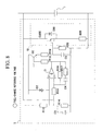
- FIG. 8 shows the embodiment of the voltage regulation circuit 5.
- a resistor R200 is used for the bypass current limiting element 522
- an FET Q200 is used for the bypass current control element 521.
- the voltage of the lithium ion battery 1 is detected and input to the inverted input of the error amplifier C 51 via a resistor R15, and the reference voltage from the control circuit 7 is input to the non-inverted input terminal of the error amplifier C 51 via resistors R13 and R14 and a condenser C3.
- the error amplifier C 51 outputs an output signal so that the two inputs become the same value.
- the output signal is input to the base of a transistor Q2 via a resistor R18.
- the transistor Q2 provides a signal to the gate of the bypass current control element Q200 via a resistor R19 to control the bypassed current, performing control so that the voltage of the lithium ion battery becomes the same as the reference voltage.
- resistors R16 and R17 and a condenser C4 are connected to the error amplifier C 51 to stabilize the control.
- a diode D2 is used for input protection of the error amplifier C 51.
- a resistor R20 and a condenser C5 connect between the gate and the source of the FET Q200 for stable operation of the FET Q200.
- FIG. 9 shows such a constitution.
- an AC adaptor 90 receives the feed of a commercial 100V power supply from outside and converts it to 16.4V DC via an AC/DC converter.
- a DC/DC converter 102 then produces a voltage (5V to 15V) suitable for the load device 103 such as the CPU inside a personal computer 100, and supplies it to the load device 103.
- a charging device 92 is provided in the AC adaptor 90, instead of a PC body 100, to avoid increasing the weight of the PC body 100.
- a lithium ion battery 101 in the PC body 100 here consists of four cylindrical lithium ion batteries 101 such as size AA batteries (4.1V ⁇ 4) connected in series, which receive charging from the charging device 92 and supply electrical power to the load device 103.
- the aforementioned voltage regulation circuit (not shown) is connected to each of the lithium ion batteries 101 in parallel. Therefore, even if the lithium ion batteries 101 undergo repeated charging, no overcharging occurs, thereby preventing a reduction in capacity of the lithium ion batteries 101. As a result, a reduction in the running time of the personal computer due to continuous use can be avoided.
- the charging current limiting circuit 4 connected in series with the lithium ion battery 1 (101) supplies a charging current of an arbitrary value to the charging path of the lithium ion batteries so that they are charged by a constant current independent of load fluctuations. Also, by disconnecting the lithium ion batteries 1 from the DC power supply apparatus 2 or the load device 3 by using the switch 6, or connecting the lithium ion batteries 1 to the DC power supply apparatus 2 or the load device 3, the connection of the DC power supply apparatus 2 and the load device 3 with the lithium ion batteries 1 (101) can be always performed. Moreover, the charging current of the lithium ion batteries 1 (101) can be restricted to an arbitrary current, and recovery charging can be performed with an optimal charging current that is suited to the capacity of the lithium ion batteries 1 (101).
- the voltage regulation circuit 5 is connected in parallel with each lithium ion battery 1 of the plurality of lithium ion batteries 1 (101) connected in series. Thereby, variations in the charge voltages of each lithium ion battery 1 in the lithium ion battery 1 during charging can be adjusted to avoid overcharging by detecting the full-charge voltage of each lithium ion battery 1 and bypassing the charging current. Furthermore, the lithium ion batteries 1 (101) are always connected to the DC power supply apparatus 2 and the load device 3, however, during full charge of the lithium ion battery 1 (101), variations among the charge voltages of the lithium ion batteries 1 (101) may occur due to changes in the internal impedances of the lithium ion battery 1 (101). In this case, the operation of the voltage regulation circuit 5 can adjust the charge voltages of all the lithium ion batteries 1 (101) to a uniform charge voltage.
Landscapes
- Engineering & Computer Science (AREA)
- Power Engineering (AREA)
- Business, Economics & Management (AREA)
- Emergency Management (AREA)
- Charge And Discharge Circuits For Batteries Or The Like (AREA)
- Secondary Cells (AREA)
- Stand-By Power Supply Arrangements (AREA)
Applications Claiming Priority (2)
| Application Number | Priority Date | Filing Date | Title |
|---|---|---|---|
| JP2003397489A JP2005160251A (ja) | 2003-11-27 | 2003-11-27 | 電力供給システム |
| PCT/JP2004/012152 WO2005053132A1 (fr) | 2003-11-27 | 2004-08-18 | Systeme d'alimentation electrique |
Publications (1)
| Publication Number | Publication Date |
|---|---|
| EP1689063A1 true EP1689063A1 (fr) | 2006-08-09 |
Family
ID=34631539
Family Applications (1)
| Application Number | Title | Priority Date | Filing Date |
|---|---|---|---|
| EP04772113A Withdrawn EP1689063A1 (fr) | 2003-11-27 | 2004-08-18 | Systeme d'alimentation electrique |
Country Status (6)
| Country | Link |
|---|---|
| US (1) | US20070103118A1 (fr) |
| EP (1) | EP1689063A1 (fr) |
| JP (2) | JP2005160251A (fr) |
| KR (1) | KR100825512B1 (fr) |
| CN (1) | CN100433498C (fr) |
| WO (1) | WO2005053132A1 (fr) |
Cited By (2)
| Publication number | Priority date | Publication date | Assignee | Title |
|---|---|---|---|---|
| WO2009151388A3 (fr) * | 2008-06-10 | 2011-04-07 | Telefonaktiebolaget L M Ericsson (Publ) | Procédé et agencement dans un système de puissance |
| EP2690747A3 (fr) * | 2012-07-24 | 2014-12-03 | Lite-On Technology Corporation | Système de commande, système d'alimentation électrique et procédé pour empêcher une charge flottante d'une batterie |
Families Citing this family (23)
| Publication number | Priority date | Publication date | Assignee | Title |
|---|---|---|---|---|
| US20060119320A1 (en) * | 2004-12-03 | 2006-06-08 | Linear Technology Corporation | Current control circuitry and methodology for controlling current from current source |
| US7733061B2 (en) * | 2004-12-29 | 2010-06-08 | Linear Technology Corporation | Current control circuitry and methodology for controlling current from current constrained source |
| US20070235783A9 (en) * | 2005-07-19 | 2007-10-11 | Micron Technology, Inc. | Semiconductor constructions, memory arrays, electronic systems, and methods of forming semiconductor constructions |
| US7710079B2 (en) * | 2005-07-19 | 2010-05-04 | Linear Technology Corporation | Power manager and power managing method for battery-powered application |
| US7772672B2 (en) | 2005-09-01 | 2010-08-10 | Micron Technology, Inc. | Semiconductor constructions |
| US7799694B2 (en) | 2006-04-11 | 2010-09-21 | Micron Technology, Inc. | Methods of forming semiconductor constructions |
| KR100855984B1 (ko) * | 2007-02-27 | 2008-09-02 | 삼성전자주식회사 | 향상된 셋업 전압 특성을 갖는 기준전압 발생기 및 이를제어하는 방법 |
| FR2926934B1 (fr) * | 2008-01-29 | 2010-09-17 | Saft Groupe Sa | Systeme electronique pour batterie |
| JP4766095B2 (ja) * | 2008-10-09 | 2011-09-07 | ソニー株式会社 | 充電装置 |
| CN101621214B (zh) * | 2009-07-28 | 2012-09-19 | 成都市华为赛门铁克科技有限公司 | 电池备份模块、电池备份模块的供电方法及存储系统 |
| JP5432761B2 (ja) * | 2010-02-12 | 2014-03-05 | 株式会社マキタ | 複数のバッテリパックを電源とする電動工具 |
| JP5461221B2 (ja) | 2010-02-12 | 2014-04-02 | 株式会社マキタ | 複数のバッテリパックを電源とする電動工具 |
| DE102010003703A1 (de) | 2010-04-08 | 2011-11-17 | Robert Bosch Gmbh | Verfahren und Vorrichtung zum Aufladen einer Batterie |
| JP5794982B2 (ja) * | 2010-05-11 | 2015-10-14 | 大西 徳生 | 電源装置及び充電回路 |
| JP6030066B2 (ja) * | 2011-10-27 | 2016-11-24 | 三洋電機株式会社 | 電池ユニット、電動車両、移動体、電源装置及び電池制御装置 |
| US20170250551A1 (en) * | 2014-09-22 | 2017-08-31 | Polyvalor, Limited Partnership | Energy storage device and modular circuit |
| JP6261522B2 (ja) * | 2015-01-05 | 2018-01-17 | 東芝三菱電機産業システム株式会社 | 二次電池充電システム |
| RU2625456C1 (ru) * | 2016-03-15 | 2017-07-14 | Алексей Николаевич Ворошилов | Система эксплуатации литий-ионной аккумуляторной батареи в режиме поддерживающего заряда |
| US10992144B2 (en) * | 2017-05-17 | 2021-04-27 | Galley Power LLC | Battery balancing and current control with bypass circuit for load switch |
| MY198913A (en) | 2018-11-15 | 2023-10-02 | Toshiba Kk | Charging/discharging control device and dc power supply system |
| CN112993422A (zh) * | 2019-12-18 | 2021-06-18 | 致茂电子(苏州)有限公司 | 储能单元充电方法 |
| JP7481147B2 (ja) * | 2020-03-31 | 2024-05-10 | Fdk株式会社 | 電池電圧均等化装置 |
| DE102022100612A1 (de) * | 2022-01-12 | 2023-07-13 | Miele & Cie. Kg | Akkumulator mit Batteriemanagementsystem |
Family Cites Families (13)
| Publication number | Priority date | Publication date | Assignee | Title |
|---|---|---|---|---|
| JPS5579636A (en) * | 1978-12-12 | 1980-06-16 | Yuasa Battery Co Ltd | Dc power supply |
| US5402055A (en) * | 1992-09-30 | 1995-03-28 | Compaq Computer Corporation | AC adapter including differential comparator for tracking battery voltage during trickle charge |
| JP3428015B2 (ja) * | 1992-10-23 | 2003-07-22 | ソニー株式会社 | バッテリーパック |
| JP3229696B2 (ja) * | 1993-02-25 | 2001-11-19 | 三洋電機株式会社 | 電池の充電方法 |
| JPH08265987A (ja) * | 1995-03-20 | 1996-10-11 | Integuran Kk | 直列電池の充電電圧分配装置 |
| JPH1066276A (ja) * | 1996-08-21 | 1998-03-06 | Japan Tobacco Inc | 充電保護装置および充電装置 |
| US5952815A (en) * | 1997-07-25 | 1999-09-14 | Minnesota Mining & Manufacturing Co. | Equalizer system and method for series connected energy storing devices |
| JP3347300B2 (ja) * | 1999-06-10 | 2002-11-20 | エヌイーシートーキン栃木株式会社 | シリーズ接続電池用保護回路及び該保護回路を備えた電池パック並びにバックアップ電源装置 |
| US6501249B1 (en) * | 1999-10-13 | 2002-12-31 | Xicor, Inc. | Battery management system |
| JP2002010505A (ja) * | 2000-06-16 | 2002-01-11 | Fuji Electric Co Ltd | 充電制御装置 |
| WO2002061917A1 (fr) * | 2001-02-01 | 2002-08-08 | Hitachi Maxell, Ltd. | Source d'energie |
| JP3665574B2 (ja) * | 2001-02-09 | 2005-06-29 | セイコーインスツル株式会社 | 充放電制御回路と充電式電源装置 |
| US6583603B1 (en) * | 2002-02-08 | 2003-06-24 | Peco Ii, Inc. | Back-up battery management apparatus and method for charging and testing battery cells in a string of battery cells |
-
2003
- 2003-11-27 JP JP2003397489A patent/JP2005160251A/ja active Pending
-
2004
- 2004-08-18 KR KR1020067009533A patent/KR100825512B1/ko not_active Expired - Fee Related
- 2004-08-18 CN CNB2004800345497A patent/CN100433498C/zh not_active Expired - Fee Related
- 2004-08-18 US US10/580,630 patent/US20070103118A1/en not_active Abandoned
- 2004-08-18 WO PCT/JP2004/012152 patent/WO2005053132A1/fr not_active Ceased
- 2004-08-18 EP EP04772113A patent/EP1689063A1/fr not_active Withdrawn
-
2007
- 2007-01-15 JP JP2007006383A patent/JP2007129898A/ja active Pending
Non-Patent Citations (1)
| Title |
|---|
| See references of WO2005053132A1 * |
Cited By (2)
| Publication number | Priority date | Publication date | Assignee | Title |
|---|---|---|---|---|
| WO2009151388A3 (fr) * | 2008-06-10 | 2011-04-07 | Telefonaktiebolaget L M Ericsson (Publ) | Procédé et agencement dans un système de puissance |
| EP2690747A3 (fr) * | 2012-07-24 | 2014-12-03 | Lite-On Technology Corporation | Système de commande, système d'alimentation électrique et procédé pour empêcher une charge flottante d'une batterie |
Also Published As
| Publication number | Publication date |
|---|---|
| JP2007129898A (ja) | 2007-05-24 |
| KR100825512B1 (ko) | 2008-04-25 |
| US20070103118A1 (en) | 2007-05-10 |
| JP2005160251A (ja) | 2005-06-16 |
| KR20060107532A (ko) | 2006-10-13 |
| CN1883098A (zh) | 2006-12-20 |
| WO2005053132A1 (fr) | 2005-06-09 |
| CN100433498C (zh) | 2008-11-12 |
Similar Documents
| Publication | Publication Date | Title |
|---|---|---|
| EP1689063A1 (fr) | Systeme d'alimentation electrique | |
| US7969119B2 (en) | Overvoltage protection | |
| KR101054584B1 (ko) | 충전 방법, 전지 팩 및 그 충전기 | |
| US6037750A (en) | Battery pack controller | |
| US6329796B1 (en) | Power management circuit for battery systems | |
| US5886503A (en) | Back-up battery management apparatus for charging and testing individual battery cells in a string of battery cells | |
| US8860372B2 (en) | Multiple cell battery charger configured with a parallel topology | |
| KR100297608B1 (ko) | 충전제어장치, 이를 구비한 충방전장치 및 전자기기 | |
| TWI751229B (zh) | 控制裝置、控制系統、蓄電裝置以及電腦可讀取媒體 | |
| US11146094B2 (en) | Electrical apparatus | |
| US10199844B2 (en) | Power-supplying device | |
| KR20140048737A (ko) | 배터리 팩 및 배터리 팩의 제어 방법 | |
| CN101799491A (zh) | 多节电池组保护电路 | |
| CN108011415B (zh) | 一种集成电池保护的电源管理单元芯片 | |
| US20060186857A1 (en) | Rechargeable battery with charge control | |
| KR20170060849A (ko) | 배터리 팩 및 이를 포함하는 전기 구동 차량 | |
| JP5489779B2 (ja) | リチウムイオン組電池の充電システムおよび充電方法 | |
| RU2408958C1 (ru) | Способ эксплуатации литий-ионной аккумуляторной батареи в автономной системе электропитания искусственного спутника земли | |
| KR19990037303A (ko) | 셀용 충전 전류 어댑터 회로 또는 배터리들 | |
| US5438252A (en) | Power supply control module for a battery control system of an appliance, and a battery equipped with such a module | |
| JP2006223050A (ja) | 電力供給システム | |
| KR101639885B1 (ko) | 정전압원 기능을 갖는 배터리 보조 장치 및 이를 포함하는 배터리 팩 | |
| US20040251877A1 (en) | Voltage adapter circuit for a lithium ion rechargeable battery | |
| KR100574037B1 (ko) | 개별 충전이 가능한 배터리 충전장치 | |
| EP1253696A1 (fr) | Methode de charge de batterie |
Legal Events
| Date | Code | Title | Description |
|---|---|---|---|
| PUAI | Public reference made under article 153(3) epc to a published international application that has entered the european phase |
Free format text: ORIGINAL CODE: 0009012 |
|
| 17P | Request for examination filed |
Effective date: 20060525 |
|
| AK | Designated contracting states |
Kind code of ref document: A1 Designated state(s): GB |
|
| DAX | Request for extension of the european patent (deleted) | ||
| RBV | Designated contracting states (corrected) |
Designated state(s): GB |
|
| STAA | Information on the status of an ep patent application or granted ep patent |
Free format text: STATUS: THE APPLICATION IS DEEMED TO BE WITHDRAWN |
|
| 18D | Application deemed to be withdrawn |
Effective date: 20130301 |