EP1689310B1 - Dentalhandstück mit einem körper aus einem stück und mit einem elektronischen und elastischen element zur verbindung zwischen den mechanischen übertragungselementen und dem kopf des instruments - Google Patents
Dentalhandstück mit einem körper aus einem stück und mit einem elektronischen und elastischen element zur verbindung zwischen den mechanischen übertragungselementen und dem kopf des instruments Download PDFInfo
- Publication number
- EP1689310B1 EP1689310B1 EP04787419.3A EP04787419A EP1689310B1 EP 1689310 B1 EP1689310 B1 EP 1689310B1 EP 04787419 A EP04787419 A EP 04787419A EP 1689310 B1 EP1689310 B1 EP 1689310B1
- Authority
- EP
- European Patent Office
- Prior art keywords
- head
- piece according
- instrument
- hand
- dental hand
- Prior art date
- Legal status (The legal status is an assumption and is not a legal conclusion. Google has not performed a legal analysis and makes no representation as to the accuracy of the status listed.)
- Expired - Lifetime
Links
Images

Classifications
-
- A—HUMAN NECESSITIES
- A61—MEDICAL OR VETERINARY SCIENCE; HYGIENE
- A61C—DENTISTRY; APPARATUS OR METHODS FOR ORAL OR DENTAL HYGIENE
- A61C1/00—Dental machines for boring or cutting ; General features of dental machines or apparatus, e.g. hand-piece design
- A61C1/08—Machine parts specially adapted for dentistry
- A61C1/14—Tool-holders, i.e. operating tool holders, e.g. burr holders
- A61C1/141—Tool-holders, i.e. operating tool holders, e.g. burr holders in an angled handpiece
-
- A—HUMAN NECESSITIES
- A61—MEDICAL OR VETERINARY SCIENCE; HYGIENE
- A61C—DENTISTRY; APPARATUS OR METHODS FOR ORAL OR DENTAL HYGIENE
- A61C1/00—Dental machines for boring or cutting ; General features of dental machines or apparatus, e.g. hand-piece design
- A61C1/08—Machine parts specially adapted for dentistry
-
- A—HUMAN NECESSITIES
- A61—MEDICAL OR VETERINARY SCIENCE; HYGIENE
- A61C—DENTISTRY; APPARATUS OR METHODS FOR ORAL OR DENTAL HYGIENE
- A61C1/00—Dental machines for boring or cutting ; General features of dental machines or apparatus, e.g. hand-piece design
- A61C1/08—Machine parts specially adapted for dentistry
- A61C1/10—Straight hand-pieces
-
- A—HUMAN NECESSITIES
- A61—MEDICAL OR VETERINARY SCIENCE; HYGIENE
- A61C—DENTISTRY; APPARATUS OR METHODS FOR ORAL OR DENTAL HYGIENE
- A61C1/00—Dental machines for boring or cutting ; General features of dental machines or apparatus, e.g. hand-piece design
- A61C1/08—Machine parts specially adapted for dentistry
- A61C1/12—Angle hand-pieces
-
- A—HUMAN NECESSITIES
- A61—MEDICAL OR VETERINARY SCIENCE; HYGIENE
- A61C—DENTISTRY; APPARATUS OR METHODS FOR ORAL OR DENTAL HYGIENE
- A61C1/00—Dental machines for boring or cutting ; General features of dental machines or apparatus, e.g. hand-piece design
- A61C1/08—Machine parts specially adapted for dentistry
- A61C1/14—Tool-holders, i.e. operating tool holders, e.g. burr holders
-
- A—HUMAN NECESSITIES
- A61—MEDICAL OR VETERINARY SCIENCE; HYGIENE
- A61C—DENTISTRY; APPARATUS OR METHODS FOR ORAL OR DENTAL HYGIENE
- A61C19/00—Dental auxiliary appliances
- A61C19/04—Measuring instruments specially adapted for dentistry
- A61C19/042—Measuring instruments specially adapted for dentistry for determining the position of a root apex
Definitions
- the invention relates to a new type of dental handpiece.
- the generally known dental handpieces are of two types straight handpieces and contra-angle handpieces.
- the body In the case of handpieces contra-angle the body consists of a handle having an elbow and a head.
- This structure leads to an embodiment that imposes at least two parts for the body and very often three to allow the assembly of the internal organs, and which also imposes several bearings, at least three.
- US5902105 is known a dental treatment apparatus having a function of measuring the length of the root canal of a tooth.
- the apparatus comprises a multi-part handpiece provided with a tool-holder assembly for attaching and rotating a dental instrument around a drive shaft and a chain of mechanical transmission members. rotational movement, said mechanical members also serving to conduction of the electric current.
- the document EP937440 discloses a dental handpiece whose handle and head body is formed of a single piece of polymer molded by pressure injection.
- a first object of the invention is to propose a new concept of handpiece structure that can replace the current concept of handpieces, and allowing the realization of the body in one piece whether for handpieces with mechanical drive or for air turbine driven handpieces.
- the head contains a turbine and the body of the handpiece comprises fluid channels necessary for operation.
- the inner housing of the head is adapted to receive a tool-holder assembly composed of mechanical transmission members of the head, and to receive a loosening clamping means of the tool or instrument, said housing opening on the head through an opening closable by a cap or hat, or by a push-button.
- the handpiece comprises a device for fixing a dental instrument to a tool-holder assembly for fixing and rotating a dental tool or instrument around a drive shaft, said assembly carrying tool being integrated in a head of a dental handpiece, and coupled to a motion transmission assembly, integrated into a handle of said handpiece, and composed mainly of a deformable and resiliently shaped clamping-loosening means belt, at least a portion of which has a section adapted to engage in an annular groove or groove which is provided in the upper part of the instrument and able to hold said instrument by clamping the instrument, said clamping means loosening also comprising means for exerting loosening forces from canceling the clamping forces to release the instrument.
- said fixing device is removable relative to the tool holder.
- the belt of elastic deformable material has a substantially parallelogram shape with a central zone designed to grip the head of the instrument at a groove.
- the deformable elastic belt has the form of a split ring or a split annular claw having an annular shoulder adapted to engage in an annular groove of the instrument and a conical portion to cooperate with a complementary part conical of a push button.
- the fixing device can comprise a push button, integral or not with the tool holder, and can be held for example by clipping into an opening of the head .
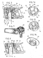
- a handpiece (1) consists of a body (2) in one piece comprising a portion serving as a handle (3) of rectilinear axis and a portion constituting a head (4), for fixing and driving an instrument (5) along a driving axis (6) which can be aligned with the axis of the handle (7) or can form a predetermined angle therebetween, between 90 and 180 ° and preferably between 100 ° and 130 °, as in the non-limiting example of the figures.
- the body is formed of an outer casing (8) or carcass, monobloc or not, which may be electrically insulating and may for example be made of a polymer material, thermoplastic or thermosetting, (preferably polyether-ether ketone abbreviated PEEK in the text) incorporating the mechanical components of the handle and the head as well as electrical connection means, ensuring the transmission of movement and electrical energy from a connection (9) provided at the end of the handle to cooperate with an external motor , not shown, to the instrument (5) fixed in the head (4).
- a connection 9 provided at the end of the handle to cooperate with an external motor , not shown, to the instrument (5) fixed in the head (4).
- the contra-angle (1) according to the invention represented on the Figures 1 to 3 has two axes (6) and (7) to limit the hazards of friction specific to each bearing and this, to ensure the most stable yield possible, which is why in this case, ball bearings are also integrated in the envelope (8).
- Such an arrangement of the contra-angle is particularly suitable for root canal treatment (endodontics) with apex locator.
- a handpiece according to the invention connected to and coupled to a motor can thus generate, for example, a rotation of an instrument (5) (channel instrument for example) and thereby convey a usable electric current for the detection of the apex.
- the electrical connection between motor and handpiece can be done by any means of connection for example between a coupling finger of the motor and a latching groove (10) of a sleeve (11) (or by telescopic pusher for example).
- the envelope (8), insulating, is maintained by the practitioner, and its head end (4) is environment the patient's mouth.
- the chain of mechanical and electrical transmission members is constituted as follows in the handle: the electric current passes from the bushing (11) to a fixed outer ring of a first bearing (12), and to a first spring (13), then to a fixed outer ring of a second bearing (14), then to a ring (15) stopped axially by a first shoulder in the envelope (8), then to a spring (16) stopped axially by a second shoulder of the envelope (8).
- the first and second bearings (12, 14) carry a transmission shaft along the longitudinal axis (7) of the handle, or first axis of the handpiece (1), and the springs (13 and 16) are springs with compression whose turns are arranged externally to the transmission shaft (7).
- the head (4) of the contra-angle supports two ball bearings (angular contact if possible) namely an upper bearing (17) whose outer ring cooperates with the second spring (16) of the handle and a lower bearing (18) whose axial play is caught by means of a spring washer (19).
- a pinion (20) mounted on the drive shaft (6) has teeth (21) meshing with the teeth (22) of an output gear (23) of the handle.
- the pinion (20) is conductive and integral with the inner rings of the bearings, it provides electrical driving to the instrument (5) and the mechanical drive thereof.
- the electric current conveyed to the end of the instrument will delimit the apex by a resistance variation effect, taking into account the external insulation of the envelope (8) and a pushbutton (55). ) provided on the head (4) and will be described later.
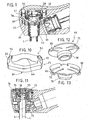
- the electrical connection between the second bearing (14) and the head (40) of the instrument is provided by an elastic connection member (88) and electrically conductive, the mechanical drive of the instrument being as previously provided by the sprocket (20).
- Said connecting member (88) is for example a lamella, or a rod of circular or rectangular section and comprises a first peripheral segment (89) engaged in a groove (90) formed in the ring (15) of the bearing (14) and a second peripheral segment (91), on the end opposite to the first segment, which bears on the head of the instrument (40), said connecting member being held perpendicular to the axis of the instrument when the push button is inactivated, thanks to the groove (90).
- This variant is particularly advantageous because on the one hand a pressing on the push button (55) tends to push the head of the instrument (40), and because on the other hand the contact of the connecting member on the head (40) is centered on the axis of the instrument through the spherical surface of said head, resulting in a friction speed close to zero.
- the housing (26) of the tool holder assembly (24) there is firstly a lower portion (29) cylindrical coaxial with the drive shaft (6) and whose diameter is adapted to receive the barrel (30) of the sprocket (20), and secondly a substantially cylindrical upper portion (31), also coaxial with the drive shaft (6), and of larger diameter and adapted to receive the toothing ( 21) of the pinion-fut with its engagement means of the instrument and the clamping-loosening device thereof described later.
- the opening (27) opening the upper portion of the housing (31) is closed by a plug or cap (28), preferably but not necessarily the same material as the casing (8).
- the upper part of the housing (31) also has a lateral opening (32) opening into an inner housing (33) of the handle (3) so as to allow meshing of the toothing of the pinion-fut (20) with the toothing the output gear (23) of the handle (3).
- the resulting axial freedom of said sprocket is a few hundredths of a millimeter.
- the clamping-loosening means is essentially composed of a belt (25) of deformable and elastic material having a substantially diamond-like shape with a central zone (39) designed to grip the head (40) of the instrument at the level of an annular locking groove (41) provided at the upper end of the instrument.
- the large diagonal diamond is provided so that its two ends project diametrically from the envelope of the head (4) by two projections (42) each placed in a notch (43) of the head, each notch (43) opening a part in the upper part (31) of the housing, on the other hand in the opening (27) receiving the cap.
- the blanks (44) of the notches provide locking in rotation of the belt, which is centered in the head by means of recesses (45) provided near the projections (42) and resting on the periphery (46) of the part upper housing (26).
- the axial holding of the belt is provided on the one hand by a shoulder (47) provided in the bottom (48) of an axial cavity (49) of the cap for receiving the head of the instrument (40) and of on the other hand by the bottom (50) of the notches.
- said belt cooperates with an upper shoulder (51) of the annular groove of the head of the instrument to make a first axial limitation of said instrument, the other axial limitation being provided by a flat part (52) of the sprocket cooperating with the end (53) transverse of the flat part of the instrument.
- Unlocking the instrument consists in exerting two diametrically opposed supports on the projections (42), directed towards the axis of rotation. These two forces cause an orthogonal component thus releasing the instrument. Pressing simultaneously and directly on the two ears of the belt (with your thumb and forefinger for example) ensures tightness in the mouth, compared to the push-button system, for example.
- the attachment of the instrument can be done without support on the two ears of the belt through the arrangement of a conical portion (64) formed in the underside of the central zone (39) in the belt, the axial displacement of the instrument translating a radial displacement of the belt, by elasticity, the belt returns to its shape to ensure the clamping function.
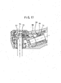
- the elastic belt (25) with a diamond shape and a central zone (39) for gripping the instrument differs from the previous one by its ears (54) forming projections perpendicular to the plane of the belt and located on the same side of it, and in that it is held axially and radially by the sprocket as shown in Figures 8 to 9 .
- the head differs from the previous one in that the plug is replaced by a push button (55) with metal insert for example (to facilitate manufacturing).
- the introduction of the instrument into the head can be done by pressing the push button, or without pressing the push button, in this case a conical arrangement (64) in the underside of the central zone (39) of the belt allows the introduction of the instrument.
- Miniaturization is a constant research in the field of medical equipment such as, for example, the heads of contra-angles in dentistry.
- New materials such as thermoplastic or thermosetting polymer materials meet this expectation.
- Known mechanisms can be reconsidered taking into account the mechanical, physical and chemical characteristics of these new materials by reducing the number of components, improving the quality, and lowering the cost of the whole; these plastic parts can be machined or injected.
- these plastic materials in addition to miniaturization, bring lightness, sliding ability, for dynamic equipment, good behavior for sterilization or disinfection, good elastic characteristics. This is why these plastic materials can be used in the realization of dental parts.
- the control of the tightening or loosening of the tool is usually done by a manual action on the push button of the head of the handpiece.
- this push button can be integral with the dynamic assembly (rotating, vibrating, etc.) for endodontics, for example, and with a fixed push button, independent of the dynamic assembly.
- a head body (4) monobloc or not with the handle (3), receives a rotating sprocket (20) rotated by an output gear (23) of the handle.
- the pinion-drum thus has a freedom in rotation and an axial connection ensured for example by ball bearings.
- the transmission of the milling rotation movement is ensured by the combination of the flat part (36) formed in the pinion-drum (4) and the flat part (37) of the tool.
- the axial holding of the tool is guaranteed in one direction by the shoulder of the flat part of the pinion-drum and by the shoulder of the flat part complementary to the tool.
- FIG 8 is an axial section of the figure 9 and which shows that the head has a cavity (83) provided around or adjacent the barrel-sprocket barrel for containing a solid fat which is released at each use in small amounts through an orifice (84) in the wall (85) of the barrel. separation between the cavity and the barrel to lubricate the barrel.
Landscapes
- Health & Medical Sciences (AREA)
- Oral & Maxillofacial Surgery (AREA)
- Dentistry (AREA)
- Epidemiology (AREA)
- Life Sciences & Earth Sciences (AREA)
- Animal Behavior & Ethology (AREA)
- General Health & Medical Sciences (AREA)
- Public Health (AREA)
- Veterinary Medicine (AREA)
- Dental Tools And Instruments Or Auxiliary Dental Instruments (AREA)
Claims (26)
- Dentalhandstück (1), umfassend mechanische Organe, die eine Werkzeughalteranordnung zur Befestigung und zum Drehantrieb eines zahnärztlichen Instruments um eine Antriebsachse (6) und eine Kette von Organen zur mechanischen Übertragung der Drehbewegung umfasst, wobei die mechanischen Organe innerhalb eines Körpers (2), der einen Kopf (4) und einen Griff (3) umfasst, montiert sind, wobeia) der Körper (2) aus einem elektrisch isolierenden Stück oder Umhüllung (8) gebildet ist, von dem ein Teil als Griff (3) dient und der andere Teil einen Kopf (4) bildet, wobei der Kopf eine erste Ausnehmung (26) umfasst, die mit mindestens einer Öffnung (27) ausmündet, die dimensioniert ist, um das Einführen der Organe des Kopfes und deren Montage im Inneren des letzteren zu ermöglichen, wobei der Griff eine zweite Ausnehmung (33) mit geradliniger Achse (7) umfasst, die einerseits am Ende des Griffs mit einer Öffnung (81) und andererseits in die erste Ausnehmung mit einer Seitenöffnung (32) ausmündet, wobei die Öffnung (81) dimensioniert ist, um das Einführen der inneren Organe des Griffs und deren Montage im Inneren des letzteren zu ermöglichen,b) in dem Griff läuft der elektrische Strom von einer Buchse (11) zur Verbindung mit einem Motor über die Kette von Organen zur mechanischen Übertragung der Drehbewegung, die wie folgt besteht:- in dem Griff läuft der elektrische Strom von einer Buchse (11) zu einem festen Aussenring eines ersten Lagers (12) und zu einer ersten Feder (13), anschließend zu einem festen Aussenring eines zweiten Lagers (14), danach zu einem Ring (15), der axial durch einen ersten Schulter in der Umhüllung (8) gestoppt wird, danach zu einer Feder (16), die axial durch einen zweiten Schulter der Umhüllung (8) gestoppt wird, wobei die ersten und zweiten Lager (12, 14) eine Antriebswelle entlang der Längsachse (7) des Griffs oder der ersten Achse des Handstücks (1) tragen und die Federn (13 und 16) Druckfedern sind, deren Windungen außerhalb der Antriebswelle (7) angeordnet sind,- in dem Kopf (4) des Winkelstücks, mit seiner zweiten Achse oder Antriebswelle (6), die zwei Kugellagern unterstützt, nämlich ein oberes Lager (17), dessen Aussenring mit der zweiten Feder (16) des Griffs zusammenwirkt, und ein unteres Lager (18), dessen axiales Spiel mittels einer elastischen Scheibe (19) ausgeglichen wird,c) in dem Kopf (4) umfasst ein auf der Antriebswelle (6) montiertes zylinderförmiges Zahnrad (20) Zähne (21), die in den Zähnen (22) eines Ausgangszahnrads (23) des Griffs eingreifen, wobei das zylinderförmiges Zahnrad leitfähig ist und die elektrische Verbindung mit dem Instrument und den mechanischen Antrieb des Instruments sichert.
- Dentalhandstück nach Anspruch 1, dadurch gekennzeichnet, dass die Achse (6) des Kopfes und die Achse (7) des Griffs zwischen ihnen einen vorbestimmten Winkel α zur Fertigstellung eines Winkelstücks einschließen.
- Dentalhandstück nach Anspruch 2, dadurch gekennzeichnet, dass α zwischen 100 und 130° liegt.
- Dentalhandstück nach Anspruch 1, dadurch gekennzeichnet, dass die Achse (6) des Kopfes und die Achse (7) des Griffs zur Fertigstellung eines rechthändigen Handstücks parallel und versetzt sind.
- Dentalhandstück nach einem der Ansprüche 1 bis 4, dadurch gekennzeichnet, dass die Umhüllung (8) durch Formgießen hergestellt ist.
- Dentalhandstück nach Anspruch 5, dadurch gekennzeichnet, dass die Umhüllung (8) aus Polymermaterial hergestellt ist.
- Dentalhandstück nach Anspruch 6, dadurch gekennzeichnet, dass die Umhüllung (8) vorzugsweise aus PEEK hergestellt ist.
- Dentalhandstück nach einem der Ansprüche 1 bis 7, dadurch gekennzeichnet, dass die innere Ausnehmung (26) des Kopfes geeignet ist, um eine Werkzeughalteranordnung aufzunehmen, die aus den mechanischen Übertragungsorganen des Kopfes besteht, und um ein Mittel zum Spannen/Lösen (25) des Werkzeugs oder Instruments (5) aufzunehmen, wobei die besagte Ausnehmung an dem Kopf mit einer mittels einem Stopfen oder einer Kappe (28) oder mittels einem Druckknopf verschließbaren Öffnung (27) ausmündet.
- Dentalhandstück nach einem der Ansprüche 1 bis 8, dadurch gekennzeichnet, dass der Kopf eine Turbine enthält und der Körper des Handstücks Fluidkanäle umfasst, die für den Betrieb notwendig sind.
- Dentalhandstück nach einem der Ansprüche 1 bis 9, dadurch gekennzeichnet, dass der Kopf einen Hohlraum zum Enthalten eines festen Fettes umfasst, das bei jedem Gebrauch durch eine Öffnung in der Wand, die den Hohlraum von dem Zylinder trennt, freigegeben wird um den Zylinder zu schmieren.
- Dentalhandstück nach einem der Ansprüche 1 bis 10, dadurch gekennzeichnet, dass es eine Vorrichtung zur Befestigung eines zahnärztlichen Instruments an einer Werkzeughalteranordnung zum Befestigen und zum Antreiben in Drehung eines zahnärztlichen Werkzeugs oder Instruments um einer Antriebsachse (6) umfasst, wobei die besagte Werkzeughalteranordnung (24) in einem Kopf (4) eines Dentalhandstücks integriert ist und mit einer Anordnung zur Übertragung der Bewegung gekoppelt ist, die in einem Griff (3) des besagten Handstücks (1) integriert ist, und hauptsächlich aus einem als ein Band ausgetalteten verformbaren und elastischen Spann-/ Lösemittel (25) besteht, von dem zumindest ein Teil einen Querschnitt umfasst, der geeignet ist, in eine Nut oder Ringnut einzugreifen, die im oberen Teil des Instruments vorgesehen und geeignet ist, das besagte Instrument durch Spannen zu halten, wobei das besagte Spann-/ Lösemittel auch Mittel zum Ausüben von Lösekräften, die die Spannkräfte annulieren, umfasst, um das Instrument zu lösen.
- Dentalhandstück nach Anspruch 11, dadurch gekennzeichnet, dass die Befestigungsvorrichtung von dem Werkzeughalter (24) abnehmbar ist.
- Dentalhandstück nach einem der Ansprüche 11 bis 12, dadurch gekennzeichnet, dass das Band (25) aus elastischem verformbarem Material im wesentlichen die Form eines Parallelogramms mit einem mittleren Bereich (39), der vorgesehen ist, um den Kopf (40) des Instruments im Bereich einer Nut zu umschließen, aufweist, wobei die lange Diagonale des Parallelogramms vorgesehen ist, so dass ihre beiden Enden mit zwei Vorsprüngen (42), die jeweils in einer Einkerbung (43) des Kopfes angebracht sind, diametral über die Umhüllung des Kopfes (4) hinausragen, wobei die beiden Vorsprünge Mittel, um Lösekräfte manuell und direkt auf das Band auszuüben, bilden.
- Dentalhandstück nach Anspruch 13, dadurch gekennzeichnet, dass das Band (25) Absätze (45) umfasst, die in der Nähe der Vorsprünge (42) vorgesehen sind und auf dem Umfang (46) einer Ausnehmung (26) des Kopfes ruhen.
- Dentalhandstück nach Anspruch 13, dadurch gekennzeichnet, dass das elastische Band (25) mit einer Form eines Parallelogramms und einem mittleren Bereich (39) zum Umschließen des Instruments zwei Laschen (54) umfasst, die zur Ebene des Bandes senkrechte Vorsprünge bilden, die sich an der gleichen Seite dieses letzteren befinden, wobei die beiden Laschen Mittel bilden, um über einen auf dem Kopf des Handstücks angebrachten Druckknopf Lösekräfte auszuüben.
- Dentalhandstück nach Anspruch 15, dadurch gekennzeichnet, dass die Laschen konische Flanken (60) umfassen.
- Dentalhandstück nach einem der Ansprüche 13 bis 16, dadurch gekennzeichnet, dass das Band einen an der Unterseite des mittleren Bereichs (39 vorgesehenen kegelförmigen Teil (64) umfasst.
- Dentalhandstück nach einem der Ansprüche 11 bis 17, dadurch gekennzeichnet, dass die Befestigungsvorrichtung ebenfalls einen Druckknopf aus mehreren Teilen umfasst, und zwar:- einem elastischen Ring (56) am unteren Ende, der den Druckknopf auf dem Kopf (4) hält,- einem elastischen Zwischenbereich (57), der als eine Rückstellfeder für einen Druckknopf wirkt,- einem zylindrischen inneren Einsatz (58), der es erlaubt, wenn auf den Druckknopf gedrückt wird, die Verformung des elastischen Bandes zu steuern, wodurch das Werkzeug gelöst wird.
- Dentalhandstück nach einem der Ansprüche 16 bis 18, dadurch gekennzeichnet, dass der Einsatz (58) eine innere kegelförmige Form (59) hat, um mit den kegelförmigen Flanken (60) der Laschen des Bandes zusammenzuwirken.
- Dentalhandstück nach einem der Ansprüche 13 bis 15, dadurch gekennzeichnet, dass das verformbare elastische Band die Form eines geschlitzten Ringes (65) oder einer geschlitzten Ringkralle (72) aufweist, der/die einen ringförmigen Schulter (66) (79), der geeignet ist, in eine Ringnut (28) des Instruments einzugreifen, und einen kegelförmigen Teil (71), um mit einem kegelförmigen ergänzenden Teil eines Druckknopfes zusammenzuwirken, umfasst.
- Dentalhandstück nach Anspruch 20, dadurch gekennzeichnet, dass der geschlitzte Ring einen kegelförmigen Teil (73) umfasst, der auf der Unterseite des geschlitzten Ringes vorgesehen ist, für die Einführung des Instruments.
- Dentalhandstück nach Anspruch 21, dadurch gekennzeichnet, dass die Befestigungsvorrichtung außerdem einen Druckknopf (55), der axial durch einen oder mehrere an der Unterseite angeordnete (87) und jeweils mit einem kegelförmigen Ende (70) endende Sektoren geführt ist.
- Dentalhandstück nach Anspruch 21, dadurch gekennzeichnet, dass die Befestigungsvorrichtung außerdem einen Druckknopf (55), der aus seiner Kappe geschnittene federnde und mit Einrastnuten (80) endenden Blättchen (75) und einen kegelförmigen Sockel (78) umfasst.
- Dentalhandstück nach einem der Ansprüche 11 bis 13, dadurch gekennzeichnet, dass die Befestigungsvorrichtung außerdem einen Druckknopf, um Lösekräfte auf das Spann-/Lösemittel auszuüben, umfasst.
- Dentalhandstück nach Anspruch 24, dadurch gekennzeichnet, dass der Druckknopf fest mit dem Werkzeughalter verbunden ist.
- Dentalhandstück nach einem der Ansprüche 24 bis 25, dadurch gekennzeichnet, dass der Druckknopf durch Einrasten in eine Öffnung des Kopfes gehalten wird.
Applications Claiming Priority (3)
| Application Number | Priority Date | Filing Date | Title |
|---|---|---|---|
| FR0313899A FR2864441B1 (fr) | 2003-11-25 | 2003-11-25 | Piece a main dentaire dont le corps est forme d'une seule piece a logements internes permettant l'introduction des organes mecaniques et leur assemblage. |
| FR0403047A FR2864442B1 (fr) | 2003-11-25 | 2004-03-25 | Piece a main dentaire a corps forme d'une seule piece et comportant un organe de liaison electrique et elastique entre les organes de transmission mecanique et la tete de l'instrument |
| PCT/FR2004/002392 WO2005063140A1 (fr) | 2003-11-25 | 2004-09-23 | Piece a main dentaire a corps forme d’une seule piece et comportant un organe de liaison electrique et elastique entre les organes de transmission mecanique et la tete de l’instrument |
Publications (2)
| Publication Number | Publication Date |
|---|---|
| EP1689310A1 EP1689310A1 (de) | 2006-08-16 |
| EP1689310B1 true EP1689310B1 (de) | 2015-03-11 |
Family
ID=34655191
Family Applications (1)
| Application Number | Title | Priority Date | Filing Date |
|---|---|---|---|
| EP04787419.3A Expired - Lifetime EP1689310B1 (de) | 2003-11-25 | 2004-09-23 | Dentalhandstück mit einem körper aus einem stück und mit einem elektronischen und elastischen element zur verbindung zwischen den mechanischen übertragungselementen und dem kopf des instruments |
Country Status (7)
| Country | Link |
|---|---|
| US (1) | US8118594B2 (de) |
| EP (1) | EP1689310B1 (de) |
| JP (1) | JP5105273B2 (de) |
| KR (1) | KR101112201B1 (de) |
| BR (1) | BRPI0416888A (de) |
| FR (1) | FR2864442B1 (de) |
| WO (1) | WO2005063140A1 (de) |
Families Citing this family (24)
| Publication number | Priority date | Publication date | Assignee | Title |
|---|---|---|---|---|
| US20070087303A1 (en) * | 2000-12-18 | 2007-04-19 | Tom Papanek | Dental handpiece |
| DE102006051510A1 (de) * | 2006-03-09 | 2007-09-13 | Kaltenbach & Voigt Gmbh | Zahnärztliches, zahnmedizinisches oder dentaltechnisches Handstück mit Elektromotor |
| FR2915084B1 (fr) * | 2007-04-17 | 2009-05-29 | Micro Mega Int Mfg Sa | Dispositif de retention axiale d'une queue d'instrument dentaire comportant un axe traverse par au moins une goupille de blocage. |
| DE502007003873D1 (de) | 2007-09-27 | 2010-07-01 | W & H Dentalwerk Buermoos Gmbh | Dentales Handstück zur Behandlung von Wurzelkanälen |
| DE102009054746A1 (de) * | 2009-02-02 | 2010-08-12 | Kaltenbach & Voigt Gmbh | Zahnärztliches Rotationswerkzeug und zahnärztliches Behandlungsinstrument |
| EP2233103B1 (de) * | 2009-03-26 | 2017-11-15 | W & H Dentalwerk Bürmoos GmbH | Medizinisches, insbesondere dentales, Handstück |
| FR2954169B1 (fr) * | 2009-12-17 | 2012-12-14 | Dentalhitec | Instrument de chirurgie pour l'injection d'un produit pharmaceutique a travers un tissu dense d'un corps humain ou animal et procede de perforation d'un tel tissu dense |
| JP5785790B2 (ja) * | 2011-06-14 | 2015-09-30 | 株式会社モリタ製作所 | 歯科用根管治療ハンドピース |
| JP5840924B2 (ja) * | 2011-11-09 | 2016-01-06 | 長田電機工業株式会社 | 歯科治療用マイクロモータハンドピース |
| GB201120375D0 (en) * | 2011-11-25 | 2012-01-11 | Invibio Ltd | Prosthodontic device |
| DE102013202174B4 (de) * | 2013-02-11 | 2018-08-30 | Sirona Dental Systems Gmbh | Zahnärztliches Präparationsinstrument mit einer druckluftbetriebenen Turbine |
| EP3202363B1 (de) | 2016-02-04 | 2023-07-19 | KaVo Dental GmbH | Zahnärztliches werkzeug und zahnärztliches system |
| US20180228572A1 (en) * | 2017-02-13 | 2018-08-16 | Pac-Dent International, Inc. | Dental handpiece with rear air exhaust |
| EP3427691B1 (de) * | 2017-07-14 | 2019-12-04 | W & H Dentalwerk Bürmoos GmbH | Dentale prophylaxe-behandlungseinheit |
| PT3431034T (pt) * | 2017-07-17 | 2020-04-20 | Bien Air Holding Sa | Subconjunto para peça de mão dental ou cirúrgica, peça de mão dental ou cirúrgica e método de montagem associada |
| CN108542470B (zh) * | 2018-05-22 | 2023-12-29 | 深圳普汇医疗科技有限公司 | 一种扳手及外科系统 |
| JP7341226B2 (ja) * | 2018-09-26 | 2023-09-08 | カボ デンタル ゲゼルシャフト ミット ベシュレンクテル ハフツング | Rfidトランスポンダ付きの歯科又は外科用ハンドピース |
| EP4037601B1 (de) * | 2019-09-30 | 2025-02-26 | Dentalez, INC. | Zahnärztliches handstück mit eingebetteter drahtloser kommunikationseinrichtung |
| EP3964162A4 (de) * | 2020-07-20 | 2022-06-08 | Guilin Woodpecker Medical Instrument Co., Ltd. | Gekrümmtes handstück für zahnwurzelkanalbehandlung |
| CN112545676B (zh) * | 2020-12-09 | 2025-01-07 | 佛山市摩德尔精密口腔医疗器械有限公司 | 一种防回吸牙科手机 |
| KR20240113386A (ko) * | 2021-06-02 | 2024-07-22 | 콘피던트 에이비씨 엘티디. | 전기 회전 절단 기구 및 시스템 |
| EP4154841A1 (de) * | 2021-09-27 | 2023-03-29 | ReDentNova GmbH & Co. KG | Aufsatz für dentales handstück |
| JP7507202B2 (ja) * | 2022-06-23 | 2024-06-27 | 株式会社モリタ製作所 | 歯科用ハンドピース |
| WO2025103994A1 (fr) | 2023-11-15 | 2025-05-22 | Bien-Air Holding Sa | Impression en 3d dans un matériau métallique d'une pièce monobloc |
Family Cites Families (18)
| Publication number | Priority date | Publication date | Assignee | Title |
|---|---|---|---|---|
| US274008A (en) * | 1883-03-13 | Dental-engine hand-piece | ||
| US1292632A (en) * | 1917-10-08 | 1919-01-28 | Peter J L Nemmers | Bur-holder for dental tools. |
| FR799430A (fr) * | 1935-03-13 | 1936-06-12 | Pièce à main pour travaux de fraisage en art dentaire | |
| US2263808A (en) * | 1938-05-28 | 1941-11-25 | Floyd M Hutchinson | Dental hand piece |
| AT349614B (de) | 1977-06-08 | 1979-04-10 | Buermoos Dentalwerk | Kopf fuer zahnaerztliche winkelstuecke |
| DE3215255C2 (de) * | 1982-04-23 | 1995-08-31 | Kaltenbach & Voigt | Zahnärztliche Handstückeinrichtung |
| FR2570269B1 (fr) | 1984-09-14 | 1988-12-02 | Micro Mega Sa | Tete de contre-angle d'une piece a main dentaire |
| JPH01171539A (ja) * | 1987-12-28 | 1989-07-06 | Nakanishi Shika Kikai Seisakusho:Kk | 歯科用ハンドピース |
| DE19520765B4 (de) * | 1994-06-09 | 2004-07-08 | Kabushiki Kaisha Morita Seisakusho | Dental-Behandlungseinrichtung mit Wurzelkanallängen-Meßfunktion |
| JP3223042B2 (ja) * | 1994-06-23 | 2001-10-29 | 株式会社モリタ製作所 | コードレスハンドピース及び根管長測定機能付き歯科治療装置 |
| JP3213480B2 (ja) * | 1994-06-09 | 2001-10-02 | 株式会社モリタ製作所 | 根管長測定機能付きハンドピース用ヘッド |
| US5575647A (en) * | 1995-06-12 | 1996-11-19 | Grubbs; Kenneth | General purpose dental handpiece |
| JP3213539B2 (ja) * | 1996-02-22 | 2001-10-02 | 株式会社モリタ製作所 | 根管長測定機能付きハンドピース |
| US6149430A (en) * | 1998-02-20 | 2000-11-21 | Ora Innovations, Inc. | Integrally molded dental appliance and process for its manufacture |
| AT406013B (de) * | 1998-05-20 | 2000-01-25 | Buermoos Dentalwerk | Lösbare spannvorrichtung für ein rotierendes medizinisches oder dentales werkzeug |
| US20020168610A1 (en) * | 2000-12-18 | 2002-11-14 | Dentsply Research & Development Corp. | Dental handpiece |
| DE10229649A1 (de) * | 2002-07-02 | 2004-01-22 | Kaltenbach & Voigt Gmbh & Co. Kg | Medizinisches oder dentalmedizinisches Handstück mit einer Drucktaste zum Lösen eines Werkzeugs |
| FR2863862B1 (fr) | 2003-11-25 | 2006-07-07 | Micro Mega Int Mfg Sa | Dispositif de fixation d'un instrument dentaire dans la tete d'une piece a main et forme d'une ceinture elastique |
-
2004
- 2004-03-25 FR FR0403047A patent/FR2864442B1/fr not_active Expired - Lifetime
- 2004-09-23 WO PCT/FR2004/002392 patent/WO2005063140A1/fr not_active Ceased
- 2004-09-23 EP EP04787419.3A patent/EP1689310B1/de not_active Expired - Lifetime
- 2004-09-23 BR BRPI0416888-7A patent/BRPI0416888A/pt not_active IP Right Cessation
- 2004-09-23 JP JP2006540499A patent/JP5105273B2/ja not_active Expired - Fee Related
- 2004-09-23 US US10/580,373 patent/US8118594B2/en not_active Expired - Fee Related
- 2004-09-23 KR KR1020067012760A patent/KR101112201B1/ko not_active Expired - Fee Related
Also Published As
| Publication number | Publication date |
|---|---|
| JP2007512066A (ja) | 2007-05-17 |
| FR2864442B1 (fr) | 2006-08-04 |
| KR101112201B1 (ko) | 2012-02-24 |
| US8118594B2 (en) | 2012-02-21 |
| WO2005063140A1 (fr) | 2005-07-14 |
| FR2864442A1 (fr) | 2005-07-01 |
| KR20060112672A (ko) | 2006-11-01 |
| BRPI0416888A (pt) | 2007-02-27 |
| EP1689310A1 (de) | 2006-08-16 |
| JP5105273B2 (ja) | 2012-12-26 |
| US20070065774A1 (en) | 2007-03-22 |
Similar Documents
| Publication | Publication Date | Title |
|---|---|---|
| FR2864442A1 (fr) | Piece a main dentaire a corps forme d'une seule piece et comportant un organe de liaison electrique et elastique entre les organes de transmission mecanique et la tete de l'instrument | |
| EP2688506B1 (de) | Mechanisierte chirurgische ausrüstung mit einem instrument und einem instrumentenhalter, entsprechende verpackung und instrumentenhalter | |
| FR2715588A1 (fr) | Dispositif de percussion à ultrasons. | |
| FR2643845A3 (fr) | Tournevis | |
| EP0197591B2 (de) | Vorrichtung zur Zahnbehandlung | |
| FR2863862A1 (fr) | Dispositif de fixation d'un instrument dentaire dans la tete d'une piece a main et forme d'une ceinture elastique | |
| FR2864441A1 (fr) | Piece a main dentaire dont le corps est forme d'une seule piece a logements internes permettant l'introduction des organes mecaniques et leur assemblage. | |
| WO2019006563A1 (fr) | Dispositif et procede medical de serrage dynamometrique | |
| CA2512218C (fr) | Perfectionnement aux instruments dentaires mecanises, notamment aux instruments d'endodontie et piece a main, dit "contre-angle" | |
| EP2053983A2 (de) | Gegenwinkel für implantalogie oder chirurgie mit abnehmbaren unteranordnungen, und insbesondere eine unterstützung zur vermittelten positionierung der kopfkassette | |
| WO2003105713A1 (fr) | Contre-angle pour outils rotatifs utilises en chirurgie, notamment en chirurgie dentaire | |
| FR2576775A1 (fr) | Tete de contre-angle ou de turbine d'une piece a main dentaire | |
| WO2008034980A1 (fr) | Contre-angle tournevis universel pour implantologie | |
| EP1948065B1 (de) | Zahnärztliches oder chirurgisches handinstrument | |
| EP1529472B1 (de) | Elektrisches Haushaltsgerät zur Nahrungszubereitung mit einer lösbar an einem Gehäuse gekoppelten Zusatzvorrichtung | |
| WO2008025668A1 (fr) | Instrument a main a usage dentaire ou chirurgical | |
| EP1067037B1 (de) | Zahnstangenlenkung für ein Kraftfahrzeug | |
| EP1604598B1 (de) | Haltbares Gehäuse für elektrisches Haushaltsgerät zur Nahrungszubereitung | |
| EP1991136A1 (de) | Kopplungssystem für ein handinstrument für dentale und chirurgische verwendung | |
| FR2644520A1 (fr) | Dispositif d'accouplement d'un moteur a une pompe | |
| CH528895A (fr) | Micromoteur électrique pour l'entraînement d'une fraise dentaire | |
| EP2146661A1 (de) | Vorrichtung zur achsenbeibehaltung eines zahnärztlichen instrumentenarms mit einer von mindestens einem sperrbolzen gekreuzten achse | |
| FR3054279B1 (fr) | Boitier de transmission et engin roulant equipe d'un tel boitier | |
| FR2849768A1 (fr) | Distributeur d'instruments dentaires | |
| FR2510392A1 (fr) | Dispositif pour solidariser l'ensemble de transmission dans le corps d'un contre-angle de dentisterie |
Legal Events
| Date | Code | Title | Description |
|---|---|---|---|
| PUAI | Public reference made under article 153(3) epc to a published international application that has entered the european phase |
Free format text: ORIGINAL CODE: 0009012 |
|
| 17P | Request for examination filed |
Effective date: 20060626 |
|
| AK | Designated contracting states |
Kind code of ref document: A1 Designated state(s): AT BE BG CH CY CZ DE DK EE ES FI FR GB GR HU IE IT LI LU MC NL PL PT RO SE SI SK TR |
|
| DAX | Request for extension of the european patent (deleted) | ||
| 17Q | First examination report despatched |
Effective date: 20101018 |
|
| REG | Reference to a national code |
Ref country code: DE Ref legal event code: R079 Ref document number: 602004046787 Country of ref document: DE Free format text: PREVIOUS MAIN CLASS: A61C0001080000 Ipc: A61C0001120000 |
|
| GRAP | Despatch of communication of intention to grant a patent |
Free format text: ORIGINAL CODE: EPIDOSNIGR1 |
|
| RIC1 | Information provided on ipc code assigned before grant |
Ipc: A61C 1/10 20060101ALI20141121BHEP Ipc: A61C 1/08 20060101ALI20141121BHEP Ipc: A61C 1/12 20060101AFI20141121BHEP Ipc: A61C 1/14 20060101ALI20141121BHEP |
|
| INTG | Intention to grant announced |
Effective date: 20141217 |
|
| GRAS | Grant fee paid |
Free format text: ORIGINAL CODE: EPIDOSNIGR3 |
|
| GRAA | (expected) grant |
Free format text: ORIGINAL CODE: 0009210 |
|
| AK | Designated contracting states |
Kind code of ref document: B1 Designated state(s): AT BE BG CH CY CZ DE DK EE ES FI FR GB GR HU IE IT LI LU MC NL PL PT RO SE SI SK TR |
|
| REG | Reference to a national code |
Ref country code: GB Ref legal event code: FG4D Free format text: NOT ENGLISH |
|
| REG | Reference to a national code |
Ref country code: CH Ref legal event code: EP |
|
| REG | Reference to a national code |
Ref country code: IE Ref legal event code: FG4D Free format text: LANGUAGE OF EP DOCUMENT: FRENCH |
|
| REG | Reference to a national code |
Ref country code: AT Ref legal event code: REF Ref document number: 714899 Country of ref document: AT Kind code of ref document: T Effective date: 20150415 |
|
| REG | Reference to a national code |
Ref country code: DE Ref legal event code: R096 Ref document number: 602004046787 Country of ref document: DE Effective date: 20150423 |
|
| REG | Reference to a national code |
Ref country code: CH Ref legal event code: NV Representative=s name: MICHELI AND CIE SA, CH |
|
| REG | Reference to a national code |
Ref country code: NL Ref legal event code: VDEP Effective date: 20150311 |
|
| REG | Reference to a national code |
Ref country code: NL Ref legal event code: VDEP Effective date: 20150311 |
|
| PG25 | Lapsed in a contracting state [announced via postgrant information from national office to epo] |
Ref country code: FI Free format text: LAPSE BECAUSE OF FAILURE TO SUBMIT A TRANSLATION OF THE DESCRIPTION OR TO PAY THE FEE WITHIN THE PRESCRIBED TIME-LIMIT Effective date: 20150311 Ref country code: SE Free format text: LAPSE BECAUSE OF FAILURE TO SUBMIT A TRANSLATION OF THE DESCRIPTION OR TO PAY THE FEE WITHIN THE PRESCRIBED TIME-LIMIT Effective date: 20150311 Ref country code: ES Free format text: LAPSE BECAUSE OF FAILURE TO SUBMIT A TRANSLATION OF THE DESCRIPTION OR TO PAY THE FEE WITHIN THE PRESCRIBED TIME-LIMIT Effective date: 20150311 |
|
| REG | Reference to a national code |
Ref country code: AT Ref legal event code: MK05 Ref document number: 714899 Country of ref document: AT Kind code of ref document: T Effective date: 20150311 |
|
| PG25 | Lapsed in a contracting state [announced via postgrant information from national office to epo] |
Ref country code: GR Free format text: LAPSE BECAUSE OF FAILURE TO SUBMIT A TRANSLATION OF THE DESCRIPTION OR TO PAY THE FEE WITHIN THE PRESCRIBED TIME-LIMIT Effective date: 20150612 |
|
| REG | Reference to a national code |
Ref country code: FR Ref legal event code: PLFP Year of fee payment: 12 |
|
| PG25 | Lapsed in a contracting state [announced via postgrant information from national office to epo] |
Ref country code: NL Free format text: LAPSE BECAUSE OF FAILURE TO SUBMIT A TRANSLATION OF THE DESCRIPTION OR TO PAY THE FEE WITHIN THE PRESCRIBED TIME-LIMIT Effective date: 20150311 |
|
| PG25 | Lapsed in a contracting state [announced via postgrant information from national office to epo] |
Ref country code: EE Free format text: LAPSE BECAUSE OF FAILURE TO SUBMIT A TRANSLATION OF THE DESCRIPTION OR TO PAY THE FEE WITHIN THE PRESCRIBED TIME-LIMIT Effective date: 20150311 Ref country code: RO Free format text: LAPSE BECAUSE OF FAILURE TO SUBMIT A TRANSLATION OF THE DESCRIPTION OR TO PAY THE FEE WITHIN THE PRESCRIBED TIME-LIMIT Effective date: 20150311 Ref country code: PT Free format text: LAPSE BECAUSE OF FAILURE TO SUBMIT A TRANSLATION OF THE DESCRIPTION OR TO PAY THE FEE WITHIN THE PRESCRIBED TIME-LIMIT Effective date: 20150713 Ref country code: SK Free format text: LAPSE BECAUSE OF FAILURE TO SUBMIT A TRANSLATION OF THE DESCRIPTION OR TO PAY THE FEE WITHIN THE PRESCRIBED TIME-LIMIT Effective date: 20150311 Ref country code: CZ Free format text: LAPSE BECAUSE OF FAILURE TO SUBMIT A TRANSLATION OF THE DESCRIPTION OR TO PAY THE FEE WITHIN THE PRESCRIBED TIME-LIMIT Effective date: 20150311 |
|
| PG25 | Lapsed in a contracting state [announced via postgrant information from national office to epo] |
Ref country code: PL Free format text: LAPSE BECAUSE OF FAILURE TO SUBMIT A TRANSLATION OF THE DESCRIPTION OR TO PAY THE FEE WITHIN THE PRESCRIBED TIME-LIMIT Effective date: 20150311 Ref country code: AT Free format text: LAPSE BECAUSE OF FAILURE TO SUBMIT A TRANSLATION OF THE DESCRIPTION OR TO PAY THE FEE WITHIN THE PRESCRIBED TIME-LIMIT Effective date: 20150311 |
|
| REG | Reference to a national code |
Ref country code: DE Ref legal event code: R097 Ref document number: 602004046787 Country of ref document: DE |
|
| PLBE | No opposition filed within time limit |
Free format text: ORIGINAL CODE: 0009261 |
|
| STAA | Information on the status of an ep patent application or granted ep patent |
Free format text: STATUS: NO OPPOSITION FILED WITHIN TIME LIMIT |
|
| PG25 | Lapsed in a contracting state [announced via postgrant information from national office to epo] |
Ref country code: DK Free format text: LAPSE BECAUSE OF FAILURE TO SUBMIT A TRANSLATION OF THE DESCRIPTION OR TO PAY THE FEE WITHIN THE PRESCRIBED TIME-LIMIT Effective date: 20150311 |
|
| 26N | No opposition filed |
Effective date: 20151214 |
|
| PG25 | Lapsed in a contracting state [announced via postgrant information from national office to epo] |
Ref country code: SI Free format text: LAPSE BECAUSE OF FAILURE TO SUBMIT A TRANSLATION OF THE DESCRIPTION OR TO PAY THE FEE WITHIN THE PRESCRIBED TIME-LIMIT Effective date: 20150311 |
|
| PG25 | Lapsed in a contracting state [announced via postgrant information from national office to epo] |
Ref country code: LU Free format text: LAPSE BECAUSE OF FAILURE TO SUBMIT A TRANSLATION OF THE DESCRIPTION OR TO PAY THE FEE WITHIN THE PRESCRIBED TIME-LIMIT Effective date: 20150923 Ref country code: MC Free format text: LAPSE BECAUSE OF FAILURE TO SUBMIT A TRANSLATION OF THE DESCRIPTION OR TO PAY THE FEE WITHIN THE PRESCRIBED TIME-LIMIT Effective date: 20150311 |
|
| REG | Reference to a national code |
Ref country code: DE Ref legal event code: R082 Ref document number: 602004046787 Country of ref document: DE Representative=s name: HERNANDEZ, YORCK, DIPL.-ING., DE |
|
| REG | Reference to a national code |
Ref country code: IE Ref legal event code: MM4A |
|
| PG25 | Lapsed in a contracting state [announced via postgrant information from national office to epo] |
Ref country code: IE Free format text: LAPSE BECAUSE OF NON-PAYMENT OF DUE FEES Effective date: 20150923 |
|
| REG | Reference to a national code |
Ref country code: FR Ref legal event code: PLFP Year of fee payment: 13 |
|
| PG25 | Lapsed in a contracting state [announced via postgrant information from national office to epo] |
Ref country code: HU Free format text: LAPSE BECAUSE OF FAILURE TO SUBMIT A TRANSLATION OF THE DESCRIPTION OR TO PAY THE FEE WITHIN THE PRESCRIBED TIME-LIMIT; INVALID AB INITIO Effective date: 20040923 Ref country code: BG Free format text: LAPSE BECAUSE OF FAILURE TO SUBMIT A TRANSLATION OF THE DESCRIPTION OR TO PAY THE FEE WITHIN THE PRESCRIBED TIME-LIMIT Effective date: 20150311 |
|
| PG25 | Lapsed in a contracting state [announced via postgrant information from national office to epo] |
Ref country code: CY Free format text: LAPSE BECAUSE OF FAILURE TO SUBMIT A TRANSLATION OF THE DESCRIPTION OR TO PAY THE FEE WITHIN THE PRESCRIBED TIME-LIMIT Effective date: 20150311 |
|
| PG25 | Lapsed in a contracting state [announced via postgrant information from national office to epo] |
Ref country code: BE Free format text: LAPSE BECAUSE OF NON-PAYMENT OF DUE FEES Effective date: 20150930 |
|
| PG25 | Lapsed in a contracting state [announced via postgrant information from national office to epo] |
Ref country code: TR Free format text: LAPSE BECAUSE OF FAILURE TO SUBMIT A TRANSLATION OF THE DESCRIPTION OR TO PAY THE FEE WITHIN THE PRESCRIBED TIME-LIMIT Effective date: 20150311 |
|
| REG | Reference to a national code |
Ref country code: FR Ref legal event code: PLFP Year of fee payment: 14 |
|
| REG | Reference to a national code |
Ref country code: FR Ref legal event code: PLFP Year of fee payment: 15 |
|
| PGFP | Annual fee paid to national office [announced via postgrant information from national office to epo] |
Ref country code: GB Payment date: 20220923 Year of fee payment: 19 Ref country code: DE Payment date: 20220916 Year of fee payment: 19 |
|
| PGFP | Annual fee paid to national office [announced via postgrant information from national office to epo] |
Ref country code: IT Payment date: 20220909 Year of fee payment: 19 |
|
| PGFP | Annual fee paid to national office [announced via postgrant information from national office to epo] |
Ref country code: CH Payment date: 20220926 Year of fee payment: 19 |
|
| P01 | Opt-out of the competence of the unified patent court (upc) registered |
Effective date: 20230527 |
|
| PGFP | Annual fee paid to national office [announced via postgrant information from national office to epo] |
Ref country code: FR Payment date: 20230927 Year of fee payment: 20 |
|
| REG | Reference to a national code |
Ref country code: DE Ref legal event code: R119 Ref document number: 602004046787 Country of ref document: DE |
|
| REG | Reference to a national code |
Ref country code: CH Ref legal event code: PL |
|
| GBPC | Gb: european patent ceased through non-payment of renewal fee |
Effective date: 20230923 |
|
| PG25 | Lapsed in a contracting state [announced via postgrant information from national office to epo] |
Ref country code: GB Free format text: LAPSE BECAUSE OF NON-PAYMENT OF DUE FEES Effective date: 20230923 |
|
| PG25 | Lapsed in a contracting state [announced via postgrant information from national office to epo] |
Ref country code: CH Free format text: LAPSE BECAUSE OF NON-PAYMENT OF DUE FEES Effective date: 20230930 |
|
| PG25 | Lapsed in a contracting state [announced via postgrant information from national office to epo] |
Ref country code: GB Free format text: LAPSE BECAUSE OF NON-PAYMENT OF DUE FEES Effective date: 20230923 Ref country code: DE Free format text: LAPSE BECAUSE OF NON-PAYMENT OF DUE FEES Effective date: 20240403 Ref country code: CH Free format text: LAPSE BECAUSE OF NON-PAYMENT OF DUE FEES Effective date: 20230930 |
|
| PG25 | Lapsed in a contracting state [announced via postgrant information from national office to epo] |
Ref country code: IT Free format text: LAPSE BECAUSE OF NON-PAYMENT OF DUE FEES Effective date: 20230923 |
|
| PG25 | Lapsed in a contracting state [announced via postgrant information from national office to epo] |
Ref country code: IT Free format text: LAPSE BECAUSE OF NON-PAYMENT OF DUE FEES Effective date: 20230923 |