EP1689324B1 - Implant vasculaire - Google Patents
Implant vasculaire Download PDFInfo
- Publication number
- EP1689324B1 EP1689324B1 EP04799370.4A EP04799370A EP1689324B1 EP 1689324 B1 EP1689324 B1 EP 1689324B1 EP 04799370 A EP04799370 A EP 04799370A EP 1689324 B1 EP1689324 B1 EP 1689324B1
- Authority
- EP
- European Patent Office
- Prior art keywords
- ring members
- lumen
- sleeve
- framework
- implant according
- Prior art date
- Legal status (The legal status is an assumption and is not a legal conclusion. Google has not performed a legal analysis and makes no representation as to the accuracy of the status listed.)
- Expired - Lifetime
Links
- 239000007943 implant Substances 0.000 title claims description 39
- 230000002792 vascular Effects 0.000 title description 12
- 210000003748 coronary sinus Anatomy 0.000 claims description 20
- 238000000034 method Methods 0.000 claims description 17
- 239000008280 blood Substances 0.000 claims description 7
- 210000004369 blood Anatomy 0.000 claims description 7
- 239000013013 elastic material Substances 0.000 claims description 7
- 239000004744 fabric Substances 0.000 claims description 6
- 238000004519 manufacturing process Methods 0.000 claims description 3
- 238000005452 bending Methods 0.000 claims description 2
- 210000004204 blood vessel Anatomy 0.000 description 24
- 239000000463 material Substances 0.000 description 8
- 238000002513 implantation Methods 0.000 description 5
- 210000001367 artery Anatomy 0.000 description 4
- 230000017531 blood circulation Effects 0.000 description 4
- 210000003462 vein Anatomy 0.000 description 4
- 238000003780 insertion Methods 0.000 description 3
- 230000037431 insertion Effects 0.000 description 3
- 239000002184 metal Substances 0.000 description 3
- HLXZNVUGXRDIFK-UHFFFAOYSA-N nickel titanium Chemical compound [Ti].[Ti].[Ti].[Ti].[Ti].[Ti].[Ti].[Ti].[Ti].[Ti].[Ti].[Ni].[Ni].[Ni].[Ni].[Ni].[Ni].[Ni].[Ni].[Ni].[Ni].[Ni].[Ni].[Ni].[Ni] HLXZNVUGXRDIFK-UHFFFAOYSA-N 0.000 description 3
- 229910001000 nickel titanium Inorganic materials 0.000 description 3
- 239000004033 plastic Substances 0.000 description 3
- 210000001519 tissue Anatomy 0.000 description 3
- 208000031481 Pathologic Constriction Diseases 0.000 description 2
- 230000033115 angiogenesis Effects 0.000 description 2
- 239000002872 contrast media Substances 0.000 description 2
- 238000005520 cutting process Methods 0.000 description 2
- 238000011065 in-situ storage Methods 0.000 description 2
- 210000004731 jugular vein Anatomy 0.000 description 2
- 238000011144 upstream manufacturing Methods 0.000 description 2
- 238000003466 welding Methods 0.000 description 2
- 206010010356 Congenital anomaly Diseases 0.000 description 1
- 229920004934 Dacron® Polymers 0.000 description 1
- 229920000544 Gore-Tex Polymers 0.000 description 1
- 238000004873 anchoring Methods 0.000 description 1
- 230000000747 cardiac effect Effects 0.000 description 1
- 230000000694 effects Effects 0.000 description 1
- 239000012530 fluid Substances 0.000 description 1
- 239000003292 glue Substances 0.000 description 1
- 210000005003 heart tissue Anatomy 0.000 description 1
- 230000036244 malformation Effects 0.000 description 1
- 230000002107 myocardial effect Effects 0.000 description 1
- 238000002638 palliative care Methods 0.000 description 1
- 239000005020 polyethylene terephthalate Substances 0.000 description 1
- 230000001737 promoting effect Effects 0.000 description 1
- 210000001147 pulmonary artery Anatomy 0.000 description 1
- 239000012858 resilient material Substances 0.000 description 1
- 210000005245 right atrium Anatomy 0.000 description 1
- 208000037804 stenosis Diseases 0.000 description 1
- 230000036262 stenosis Effects 0.000 description 1
- 230000001225 therapeutic effect Effects 0.000 description 1
Images




Classifications
-
- A—HUMAN NECESSITIES
- A61—MEDICAL OR VETERINARY SCIENCE; HYGIENE
- A61F—FILTERS IMPLANTABLE INTO BLOOD VESSELS; PROSTHESES; DEVICES PROVIDING PATENCY TO, OR PREVENTING COLLAPSING OF, TUBULAR STRUCTURES OF THE BODY, e.g. STENTS; ORTHOPAEDIC, NURSING OR CONTRACEPTIVE DEVICES; FOMENTATION; TREATMENT OR PROTECTION OF EYES OR EARS; BANDAGES, DRESSINGS OR ABSORBENT PADS; FIRST-AID KITS
- A61F2/00—Filters implantable into blood vessels; Prostheses, i.e. artificial substitutes or replacements for parts of the body; Appliances for connecting them with the body; Devices providing patency to, or preventing collapsing of, tubular structures of the body, e.g. stents
- A61F2/82—Devices providing patency to, or preventing collapsing of, tubular structures of the body, e.g. stents
-
- A—HUMAN NECESSITIES
- A61—MEDICAL OR VETERINARY SCIENCE; HYGIENE
- A61F—FILTERS IMPLANTABLE INTO BLOOD VESSELS; PROSTHESES; DEVICES PROVIDING PATENCY TO, OR PREVENTING COLLAPSING OF, TUBULAR STRUCTURES OF THE BODY, e.g. STENTS; ORTHOPAEDIC, NURSING OR CONTRACEPTIVE DEVICES; FOMENTATION; TREATMENT OR PROTECTION OF EYES OR EARS; BANDAGES, DRESSINGS OR ABSORBENT PADS; FIRST-AID KITS
- A61F2/00—Filters implantable into blood vessels; Prostheses, i.e. artificial substitutes or replacements for parts of the body; Appliances for connecting them with the body; Devices providing patency to, or preventing collapsing of, tubular structures of the body, e.g. stents
- A61F2/95—Instruments specially adapted for placement or removal of stents or stent-grafts
- A61F2/962—Instruments specially adapted for placement or removal of stents or stent-grafts having an outer sleeve
- A61F2/966—Instruments specially adapted for placement or removal of stents or stent-grafts having an outer sleeve with relative longitudinal movement between outer sleeve and prosthesis, e.g. using a push rod
-
- A—HUMAN NECESSITIES
- A61—MEDICAL OR VETERINARY SCIENCE; HYGIENE
- A61F—FILTERS IMPLANTABLE INTO BLOOD VESSELS; PROSTHESES; DEVICES PROVIDING PATENCY TO, OR PREVENTING COLLAPSING OF, TUBULAR STRUCTURES OF THE BODY, e.g. STENTS; ORTHOPAEDIC, NURSING OR CONTRACEPTIVE DEVICES; FOMENTATION; TREATMENT OR PROTECTION OF EYES OR EARS; BANDAGES, DRESSINGS OR ABSORBENT PADS; FIRST-AID KITS
- A61F2/00—Filters implantable into blood vessels; Prostheses, i.e. artificial substitutes or replacements for parts of the body; Appliances for connecting them with the body; Devices providing patency to, or preventing collapsing of, tubular structures of the body, e.g. stents
- A61F2/02—Prostheses implantable into the body
- A61F2/04—Hollow or tubular parts of organs, e.g. bladders, tracheae, bronchi or bile ducts
- A61F2/06—Blood vessels
- A61F2/07—Stent-grafts
-
- A—HUMAN NECESSITIES
- A61—MEDICAL OR VETERINARY SCIENCE; HYGIENE
- A61F—FILTERS IMPLANTABLE INTO BLOOD VESSELS; PROSTHESES; DEVICES PROVIDING PATENCY TO, OR PREVENTING COLLAPSING OF, TUBULAR STRUCTURES OF THE BODY, e.g. STENTS; ORTHOPAEDIC, NURSING OR CONTRACEPTIVE DEVICES; FOMENTATION; TREATMENT OR PROTECTION OF EYES OR EARS; BANDAGES, DRESSINGS OR ABSORBENT PADS; FIRST-AID KITS
- A61F2/00—Filters implantable into blood vessels; Prostheses, i.e. artificial substitutes or replacements for parts of the body; Appliances for connecting them with the body; Devices providing patency to, or preventing collapsing of, tubular structures of the body, e.g. stents
- A61F2/82—Devices providing patency to, or preventing collapsing of, tubular structures of the body, e.g. stents
- A61F2/86—Stents in a form characterised by the wire-like elements; Stents in the form characterised by a net-like or mesh-like structure
- A61F2/89—Stents in a form characterised by the wire-like elements; Stents in the form characterised by a net-like or mesh-like structure the wire-like elements comprising two or more adjacent rings flexibly connected by separate members
-
- A—HUMAN NECESSITIES
- A61—MEDICAL OR VETERINARY SCIENCE; HYGIENE
- A61B—DIAGNOSIS; SURGERY; IDENTIFICATION
- A61B17/00—Surgical instruments, devices or methods
- A61B17/12—Surgical instruments, devices or methods for ligaturing or otherwise compressing tubular parts of the body, e.g. blood vessels or umbilical cord
- A61B17/122—Clamps or clips, e.g. for the umbilical cord
- A61B17/1227—Spring clips
-
- A—HUMAN NECESSITIES
- A61—MEDICAL OR VETERINARY SCIENCE; HYGIENE
- A61B—DIAGNOSIS; SURGERY; IDENTIFICATION
- A61B17/00—Surgical instruments, devices or methods
- A61B17/12—Surgical instruments, devices or methods for ligaturing or otherwise compressing tubular parts of the body, e.g. blood vessels or umbilical cord
- A61B17/128—Surgical instruments, devices or methods for ligaturing or otherwise compressing tubular parts of the body, e.g. blood vessels or umbilical cord for applying or removing clamps or clips
- A61B17/1285—Surgical instruments, devices or methods for ligaturing or otherwise compressing tubular parts of the body, e.g. blood vessels or umbilical cord for applying or removing clamps or clips for minimally invasive surgery
-
- A—HUMAN NECESSITIES
- A61—MEDICAL OR VETERINARY SCIENCE; HYGIENE
- A61F—FILTERS IMPLANTABLE INTO BLOOD VESSELS; PROSTHESES; DEVICES PROVIDING PATENCY TO, OR PREVENTING COLLAPSING OF, TUBULAR STRUCTURES OF THE BODY, e.g. STENTS; ORTHOPAEDIC, NURSING OR CONTRACEPTIVE DEVICES; FOMENTATION; TREATMENT OR PROTECTION OF EYES OR EARS; BANDAGES, DRESSINGS OR ABSORBENT PADS; FIRST-AID KITS
- A61F2/00—Filters implantable into blood vessels; Prostheses, i.e. artificial substitutes or replacements for parts of the body; Appliances for connecting them with the body; Devices providing patency to, or preventing collapsing of, tubular structures of the body, e.g. stents
- A61F2/95—Instruments specially adapted for placement or removal of stents or stent-grafts
-
- A—HUMAN NECESSITIES
- A61—MEDICAL OR VETERINARY SCIENCE; HYGIENE
- A61F—FILTERS IMPLANTABLE INTO BLOOD VESSELS; PROSTHESES; DEVICES PROVIDING PATENCY TO, OR PREVENTING COLLAPSING OF, TUBULAR STRUCTURES OF THE BODY, e.g. STENTS; ORTHOPAEDIC, NURSING OR CONTRACEPTIVE DEVICES; FOMENTATION; TREATMENT OR PROTECTION OF EYES OR EARS; BANDAGES, DRESSINGS OR ABSORBENT PADS; FIRST-AID KITS
- A61F2/00—Filters implantable into blood vessels; Prostheses, i.e. artificial substitutes or replacements for parts of the body; Appliances for connecting them with the body; Devices providing patency to, or preventing collapsing of, tubular structures of the body, e.g. stents
- A61F2/95—Instruments specially adapted for placement or removal of stents or stent-grafts
- A61F2/962—Instruments specially adapted for placement or removal of stents or stent-grafts having an outer sleeve
-
- A—HUMAN NECESSITIES
- A61—MEDICAL OR VETERINARY SCIENCE; HYGIENE
- A61F—FILTERS IMPLANTABLE INTO BLOOD VESSELS; PROSTHESES; DEVICES PROVIDING PATENCY TO, OR PREVENTING COLLAPSING OF, TUBULAR STRUCTURES OF THE BODY, e.g. STENTS; ORTHOPAEDIC, NURSING OR CONTRACEPTIVE DEVICES; FOMENTATION; TREATMENT OR PROTECTION OF EYES OR EARS; BANDAGES, DRESSINGS OR ABSORBENT PADS; FIRST-AID KITS
- A61F2/00—Filters implantable into blood vessels; Prostheses, i.e. artificial substitutes or replacements for parts of the body; Appliances for connecting them with the body; Devices providing patency to, or preventing collapsing of, tubular structures of the body, e.g. stents
- A61F2/02—Prostheses implantable into the body
- A61F2/04—Hollow or tubular parts of organs, e.g. bladders, tracheae, bronchi or bile ducts
- A61F2/06—Blood vessels
- A61F2002/068—Modifying the blood flow model, e.g. by diffuser or deflector
-
- A—HUMAN NECESSITIES
- A61—MEDICAL OR VETERINARY SCIENCE; HYGIENE
- A61F—FILTERS IMPLANTABLE INTO BLOOD VESSELS; PROSTHESES; DEVICES PROVIDING PATENCY TO, OR PREVENTING COLLAPSING OF, TUBULAR STRUCTURES OF THE BODY, e.g. STENTS; ORTHOPAEDIC, NURSING OR CONTRACEPTIVE DEVICES; FOMENTATION; TREATMENT OR PROTECTION OF EYES OR EARS; BANDAGES, DRESSINGS OR ABSORBENT PADS; FIRST-AID KITS
- A61F2/00—Filters implantable into blood vessels; Prostheses, i.e. artificial substitutes or replacements for parts of the body; Appliances for connecting them with the body; Devices providing patency to, or preventing collapsing of, tubular structures of the body, e.g. stents
- A61F2/02—Prostheses implantable into the body
- A61F2/04—Hollow or tubular parts of organs, e.g. bladders, tracheae, bronchi or bile ducts
- A61F2/06—Blood vessels
- A61F2/07—Stent-grafts
- A61F2002/075—Stent-grafts the stent being loosely attached to the graft material, e.g. by stitching
-
- A—HUMAN NECESSITIES
- A61—MEDICAL OR VETERINARY SCIENCE; HYGIENE
- A61F—FILTERS IMPLANTABLE INTO BLOOD VESSELS; PROSTHESES; DEVICES PROVIDING PATENCY TO, OR PREVENTING COLLAPSING OF, TUBULAR STRUCTURES OF THE BODY, e.g. STENTS; ORTHOPAEDIC, NURSING OR CONTRACEPTIVE DEVICES; FOMENTATION; TREATMENT OR PROTECTION OF EYES OR EARS; BANDAGES, DRESSINGS OR ABSORBENT PADS; FIRST-AID KITS
- A61F2/00—Filters implantable into blood vessels; Prostheses, i.e. artificial substitutes or replacements for parts of the body; Appliances for connecting them with the body; Devices providing patency to, or preventing collapsing of, tubular structures of the body, e.g. stents
- A61F2/82—Devices providing patency to, or preventing collapsing of, tubular structures of the body, e.g. stents
- A61F2002/826—Devices providing patency to, or preventing collapsing of, tubular structures of the body, e.g. stents more than one stent being applied sequentially
-
- A—HUMAN NECESSITIES
- A61—MEDICAL OR VETERINARY SCIENCE; HYGIENE
- A61F—FILTERS IMPLANTABLE INTO BLOOD VESSELS; PROSTHESES; DEVICES PROVIDING PATENCY TO, OR PREVENTING COLLAPSING OF, TUBULAR STRUCTURES OF THE BODY, e.g. STENTS; ORTHOPAEDIC, NURSING OR CONTRACEPTIVE DEVICES; FOMENTATION; TREATMENT OR PROTECTION OF EYES OR EARS; BANDAGES, DRESSINGS OR ABSORBENT PADS; FIRST-AID KITS
- A61F2220/00—Fixations or connections for prostheses classified in groups A61F2/00 - A61F2/26 or A61F2/82 or A61F9/00 or A61F11/00 or subgroups thereof
- A61F2220/0025—Connections or couplings between prosthetic parts, e.g. between modular parts; Connecting elements
- A61F2220/0058—Connections or couplings between prosthetic parts, e.g. between modular parts; Connecting elements soldered or brazed or welded
-
- A—HUMAN NECESSITIES
- A61—MEDICAL OR VETERINARY SCIENCE; HYGIENE
- A61F—FILTERS IMPLANTABLE INTO BLOOD VESSELS; PROSTHESES; DEVICES PROVIDING PATENCY TO, OR PREVENTING COLLAPSING OF, TUBULAR STRUCTURES OF THE BODY, e.g. STENTS; ORTHOPAEDIC, NURSING OR CONTRACEPTIVE DEVICES; FOMENTATION; TREATMENT OR PROTECTION OF EYES OR EARS; BANDAGES, DRESSINGS OR ABSORBENT PADS; FIRST-AID KITS
- A61F2230/00—Geometry of prostheses classified in groups A61F2/00 - A61F2/26 or A61F2/82 or A61F9/00 or A61F11/00 or subgroups thereof
- A61F2230/0002—Two-dimensional shapes, e.g. cross-sections
- A61F2230/0028—Shapes in the form of latin or greek characters
- A61F2230/005—Rosette-shaped, e.g. star-shaped
-
- A—HUMAN NECESSITIES
- A61—MEDICAL OR VETERINARY SCIENCE; HYGIENE
- A61F—FILTERS IMPLANTABLE INTO BLOOD VESSELS; PROSTHESES; DEVICES PROVIDING PATENCY TO, OR PREVENTING COLLAPSING OF, TUBULAR STRUCTURES OF THE BODY, e.g. STENTS; ORTHOPAEDIC, NURSING OR CONTRACEPTIVE DEVICES; FOMENTATION; TREATMENT OR PROTECTION OF EYES OR EARS; BANDAGES, DRESSINGS OR ABSORBENT PADS; FIRST-AID KITS
- A61F2230/00—Geometry of prostheses classified in groups A61F2/00 - A61F2/26 or A61F2/82 or A61F9/00 or A61F11/00 or subgroups thereof
- A61F2230/0002—Two-dimensional shapes, e.g. cross-sections
- A61F2230/0028—Shapes in the form of latin or greek characters
- A61F2230/0054—V-shaped
-
- A—HUMAN NECESSITIES
- A61—MEDICAL OR VETERINARY SCIENCE; HYGIENE
- A61F—FILTERS IMPLANTABLE INTO BLOOD VESSELS; PROSTHESES; DEVICES PROVIDING PATENCY TO, OR PREVENTING COLLAPSING OF, TUBULAR STRUCTURES OF THE BODY, e.g. STENTS; ORTHOPAEDIC, NURSING OR CONTRACEPTIVE DEVICES; FOMENTATION; TREATMENT OR PROTECTION OF EYES OR EARS; BANDAGES, DRESSINGS OR ABSORBENT PADS; FIRST-AID KITS
- A61F2230/00—Geometry of prostheses classified in groups A61F2/00 - A61F2/26 or A61F2/82 or A61F9/00 or A61F11/00 or subgroups thereof
- A61F2230/0063—Three-dimensional shapes
- A61F2230/0073—Quadric-shaped
- A61F2230/0078—Quadric-shaped hyperboloidal
-
- A—HUMAN NECESSITIES
- A61—MEDICAL OR VETERINARY SCIENCE; HYGIENE
- A61F—FILTERS IMPLANTABLE INTO BLOOD VESSELS; PROSTHESES; DEVICES PROVIDING PATENCY TO, OR PREVENTING COLLAPSING OF, TUBULAR STRUCTURES OF THE BODY, e.g. STENTS; ORTHOPAEDIC, NURSING OR CONTRACEPTIVE DEVICES; FOMENTATION; TREATMENT OR PROTECTION OF EYES OR EARS; BANDAGES, DRESSINGS OR ABSORBENT PADS; FIRST-AID KITS
- A61F2250/00—Special features of prostheses classified in groups A61F2/00 - A61F2/26 or A61F2/82 or A61F9/00 or A61F11/00 or subgroups thereof
- A61F2250/0014—Special features of prostheses classified in groups A61F2/00 - A61F2/26 or A61F2/82 or A61F9/00 or A61F11/00 or subgroups thereof having different values of a given property or geometrical feature, e.g. mechanical property or material property, at different locations within the same prosthesis
- A61F2250/0039—Special features of prostheses classified in groups A61F2/00 - A61F2/26 or A61F2/82 or A61F9/00 or A61F11/00 or subgroups thereof having different values of a given property or geometrical feature, e.g. mechanical property or material property, at different locations within the same prosthesis differing in diameter
-
- A—HUMAN NECESSITIES
- A61—MEDICAL OR VETERINARY SCIENCE; HYGIENE
- A61F—FILTERS IMPLANTABLE INTO BLOOD VESSELS; PROSTHESES; DEVICES PROVIDING PATENCY TO, OR PREVENTING COLLAPSING OF, TUBULAR STRUCTURES OF THE BODY, e.g. STENTS; ORTHOPAEDIC, NURSING OR CONTRACEPTIVE DEVICES; FOMENTATION; TREATMENT OR PROTECTION OF EYES OR EARS; BANDAGES, DRESSINGS OR ABSORBENT PADS; FIRST-AID KITS
- A61F2250/00—Special features of prostheses classified in groups A61F2/00 - A61F2/26 or A61F2/82 or A61F9/00 or A61F11/00 or subgroups thereof
- A61F2250/0058—Additional features; Implant or prostheses properties not otherwise provided for
- A61F2250/0071—Additional features; Implant or prostheses properties not otherwise provided for breakable or frangible
Definitions
- the present invention relates generally to implantable therapeutic dovices, and specifically to intravascular implants.
- Stent implants are commonly used in treating arterial stenoses and other unwanted constrictions of body passages.
- Stents typically comprise a metal coil or mesh.
- An arterial stent for example, is threaded through the vascular system to the point of stenosis in an artery. When the stent is in place, it is expanded to force the artery open to the desired diameter.
- Ruiz describes an endoluminal stent having adjustable constriction in U.S. Patent 6,120,534 , whose disclosure is incorporated herein by reference.
- the stent comprises a deformable mesh having a conical portion and a constricted region, which forms a flow-limiting constriction.
- the stent is delivered and deployed inside a blood vessel.
- the constricted region of the mesh is then selectively enlarged to adjust the flow impedance in the vessel.
- Ruiz describes particularly the use of his stent to reduce blood flow in the pulmonary artery, as a palliative treatment for infants having complex congenital cardiac malformations.
- WO2004/058097 discloses an apparatus for treatment of a body passage, which varies in diameter and a method of deploying such apparatus.
- the apparatus includes a meshed implant and an inflatable balloon which dimension can vary when the balloon is inflated in the body passage
- WO 03/028522 also discloses an implants having a meshed structure with a flared section contacting a blood vessel, one or more narrowed sections continuous with the flared section and one or more anchor tabs arranged parallel to the the blood vessel wall are at the circumference of the implant.
- a device according to the preamble of claim 1 is known from the document US-A-6120534 .
- Embodiments of the present invention provide a constricting implant that is simple and inexpensive to manufacture, and can be deployed easily in the blood vessels, as well as in other body passages.
- the implant comprises a pair of generally-cylindrical ring members, which are fixed to a tubular sleeve so as to define a lumen passing through the ring members and the sleeve.
- the ring members each comprise a framework made of a resilient material, which can be compressed while the implant is inserted into the desired location in the blood vessel, and then expands either elastically or plastically to roughly the full diameter of the vessel.
- the sleeve comprises a flexible material, such as a fabric.
- the ring members are positioned longitudinally along the sleeve so that there is a longitudinal gap in between the two ring members.
- a constricting element is fitted around the sleeve in this gap so as to reduce the diameter of the lumen in between the two ring members to less than the diameter of the vessel.
- the ring members expand, along with the portion of the sleeve to which they are fixed.
- the part of the sleeve in the gap between the ring members remains constricted due to the constricting element.
- This constricted area of the lumen typically reduces the flow of blood through the vessel.
- the implant is particularly useful for restricting blood flow in the coronary sinus, as described in the above-mentioned PCT publication, but it may similarly be used in other veins and arteries, as well as in other medical applications.
- the constricting element may be opened in situ within the blood vessel, so as permit the diameter of the implant to increase if and when the constriction is no longer desired.
- a medical implant including:
- the framework includes a wire, which is bent in a serpentine form.
- the ring members are adapted to be inserted in a radially-compressed form through a body passage to a target position within the passage, and then to expand radially at the target position so as to open the lumen therethrough.
- the framework may include an elastic material, which is compressible to provide the radially-compressed form of the ring members, and which expands radially when released at the target position.
- the implant includes one or more longitudinal support members, fixed to the framework of the first and second ring members, alongside the sleeve, so as to join the first and second ring members together.
- the sleeve includes a fabric, which is stitched to the framework of the first and second ring members.
- the lumen passing through the first and second ring members has first and second ends, and the framework is configured to provide elongate protrusions at one or more of the ends of the lumen.
- the sleeve may be cut at one or more of the first and second ends in conformance with the protrusions.
- the sleeve may be cut at the first end in conformance with the protrusions, while the sleeve at the second end covers both the protrusions and interstices between the protrusions at the second end of the lumen.
- the implant may be adapted to be implanted in a coronary sinus of a patient, so that a flow of blood through the coronary sinus is inhibited by the reduced diameter of the lumen.
- the constricting element is adapted to expand under an outward radial force so as to permit the reduced diameter of the lumen to increase.
- the constricting element includes an elastic wire, having bends that are fastened shut so as to provide the reduced diameter, and which are adapted to open under the outward radial force.
- a method for producing a medical implant including:
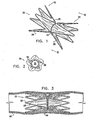
- FIG. 1 is a pictorial illustration of the device
- Fig. 2 is a cross-sectional view taken along a line II-II in Fig. 1 .
- Device 20 is adapted for use particularly in restricting blood flow through the coronary sinus, as desoribed in the above-mentioned PCT Publication WO 01/72239 .
- devices in accordance with the principles of the present invention may be implanted elsewhere in the vascular system, as well as in other body passages.
- embodiments of the present invention are described hereinbelow with reference to implantation of flow-constricting devices in blood vessels, such as the coronary sinus.
- Device 20 comprises ring elements 22 and 24, each of which comprises a resilient framework 26.
- Each framework defines a generally-cylindrical shape, although this shape is distorted by the mechanical constraints of the device, as described below. Therefore, the cylinders tend to widen at the ends of device 20 and narrow toward the middle, as shown in Fig. 1 .
- framework 26 comprises a wire or thin rod, which is bent into a serpentine shape.
- the framework comprises an elastic material, which may be compressed or otherwise bent, but then returns to its original shape, as shown in the figure.
- super-elastic materials such as Nitinol, are useful for this purpose.
- the framework may comprise a resilient, deformable material, such as a suitable metal or plastic.
- each framework 26 may comprise a mesh or coil, as is known in the art.
- resilient as used herein means that once device 20 is deployed within a body passage, framework 26 has sufficient mechanical strength to withstand normal forces exerted by the wall of the passage and by fluid flow within the passage, in the manner of stents known in the art.
- Ring elements 22 and 24 are fixed to a flexible sleeve 28, which has a generally tubular form.
- sleeve 28 comprises a biocompatible fabric, such as Gore-Tex or Dacron, which is stitched or otherwise fastened to framework 26.
- other sleeve materials may be used, such as thin plastic or rubber materials.
- the sleeve is fixed to the ring elements in such a way as to form a lumen 32 ( Fig. 2 ) through device 20.
- the sleeve is supported at each end of the lumen by one of the ring elements, while leaving a longitudinal gap in the sleeve, typically several millimeters long, between the inner ends of the two ring elements. While the ring elements themselves are relatively stiff (due to the resilience of framework 26); device 20 can be bent and deformed freely within the gap region of the sleeve.
- a constricting element 30 is fitted around sleeve 28 within the gap region. As can be seen in Fig. 2 , the effect of this constricting element is to reduce the diameter of lumen 32 to a predetermined size, less than the expanded diameter of ring elements 22 and 24.
- Constricting element 30 may simply comprise a thread, which is tied around the sleeve, or it may alternatively comprise a closed ring, made of plastic or metal. A constricting ring of this latter type is shown in Fig. 9A and described hereinbelow with reference thereto.
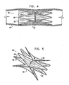
- Fig. 3 is a schematic side view of device 20 after implantation inside a blood vessel 40.
- device 20 is passed through the vascular system to the appropriate location (such as the coronary sinus), using a suitable percutaneous catheter (not shown in the figures). Suitable methods of catheterization for this purpose are known in the art.
- device 20 is compressed radially, so that its outer diameter is substantially smaller than the blood vessels through which it must pass.
- device 20 is able to bend freely in the area of the gap between ring elements 22 and 24, where constricting element 30 is located. This bending capability generally makes it easier for the physician operating the. catheter to pass the device through bends in the blood vessels.
- device 20 Upon reaching the desired location in blood vessel 40, device 20 is released from the catheter.
- framework 26 is made of an elastic material, such as Nitinol, the device will expand by itself, due to its own elasticity, as soon as it is released.
- framework 26 comprises a malleable material, a balloon may be inflated within each of ring elements 22 and 24, or other means known in the art may be used, in order to expand the framework.
- the above-mentioned PCT publication describes special types of balloons that may be used for this purpose.
- the serpentine shape of framework 26 creates elongated "fingers" that protrude at the ends of device 20.
- Device 20 may be left in place indefinitely, in substantially the form shown in Fig. 3 .
- Fig. 4 is a schematic side view of an implantable device 50 after implantation inside blood vessel 40, in accordance with another embodiment of the present invention.
- Blood in vessel 40 is assumed to flow from left to right in the view of the figure.
- Device 50 is substantially identical to device 20, as described above, except for the shape of sleeve 28.
- sleeve 28 is trimmed so that the ends of the sleeve have the same general shape as the "fingers" of framework 26.
- sleeve 28 is trimmed to a generally straight edge at the upstream (left) end of the device, covering the interstices between the fingers, as well as the fingers themselves.
- the straight upstream edge can be useful in reducing blood leakage around the sides of the device, thus providing more complete and reliable flow restriction.
- the uneven shape of the sleeve is maintained on the downstream edge, in order to anchor device 50 securely to the walls of vessel 40 against the pressure exerted by the blood flow in the vessel.
- sleeve 28 may be cut in other configurations, as mandated by medical and mechanical considerations.
- Fig. 5 is a schematic, pictorial view of an implantable device 60 in accordance with still another embodiment of the present invention.
- Device 60 is also substantially similar to device 20, as described above, except for the addition of longitudinal support members 62 and 65.
- the support members join ring elements 22 and 24 together and thus enhance the mechanical strength and stability of device 60.
- two longitudinal support members are shown in Fig. 5 , greater or smaller numbers of supports members may be used in like fashion. Note, however, that in the gap between the ring elements, sleeve 28 is detached from the support members, so that the diameter of lumen 32 can still be reduced by constricting element 30.
- Figs. 6A and 6B are schematic side views of a catheter 70, in a cutaway view, which is used to deliver device 20 to a target position in blood vessel 40 in accordance with an embodiment of the present invention.
- catheter 70 has a tubular outer shell 72 and a central lumen 74. Prior to delivery, device 20 is held inside shell 70, with lumen 74 passing through lumen 32 of device 20.
- a distal end 76 of shell 72 has a roughly conical shape, and has a small exit aperture 78 surrounding lumen 32.
- an operator threads a guide wire 80 through a part of the patient's vascular system to the target position, as is known in the art.
- the guide wire may be passed through the jugular vein into the coronary sinus. Once the guide wire is in place, the operator slides lumpen 74 over the guide wire, and thus guides distal end 76 of catheter 70 to the target position.
- a contrast medium may be injected through lumen 74 or through another, parallel lumen (not shown) to aid the operator in visualizing vessel 40 during the procedure using a fluoroscope, as is known in the art.
- distal end 76 When distal end 76 has reached the target position, the operator uses an ejector 82 to push device 20 out through aperture 78 in the distal end of the catheter.
- Distal end 76 in this embodiment is made of a material that is sufficiently elastic so that the aperture opens freely to the diameter of device 20. Once the device is ejected, it expands to the diameter of vessel 40, as shown in Fig. 3 , and anchors itself in place, The operator then withdraws catheter 70, and distal end 76 contracts back roughly to its original form.
- Figs. 7A and 7B are schematic side views of another catheter 90, which is used to deliver device 20 in accordance with an alternative embodiment of the present invention.
- Fig. 7A shows the catheter before delivery of device 20, while Fig. 7B , shows the catheter after, the delivery.
- distal end 76 comprises a thin sheath, which tears open as ejector 82 pushes the device out of the catheter.
- the distal end is scored along lines 92, so that as device 20 is ejected, the distal end tears cleanly, in a predictable fashion. Once device 20. has been ejected, the distal end may remain open where it has torn, but the open distal does not interfere with withdrawal of catheter 90 along wire 80.
- Figs. 8A, 8B and 8C are schematic side views of a catheter 100 for delivering device 20 in accordance with yet another embodiment of the present invention.
- the distal end 76 has an aperture 102 that is large enough to accommodate the (compressed) diameter of device 20 when the device is ejected from the catheter.
- the aperture is closed by a distended portion 104 of a lumen 106 that passes through the catheter, as shown in Fig. 8A .
- the lumen is typically used, to accommodate a guide wire and/or to inject contrast medium, as described above.
- Distended portion 104 is made of a flexible material, which may be either elastic or malleable, and is shaped so as to plug aperture 102.
- lumen 106 is advanced (and/or catheter 100 is withdrawn) so as to open aperture 102, as shown in Fig. 8B .
- Ejector 82 then pushes device 20 out through the aperture.
- portion 104 is sufficiently flexible so that as the narrow, gap region of lumen 32 through device 20 passes over it, portion 104 closes down so that lumen 32 can slide over it.
- portion 104 resumes its previous shape, and lumen 106 may be pulled back in the proximal direction in order to close aperture 102.
- Catheter 100 is then withdrawn from the body.
- Fig. 9A is a schematic, pictorial illustration of a constricting ring 120 in accordance with an embodiment of the present invention.
- This ring maybe used as a constricting element in device 20, taking the place of element 30 shown in the preceding figures.
- Ring 120 comprises a flexible, elastic wire 122.
- wire 122 may comprise a super-elastic material, such as Nitinol.
- Wire 122 is formed with multiple bends, typically in a serpentine pattern, as shown in Fig. 9A . Some of the bends are closed bends 124, at which the wire segments on opposing sides of the bend are fixed together thus narrowing the overall circumference of ring 120.
- the narrowed circumference of the ring constricts the diameter of lumen 32, as shown in Figs. 1 and 2 .
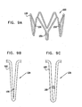
- Figs. 9B and 9C are schematic, detail views of one of closed bends 124 in ring 120 in accordance with two exemplary embodiments of the present invention.
- the opposing segments of wire 122 are pulled together and then fastened by welding, glue or other means, at a fastening point 126.
- Laser micro-welding as is known in the art, may be used for this purpose.
- a connecting element 128, such as a miniature ring is welded or otherwise fastened in place between the segments of wire on either side of the bend.
- bends 124 are typically closed weakly enough so that the fastening points or connecting elements will break open under outward radial pressure.
- Fig. 10 is a schematic, pictorial illustration of ring 120 following opening of closed bends 124 in accordance with an embodiment of the present invention.
- the closed bends may be opened in situ, after device 20 has been implanted in a blood vessel.
- a balloon catheter may be inserted into lumen 32 of device 20, and the balloon may be inflated.with sufficient pressure to break open the fastening points of at least some of bends 124. Due to the elasticity of wire 122, ring 120 will then expand to the larger diameter shown in Fig. 10 , and lumen 32 will open up accordingly.
- This sort of procedure may be used, for example, to permit free flow of blood through vessel 40 when the constriction due to device 20 is no longer needed or desired.
- Fig. 11 is a schematic, detail view of a part of a stent 130.
- Stent 130 comprises a structure of struts 132 with intervening openings 134. Some of the openings are bridged by narrow connecting pieces 136.
- Stent 130 is initially collapsed and crimped over a balloon for insertion into the target blood vessel. Inflation of the balloon to a first, intermediate pressure causes the stent to expand radially outward, so that openings 134 between struts 132 open to the configuration shown in Fig. 11 . The balloon is then withdrawn.
- the stent may be used in this configuration, for example, to open a blocked artery or other body lumen.
- a balloon may once more be inserted inside stent 130 and inflated to a second, higher pressure. The balloon thus exerts an outward radial force on stent 130, causing one or more of connecting pieces 136 to break open.
- the diameter of stent 130 (and of the lumen it is supporting) is increased simply and safely.
- Catheters of the general types described above may be used to deliver not only device 20, but also other implantable devices as described hereinaboye and as are otherwise known in the art.
- catheters shown here provide convenient means for delivering implants, such implants may also be delivered by other means, both minimally invasive (typically percutaneous) and invasive (i.e., surgical).
- FIG. 12 schematically illustrates a method for constricting the diameter of a vascular structure without the use of sutures or a stent, in accordance with an alternative embodiment of the present invention.
- the example is illustrated here with reference to reducing the diameter of a coronary sinus 140 of a patient, although this method is also applicable to other vascular structures.
- a catheter 142 is inserted through a right atrium 144 of the patient into coronary sinus 140.
- the catheter is bent at its distal end, as shown in the figure, to permit convenient deployment of a constricting clip 146, as described below.
- Figs. 13A-C are schematic, sectional views of coronary sinus 140, taken along a line XIII-XIII in Fig. 12 , showing stages in the deployment of clip 146.
- Clip 146 typically comprises a super-elastic material, which is formed so that in its relaxed state, it has an approximately closed form, as shown in Fig. 13C , for example. During insertion of catheter 142 into the coronary sinus, however, clip 146 is compressed within the distal end of catheter 142, as shown in Fig. 13A .
- a deployment mechanism such as a pusher (not shown) inside the catheter, is actuated in order to advance clip 146 out of the distal end of the catheter.
- the clip opens up into the configuration shown in Fig. 13B .
- Ends 148 of the clip catch the tissue of coronary sinus 140 at two points that are spaced apart on the wall of the coronary sinus.
- the elasticity of clip 146 causes the ends of the clip to draw together as the clip is advanced further out of the catheter, as illustrated by arrows 150.
- ends 148 close in toward one another and pinch together the portion of the vascular tissue that is located between the clip ends.
- the result as seen in Fig. 13C , is that the effective diameter of coronary sinus 140 is reduced.
Landscapes
- Health & Medical Sciences (AREA)
- Engineering & Computer Science (AREA)
- Biomedical Technology (AREA)
- Cardiology (AREA)
- Oral & Maxillofacial Surgery (AREA)
- Transplantation (AREA)
- Heart & Thoracic Surgery (AREA)
- Vascular Medicine (AREA)
- Life Sciences & Earth Sciences (AREA)
- Animal Behavior & Ethology (AREA)
- General Health & Medical Sciences (AREA)
- Public Health (AREA)
- Veterinary Medicine (AREA)
- Gastroenterology & Hepatology (AREA)
- Pulmonology (AREA)
- Prostheses (AREA)
- Media Introduction/Drainage Providing Device (AREA)
Claims (18)
- Implant médical (20) comprenant:un premier et un deuxième élément annulaire(22, 24), chacun comprenant un cadre résilient (26) ayant une forme généralement cylindrique; le cadre résilient (26) comprenant un câble (122) plié en forme de serpentinun manchon tubulaire (28) fixé aux premier et deuxième éléments annulaires (22, 24) de sorte à retenir les éléments annulaires en alignement longitudinal réciproque, définissant ainsi une lumière (32) traversant les éléments annulaires, caractérisé en ce que les premier et deuxième éléments annulaires laissent un écart longitudinal entre les extrémités intérieures des deux éléments annulaires (22, 24) afin que les premier et deuxième éléments annulaires (22, 24) ne soient pas en contact direct l'un avec l'autre; etun élément constricteur (30, 120), adapté autour du manchon (28) au sein de la région de écart, a un emplacement intermédiaire entre les premier et deuxième éléments annulaires (22, 24) de sorte à réduire le diamètre de la lumière (32) à l'emplacement.
- Implant selon la revendication 1, dans lequel les éléments annulaires (22, 24) sont aptes à être insérés en forme radialement comprimée à travers un passage corporel à une position cible à l'intérieur du passage, et ensuite à se détendre radialement à la position cible afin d'ouvrir à travers celui-ci la lumière (32).
- Implant selon la revendication 2, dans lequel le cadre (26) comprend un matériel élastique, compressible pour fournir la forme radialement comprimée des éléments annulaires (22, 24), et qui se détend radialement lorsqu'il est relâché à la position cible.
- Implant selon la revendication 1, et comprenant un ou plusieurs éléments de support longitudinaux (62, 65), fixés au cadre (26) des premier et deuxième éléments annulaires (22, 24), le long du manchon (28), de sorte à joindre les premier et deuxième éléments annulaires ensemble.
- Implant selon la revendication 1, dans lequel le manchon (28) comprend un tissu.
- Implant selon la revendication 5, dans lequel le tissu est cousu au cadre (26) des premier et deuxième éléments annulaires (22, 24).
- Implant selon la revendication 1, dans lequel la lumière (32) traversant les premier et deuxième éléments annulaires (22, 24) a une première et une deuxième extrémité, et dans lequel le cadre (26) est configuré pour fournir des saillies allongées à l'une ou plusieurs des extrémités de la lumière (32).
- Implant selon la revendication 7, dans lequel le manchon (28) est coupé à l'une ou plusieurs des première et deuxième extrémités conformément aux saillies.
- Implant selon la revendication 8, dans lequel le manchon (28) est coupé à la première extrémité conformément aux saillies, tandis que le manchon (28) à la deuxième couvre autant les saillies que les interstices entre les saillies à la deuxième extrémité de la lumière (32).
- Implant selon l'une quelconque des revendications 1-9, dans lequel l'implant est apte à être implanté dans un sinus coronaire d'un patient, de sorte que le flux sanguin à travers le sinus coronaire soit inhibé par le diamètre réduit de la lumière (32).
- Implant selon l'une quelconque des revendications 1-9, dans lequel l'élément constricteur (30, 120) est apte à se détendre sous une force radiale extérieure de sorte à permettre au diamètre réduit de la lumière (32) d'augmenter.
- Implant selon la revendication 11, dans lequel l'élément constricteur (30, 120) comprend un câble élastique (122), ayant des pliures fermement serrées afin de fournir le diamètre réduit, et qui sont aptes à s'ouvrir sous la force radiale extérieure.
- Procédé pour produire un implant médical, comprenant de:fournir un premier et un deuxième élément annulaire (22, 24), chacun comprenant un cadre résilient (26) ayant une forme généralement cylindrique;fixer un manchon tubulaire (28) aux premier et deuxième éléments annulaires afin de retenir les éléments annulaires en alignement longitudinal réciproque, en définissant ainsi une lumière (32) traversant les éléments annulaires, et laisser un écart longitudinal entre les extrémités intérieures des deux éléments annulaires de sorte que les premier et deuxième éléments annulaires ne se trouvent pas en contact direct l'un avec l'autre; etadapter un élément constricteur (30, 120) autour du manchon (28) à la région de l'écart, à un emplacement intermédiaire entre les premier et deuxième éléments annulaires (22, 24) afin de réduire un diamètre de la lumière (32) à l'emplacement,le cadre résilient (26) étant fourni comprenant un câble (122) plié en forme de serpentin.
- Procédé selon la revendication 13, dans lequel la lumière (32) traversant les premier et deuxième éléments annulaires (22, 24) présente une première et une deuxième extrémité, et dans lequel la pliure du câble comprend de produire des saillies allongées du cadre (26) à l'une ou plusieurs des extrémités de la lumière (32).
- Procédé selon la revendication 13, et comprenant de fixer un ou plusieurs éléments de support longitudinaux (62, 65) au cadre (26) des premier et deuxième éléments annulaires (22, 24) le long du manchon (28), de sorte à joindre les premier et deuxième éléments annulaires (22, 24) ensemble.
- Procédé selon l'une quelconque des revendications 13-15, dans lequel la fixation du manchon (28) comprend de coudre un tissu au cadre (26) des premier et deuxième éléments annulaires (22, 24).
- Procédé selon l'une quelconque des revendications 13-15, dans lequel l'adaptation de l'élément constricteur (30, 120) comprend de configurer l'élément constricteur pour se détendre sous une force radiale extérieure de sorte à permettre au diamètre réduit de la lumière (32) d'augmenter.
- Procédé selon la revendication 17, dans lequel l'élément constricteur (30, 120) comprend un câble élastique (122), ayant des pliures (124) fermement serrées afin de fournir le diamètre réduit, et qui sont aptes à s'ouvrir sous la force radiale extérieure.
Priority Applications (2)
| Application Number | Priority Date | Filing Date | Title |
|---|---|---|---|
| EP14164803.0A EP2756821B1 (fr) | 2003-11-19 | 2004-11-18 | Implant vasculaire |
| EP15186450.1A EP3020377B1 (fr) | 2003-11-19 | 2004-11-18 | Dispositif pour delivrer une prothese endoluminale |
Applications Claiming Priority (2)
| Application Number | Priority Date | Filing Date | Title |
|---|---|---|---|
| IL15896003A IL158960A0 (en) | 2003-11-19 | 2003-11-19 | Vascular implant |
| PCT/IL2004/001063 WO2005048871A2 (fr) | 2003-11-19 | 2004-11-18 | Implant vasculaire |
Related Child Applications (3)
| Application Number | Title | Priority Date | Filing Date |
|---|---|---|---|
| EP15186450.1A Division EP3020377B1 (fr) | 2003-11-19 | 2004-11-18 | Dispositif pour delivrer une prothese endoluminale |
| EP14164803.0A Division-Into EP2756821B1 (fr) | 2003-11-19 | 2004-11-18 | Implant vasculaire |
| EP14164803.0A Division EP2756821B1 (fr) | 2003-11-19 | 2004-11-18 | Implant vasculaire |
Publications (3)
| Publication Number | Publication Date |
|---|---|
| EP1689324A2 EP1689324A2 (fr) | 2006-08-16 |
| EP1689324A4 EP1689324A4 (fr) | 2008-04-09 |
| EP1689324B1 true EP1689324B1 (fr) | 2014-10-15 |
Family
ID=34044288
Family Applications (3)
| Application Number | Title | Priority Date | Filing Date |
|---|---|---|---|
| EP15186450.1A Expired - Lifetime EP3020377B1 (fr) | 2003-11-19 | 2004-11-18 | Dispositif pour delivrer une prothese endoluminale |
| EP04799370.4A Expired - Lifetime EP1689324B1 (fr) | 2003-11-19 | 2004-11-18 | Implant vasculaire |
| EP14164803.0A Expired - Lifetime EP2756821B1 (fr) | 2003-11-19 | 2004-11-18 | Implant vasculaire |
Family Applications Before (1)
| Application Number | Title | Priority Date | Filing Date |
|---|---|---|---|
| EP15186450.1A Expired - Lifetime EP3020377B1 (fr) | 2003-11-19 | 2004-11-18 | Dispositif pour delivrer une prothese endoluminale |
Family Applications After (1)
| Application Number | Title | Priority Date | Filing Date |
|---|---|---|---|
| EP14164803.0A Expired - Lifetime EP2756821B1 (fr) | 2003-11-19 | 2004-11-18 | Implant vasculaire |
Country Status (9)
| Country | Link |
|---|---|
| US (7) | US20070027525A1 (fr) |
| EP (3) | EP3020377B1 (fr) |
| JP (1) | JP5154799B2 (fr) |
| CN (1) | CN1901851A (fr) |
| AU (1) | AU2004290990A1 (fr) |
| CA (3) | CA2823472C (fr) |
| IL (2) | IL158960A0 (fr) |
| MX (1) | MXPA06005673A (fr) |
| WO (1) | WO2005048871A2 (fr) |
Cited By (1)
| Publication number | Priority date | Publication date | Assignee | Title |
|---|---|---|---|---|
| US11564818B2 (en) | 2003-11-19 | 2023-01-31 | Neovase Medical Ltd. | Vascular implant |
Families Citing this family (131)
| Publication number | Priority date | Publication date | Assignee | Title |
|---|---|---|---|---|
| US6391048B1 (en) | 2000-01-05 | 2002-05-21 | Integrated Vascular Systems, Inc. | Integrated vascular device with puncture site closure component and sealant and methods of use |
| US6461364B1 (en) | 2000-01-05 | 2002-10-08 | Integrated Vascular Systems, Inc. | Vascular sheath with bioabsorbable puncture site closure apparatus and methods of use |
| US9579091B2 (en) | 2000-01-05 | 2017-02-28 | Integrated Vascular Systems, Inc. | Closure system and methods of use |
| US8758400B2 (en) | 2000-01-05 | 2014-06-24 | Integrated Vascular Systems, Inc. | Closure system and methods of use |
| US7842068B2 (en) | 2000-12-07 | 2010-11-30 | Integrated Vascular Systems, Inc. | Apparatus and methods for providing tactile feedback while delivering a closure device |
| JP2004508092A (ja) | 2000-09-08 | 2004-03-18 | コールマン ジェイムス イー | 外科用ステープラ |
| US6626918B1 (en) * | 2000-10-06 | 2003-09-30 | Medical Technology Group | Apparatus and methods for positioning a vascular sheath |
| US7905900B2 (en) | 2003-01-30 | 2011-03-15 | Integrated Vascular Systems, Inc. | Clip applier and methods of use |
| US7211101B2 (en) | 2000-12-07 | 2007-05-01 | Abbott Vascular Devices | Methods for manufacturing a clip and clip |
| US6623510B2 (en) | 2000-12-07 | 2003-09-23 | Integrated Vascular Systems, Inc. | Closure device and methods for making and using them |
| US8690910B2 (en) | 2000-12-07 | 2014-04-08 | Integrated Vascular Systems, Inc. | Closure device and methods for making and using them |
| IES20010547A2 (en) | 2001-06-07 | 2002-12-11 | Christy Cummins | Surgical Staple |
| JP4398244B2 (ja) * | 2001-10-04 | 2010-01-13 | ネオヴァスク メディカル リミテッド | 流量減少インプラント |
| US6749621B2 (en) | 2002-02-21 | 2004-06-15 | Integrated Vascular Systems, Inc. | Sheath apparatus and methods for delivering a closure device |
| CA2488688A1 (fr) | 2002-06-04 | 2003-12-11 | Christy Cummins | Clip de fermeture pour vaisseau sanguin et dispositif d'apport |
| US8398656B2 (en) | 2003-01-30 | 2013-03-19 | Integrated Vascular Systems, Inc. | Clip applier and methods of use |
| US8202293B2 (en) | 2003-01-30 | 2012-06-19 | Integrated Vascular Systems, Inc. | Clip applier and methods of use |
| US8758398B2 (en) | 2006-09-08 | 2014-06-24 | Integrated Vascular Systems, Inc. | Apparatus and method for delivering a closure element |
| US8821534B2 (en) | 2010-12-06 | 2014-09-02 | Integrated Vascular Systems, Inc. | Clip applier having improved hemostasis and methods of use |
| US8905937B2 (en) | 2009-02-26 | 2014-12-09 | Integrated Vascular Systems, Inc. | Methods and apparatus for locating a surface of a body lumen |
| ES2725721T3 (es) | 2004-02-03 | 2019-09-26 | V Wave Ltd | Dispositivo y método para controlar la presión in vivo |
| IES20040368A2 (en) | 2004-05-25 | 2005-11-30 | James E Coleman | Surgical stapler |
| US8926633B2 (en) | 2005-06-24 | 2015-01-06 | Abbott Laboratories | Apparatus and method for delivering a closure element |
| US8313497B2 (en) | 2005-07-01 | 2012-11-20 | Abbott Laboratories | Clip applier and methods of use |
| WO2007083288A2 (fr) | 2006-01-23 | 2007-07-26 | Atria Medical Inc. | Dispositif d’ancre cardiaque |
| US8808310B2 (en) | 2006-04-20 | 2014-08-19 | Integrated Vascular Systems, Inc. | Resettable clip applier and reset tools |
| US8556930B2 (en) | 2006-06-28 | 2013-10-15 | Abbott Laboratories | Vessel closure device |
| US20240032905A1 (en) * | 2006-11-07 | 2024-02-01 | Corvia Medical, Inc. | Devices and methods for the treatment of heart failure |
| EP2106250B1 (fr) * | 2007-01-25 | 2020-04-01 | Boston Scientific Limited | Endoscope avec endoprothèse préchargée ou pré-chargeable |
| WO2009018248A1 (fr) * | 2007-07-30 | 2009-02-05 | Audubon Technologies, Llc | Dispositif pour maintenir des ostium de sinus paranasaux de patient |
| CN101152111B (zh) * | 2007-09-07 | 2010-07-14 | 中国人民解放军第四军医大学第一附属医院 | 用于肺动脉高压外科治疗的肺动脉缩窄支架 |
| US8893947B2 (en) | 2007-12-17 | 2014-11-25 | Abbott Laboratories | Clip applier and methods of use |
| US20090157101A1 (en) * | 2007-12-17 | 2009-06-18 | Abbott Laboratories | Tissue closure system and methods of use |
| US7841502B2 (en) | 2007-12-18 | 2010-11-30 | Abbott Laboratories | Modular clip applier |
| US8992593B2 (en) * | 2007-12-26 | 2015-03-31 | Cook Medical Technologies Llc | Apparatus and methods for deployment of a modular stent-graft system |
| GB2475494B (en) | 2009-11-18 | 2011-11-23 | Cook William Europ | Stent graft and introducer assembly |
| US9226813B2 (en) * | 2007-12-26 | 2016-01-05 | Cook Medical Technologies Llc | Low profile non-symmetrical stent |
| US9180030B2 (en) | 2007-12-26 | 2015-11-10 | Cook Medical Technologies Llc | Low profile non-symmetrical stent |
| GB2476451A (en) * | 2009-11-19 | 2011-06-29 | Cook William Europ | Stent Graft |
| US8574284B2 (en) | 2007-12-26 | 2013-11-05 | Cook Medical Technologies Llc | Low profile non-symmetrical bare alignment stents with graft |
| US8728145B2 (en) | 2008-12-11 | 2014-05-20 | Cook Medical Technologies Llc | Low profile non-symmetrical stents and stent-grafts |
| US9282965B2 (en) | 2008-05-16 | 2016-03-15 | Abbott Laboratories | Apparatus and methods for engaging tissue |
| CN102098988B (zh) * | 2008-09-30 | 2014-05-14 | 泰尔茂株式会社 | 支架输送系统 |
| US9241696B2 (en) | 2008-10-30 | 2016-01-26 | Abbott Vascular Inc. | Closure device |
| US8858594B2 (en) | 2008-12-22 | 2014-10-14 | Abbott Laboratories | Curved closure device |
| US20110218568A1 (en) * | 2009-01-09 | 2011-09-08 | Voss Laveille K | Vessel closure devices, systems, and methods |
| US20100179589A1 (en) | 2009-01-09 | 2010-07-15 | Abbott Vascular Inc. | Rapidly eroding anchor |
| US9173644B2 (en) * | 2009-01-09 | 2015-11-03 | Abbott Vascular Inc. | Closure devices, systems, and methods |
| US9414820B2 (en) | 2009-01-09 | 2016-08-16 | Abbott Vascular Inc. | Closure devices, systems, and methods |
| US9089311B2 (en) | 2009-01-09 | 2015-07-28 | Abbott Vascular Inc. | Vessel closure devices and methods |
| US9486191B2 (en) | 2009-01-09 | 2016-11-08 | Abbott Vascular, Inc. | Closure devices |
| US20100185234A1 (en) | 2009-01-16 | 2010-07-22 | Abbott Vascular Inc. | Closure devices, systems, and methods |
| US9034034B2 (en) | 2010-12-22 | 2015-05-19 | V-Wave Ltd. | Devices for reducing left atrial pressure, and methods of making and using same |
| WO2010128501A1 (fr) | 2009-05-04 | 2010-11-11 | V-Wave Ltd. | Dispositif et procédé permettant de réguler la pression à l'intérieur d'une cavité cardiaque |
| US12186176B2 (en) | 2009-05-04 | 2025-01-07 | V-Wave Ltd. | Shunt for redistributing atrial blood volume |
| US12453626B2 (en) | 2009-05-04 | 2025-10-28 | V-Wave Ltd. | Shunt for redistributing atrial blood volume |
| US20110054492A1 (en) | 2009-08-26 | 2011-03-03 | Abbott Laboratories | Medical device for repairing a fistula |
| US9757263B2 (en) * | 2009-11-18 | 2017-09-12 | Cook Medical Technologies Llc | Stent graft and introducer assembly |
| US8870950B2 (en) | 2009-12-08 | 2014-10-28 | Mitral Tech Ltd. | Rotation-based anchoring of an implant |
| US20110224785A1 (en) | 2010-03-10 | 2011-09-15 | Hacohen Gil | Prosthetic mitral valve with tissue anchors |
| US11653910B2 (en) | 2010-07-21 | 2023-05-23 | Cardiovalve Ltd. | Helical anchor implantation |
| US8992604B2 (en) | 2010-07-21 | 2015-03-31 | Mitraltech Ltd. | Techniques for percutaneous mitral valve replacement and sealing |
| US9132009B2 (en) | 2010-07-21 | 2015-09-15 | Mitraltech Ltd. | Guide wires with commissural anchors to advance a prosthetic valve |
| US9763657B2 (en) | 2010-07-21 | 2017-09-19 | Mitraltech Ltd. | Techniques for percutaneous mitral valve replacement and sealing |
| US8758399B2 (en) | 2010-08-02 | 2014-06-24 | Abbott Cardiovascular Systems, Inc. | Expandable bioabsorbable plug apparatus and method |
| US8603116B2 (en) | 2010-08-04 | 2013-12-10 | Abbott Cardiovascular Systems, Inc. | Closure device with long tines |
| US8617184B2 (en) | 2011-02-15 | 2013-12-31 | Abbott Cardiovascular Systems, Inc. | Vessel closure system |
| US9149276B2 (en) | 2011-03-21 | 2015-10-06 | Abbott Cardiovascular Systems, Inc. | Clip and deployment apparatus for tissue closure |
| US8556932B2 (en) | 2011-05-19 | 2013-10-15 | Abbott Cardiovascular Systems, Inc. | Collapsible plug for tissue closure |
| US11135054B2 (en) | 2011-07-28 | 2021-10-05 | V-Wave Ltd. | Interatrial shunts having biodegradable material, and methods of making and using same |
| WO2013021374A2 (fr) | 2011-08-05 | 2013-02-14 | Mitraltech Ltd. | Techniques pour le remplacement et la fixation percutanés d'une valvule mitrale |
| US8852272B2 (en) | 2011-08-05 | 2014-10-07 | Mitraltech Ltd. | Techniques for percutaneous mitral valve replacement and sealing |
| US20140324164A1 (en) | 2011-08-05 | 2014-10-30 | Mitraltech Ltd. | Techniques for percutaneous mitral valve replacement and sealing |
| WO2013021375A2 (fr) | 2011-08-05 | 2013-02-14 | Mitraltech Ltd. | Remplacement et fixation percutanés d'une valvule mitrale |
| US9332976B2 (en) * | 2011-11-30 | 2016-05-10 | Abbott Cardiovascular Systems, Inc. | Tissue closure device |
| EP2674173A1 (fr) * | 2012-06-15 | 2013-12-18 | Commissariat A L'energie Atomique Et Aux Energies Alternatives | Matériau implantable greffé avec une cellule antiprolifératives et/ou film antibactérien et son procédé de greffage |
| US9364209B2 (en) | 2012-12-21 | 2016-06-14 | Abbott Cardiovascular Systems, Inc. | Articulating suturing device |
| US20150351906A1 (en) | 2013-01-24 | 2015-12-10 | Mitraltech Ltd. | Ventricularly-anchored prosthetic valves |
| CN104269018B (zh) * | 2013-05-10 | 2016-06-15 | 海安华厚电子科技有限公司 | 电视机的多功能监控系统 |
| CN105555204B (zh) | 2013-05-21 | 2018-07-10 | V-波有限责任公司 | 用于递送减小左房压力的装置的设备 |
| US10667931B2 (en) * | 2014-07-20 | 2020-06-02 | Restore Medical Ltd. | Pulmonary artery implant apparatus and methods of use thereof |
| WO2016016899A1 (fr) | 2014-07-30 | 2016-02-04 | Mitraltech Ltd. | Prothèse valvulaire articulable |
| CA2973940C (fr) | 2015-02-05 | 2022-08-23 | Mitraltech Ltd. | Valve prothetique avec cadres coulissant axialement |
| US9974651B2 (en) | 2015-02-05 | 2018-05-22 | Mitral Tech Ltd. | Prosthetic valve with axially-sliding frames |
| EP3291773B1 (fr) | 2015-05-07 | 2026-01-07 | The Medical Research, Infrastructure, And Health Services Fund Of The Tel Aviv Medical Center | Shunts interauriculaires temporaires |
| DE102015116628A1 (de) | 2015-09-30 | 2017-03-30 | Möller Medical Gmbh | Vorrichtung zum Einführen eines Stents in ein Körpergefäß |
| US10531866B2 (en) | 2016-02-16 | 2020-01-14 | Cardiovalve Ltd. | Techniques for providing a replacement valve and transseptal communication |
| US10835394B2 (en) | 2016-05-31 | 2020-11-17 | V-Wave, Ltd. | Systems and methods for making encapsulated hourglass shaped stents |
| US20170340460A1 (en) | 2016-05-31 | 2017-11-30 | V-Wave Ltd. | Systems and methods for making encapsulated hourglass shaped stents |
| GB201613219D0 (en) | 2016-08-01 | 2016-09-14 | Mitraltech Ltd | Minimally-invasive delivery systems |
| WO2018029680A1 (fr) | 2016-08-10 | 2018-02-15 | Mitraltech Ltd. | Valve prothétique avec cadres concentriques. |
| USD800908S1 (en) | 2016-08-10 | 2017-10-24 | Mitraltech Ltd. | Prosthetic valve element |
| US11771434B2 (en) | 2016-09-28 | 2023-10-03 | Restore Medical Ltd. | Artery medical apparatus and methods of use thereof |
| US11291807B2 (en) | 2017-03-03 | 2022-04-05 | V-Wave Ltd. | Asymmetric shunt for redistributing atrial blood volume |
| CA3054891A1 (fr) | 2017-03-03 | 2018-09-07 | V-Wave Ltd. | Derivation de redistribution du volume sanguin atrial |
| CN107174386A (zh) * | 2017-04-27 | 2017-09-19 | 广州启骏生物科技有限公司 | 一种治疗肺动脉高压的装置 |
| CN110891522B (zh) | 2017-06-02 | 2021-12-14 | 内弗罗尼公司 | 体腔中的流动调节 |
| CN110691554B (zh) | 2017-06-05 | 2022-11-01 | 恢复医疗有限公司 | 双壁固定长度的支架状设备及其使用方法 |
| US10575948B2 (en) | 2017-08-03 | 2020-03-03 | Cardiovalve Ltd. | Prosthetic heart valve |
| US10537426B2 (en) | 2017-08-03 | 2020-01-21 | Cardiovalve Ltd. | Prosthetic heart valve |
| US11793633B2 (en) | 2017-08-03 | 2023-10-24 | Cardiovalve Ltd. | Prosthetic heart valve |
| US12064347B2 (en) | 2017-08-03 | 2024-08-20 | Cardiovalve Ltd. | Prosthetic heart valve |
| US11246704B2 (en) | 2017-08-03 | 2022-02-15 | Cardiovalve Ltd. | Prosthetic heart valve |
| US10888421B2 (en) | 2017-09-19 | 2021-01-12 | Cardiovalve Ltd. | Prosthetic heart valve with pouch |
| US10350095B2 (en) | 2017-08-17 | 2019-07-16 | Incubar, LLC | Prosthetic vascular valve and methods associated therewith |
| US12458493B2 (en) | 2017-09-19 | 2025-11-04 | Cardiovalve Ltd. | Prosthetic heart valve and delivery systems and methods |
| US10595874B2 (en) | 2017-09-21 | 2020-03-24 | W. L. Gore & Associates, Inc. | Multiple inflation endovascular medical device |
| GB201720803D0 (en) | 2017-12-13 | 2018-01-24 | Mitraltech Ltd | Prosthetic Valve and delivery tool therefor |
| GB201800399D0 (en) | 2018-01-10 | 2018-02-21 | Mitraltech Ltd | Temperature-control during crimping of an implant |
| WO2019142152A1 (fr) | 2018-01-20 | 2019-07-25 | V-Wave Ltd. | Dispositifs et procédés pour fournir un passage entre des chambres cardiaques |
| US11458287B2 (en) | 2018-01-20 | 2022-10-04 | V-Wave Ltd. | Devices with dimensions that can be reduced and increased in vivo, and methods of making and using the same |
| US10898698B1 (en) | 2020-05-04 | 2021-01-26 | V-Wave Ltd. | Devices with dimensions that can be reduced and increased in vivo, and methods of making and using the same |
| CN111787871B (zh) * | 2018-03-29 | 2023-12-12 | 波士顿科学国际有限公司 | 流量控制阀 |
| WO2019221971A1 (fr) | 2018-05-12 | 2019-11-21 | Venacore Inc. | Régulation de la vitesse du flux sanguin vers l'oreillette droite |
| EP3886760A1 (fr) * | 2018-11-26 | 2021-10-06 | Nephronyx Ltd. | Dispositifs de modification d'écoulement dans des lumières corporelles |
| CN113195038B (zh) | 2018-12-11 | 2025-12-30 | 瑞普医药有限公司 | 用于调节体腔中的血流量的系统、装置以及方法 |
| CN113891686B (zh) | 2019-01-23 | 2024-12-27 | 冲击波医疗公司 | 具有覆盖物的流改变装置 |
| EP3914198A4 (fr) * | 2019-01-24 | 2022-10-12 | Neovasc Medical Ltd. | Implants modifiant le flux |
| US12226602B2 (en) | 2019-04-03 | 2025-02-18 | V-Wave Ltd. | Systems for delivering implantable devices across an atrial septum |
| US11612385B2 (en) | 2019-04-03 | 2023-03-28 | V-Wave Ltd. | Systems and methods for delivering implantable devices across an atrial septum |
| US11865282B2 (en) | 2019-05-20 | 2024-01-09 | V-Wave Ltd. | Systems and methods for creating an interatrial shunt |
| US12599756B2 (en) | 2020-05-04 | 2026-04-14 | V-Wave Ltd. | Devices with dimensions that can be reduced and increased In Vivo |
| CN115942919A (zh) | 2020-05-28 | 2023-04-07 | 内弗罗尼公司 | 用于修改体腔中的流动的急性和慢性装置以及其使用方法 |
| CN112022261B (zh) * | 2020-08-24 | 2022-03-18 | 上海长海医院 | 一种异常血管通道封堵装置 |
| US11234702B1 (en) | 2020-11-13 | 2022-02-01 | V-Wave Ltd. | Interatrial shunt having physiologic sensor |
| US12357459B2 (en) | 2020-12-03 | 2025-07-15 | Cardiovalve Ltd. | Transluminal delivery system |
| JPWO2023037859A1 (fr) * | 2021-09-08 | 2023-03-16 | ||
| US12588910B1 (en) | 2021-11-08 | 2026-03-31 | VahatiCor, Inc. | Vascular flow restriction devices and related systems and methods |
| CN119343093A (zh) | 2022-04-14 | 2025-01-21 | V-波有限责任公司 | 具有扩张颈部区域的房间分流器 |
| CN115783502A (zh) * | 2022-10-25 | 2023-03-14 | 上海心玮医疗科技股份有限公司 | 一种颅内植入物包装保护装置 |
| IL327576A (en) | 2023-10-18 | 2026-05-01 | V Wave Ltd | Hybrid devices with adjustable dimensions within the body and methods of manufacturing the same |
Family Cites Families (137)
| Publication number | Priority date | Publication date | Assignee | Title |
|---|---|---|---|---|
| GB1264471A (fr) | 1968-01-12 | 1972-02-23 | ||
| GB1315844A (en) | 1970-05-12 | 1973-05-02 | Nat Res Dev | Prosthetic cardiac valve |
| US3739402A (en) | 1970-10-15 | 1973-06-19 | Cutter Lab | Bicuspid fascia lata valve |
| AR206762A1 (es) | 1976-01-01 | 1976-08-13 | Pisanu A | Bioprotesis de bajo perfil derivada de la valvula aortica heterologa de porcino |
| GB1603634A (en) | 1977-05-05 | 1981-11-25 | Nat Res Dev | Prosthetic valves |
| US4340977A (en) | 1980-09-19 | 1982-07-27 | Brownlee Richard T | Catenary mitral valve replacement |
| US4339831A (en) | 1981-03-27 | 1982-07-20 | Medtronic, Inc. | Dynamic annulus heart valve and reconstruction ring |
| US4470157A (en) | 1981-04-27 | 1984-09-11 | Love Jack W | Tricuspid prosthetic tissue heart valve |
| US4865600A (en) | 1981-08-25 | 1989-09-12 | Baxter International Inc. | Mitral valve holder |
| ATE21330T1 (de) | 1982-01-20 | 1986-08-15 | Martin Morris Black | Kuenstliche herzklappen. |
| US4580468A (en) | 1984-06-20 | 1986-04-08 | Cox Terrence D | Pipe wrench |
| US4580568A (en) * | 1984-10-01 | 1986-04-08 | Cook, Incorporated | Percutaneous endovascular stent and method for insertion thereof |
| GB9012716D0 (en) | 1990-06-07 | 1990-08-01 | Frater Robert W M | Mitral heart valve replacements |
| FR2688401B1 (fr) * | 1992-03-12 | 1998-02-27 | Thierry Richard | Endoprothese expansible pour organe tubulaire humain ou animal, et outil de mise en place. |
| JP2660101B2 (ja) * | 1992-05-08 | 1997-10-08 | シュナイダー・(ユーエスエイ)・インコーポレーテッド | 食道ステント及び運搬具 |
| WO1994023786A1 (fr) * | 1993-04-13 | 1994-10-27 | Boston Scientific Corporation | Dispositif d'application d'une prothese |
| DE4334140C2 (de) * | 1993-10-07 | 1996-04-18 | Angiomed Ag | Stent und Vorrichtung mit Stent |
| US5824041A (en) * | 1994-06-08 | 1998-10-20 | Medtronic, Inc. | Apparatus and methods for placement and repositioning of intraluminal prostheses |
| US5593424A (en) * | 1994-08-10 | 1997-01-14 | Segmed, Inc. | Apparatus and method for reducing and stabilizing the circumference of a vascular structure |
| US5647857A (en) * | 1995-03-16 | 1997-07-15 | Endotex Interventional Systems, Inc. | Protective intraluminal sheath |
| US5591195A (en) * | 1995-10-30 | 1997-01-07 | Taheri; Syde | Apparatus and method for engrafting a blood vessel |
| US5843158A (en) * | 1996-01-05 | 1998-12-01 | Medtronic, Inc. | Limited expansion endoluminal prostheses and methods for their use |
| WO1997025002A1 (fr) | 1996-01-05 | 1997-07-17 | Medtronic, Inc. | Protheses endoluminales expansibles |
| EP1066804B1 (fr) | 1996-03-05 | 2004-07-14 | Evysio Medical Devices Ulc | Stent extensible |
| WO1997036556A1 (fr) | 1996-03-29 | 1997-10-09 | WILLY RüSCH AG | Extenseur |
| DE19624948A1 (de) | 1996-06-24 | 1998-01-02 | Adiam Medizintechnik Gmbh & Co | Prothetische Herzklappe |
| DE19625202A1 (de) | 1996-06-24 | 1998-01-02 | Adiam Medizintechnik Gmbh & Co | Prothetische Mitral-Herzklappe |
| US5669919A (en) | 1996-08-16 | 1997-09-23 | Medtronic, Inc. | Annuloplasty system |
| US5868782A (en) | 1996-12-24 | 1999-02-09 | Global Therapeutics, Inc. | Radially expandable axially non-contracting surgical stent |
| EP0850607A1 (fr) | 1996-12-31 | 1998-07-01 | Cordis Corporation | Prothèse de valve pour implantation dans des canaux corporels |
| US6241757B1 (en) * | 1997-02-04 | 2001-06-05 | Solco Surgical Instrument Co., Ltd. | Stent for expanding body's lumen |
| CA2229685C (fr) * | 1997-02-27 | 2003-09-02 | Corvita Corporation | Endoprotheses endoluminales modulaires et methodes d'utilisation |
| US6042606A (en) | 1997-09-29 | 2000-03-28 | Cook Incorporated | Radially expandable non-axially contracting surgical stent |
| US6120534A (en) * | 1997-10-29 | 2000-09-19 | Ruiz; Carlos E. | Endoluminal prosthesis having adjustable constriction |
| US6099559A (en) | 1998-05-28 | 2000-08-08 | Medtronic Ave, Inc. | Endoluminal support assembly with capped ends |
| US6350277B1 (en) * | 1999-01-15 | 2002-02-26 | Scimed Life Systems, Inc. | Stents with temporary retaining bands |
| IT1312073B1 (it) * | 1999-04-14 | 2002-04-04 | Pietro Quaretti | Endoprotesi intraepatica. |
| US6270521B1 (en) * | 1999-05-21 | 2001-08-07 | Cordis Corporation | Stent delivery catheter system for primary stenting |
| US6790229B1 (en) | 1999-05-25 | 2004-09-14 | Eric Berreklouw | Fixing device, in particular for fixing to vascular wall tissue |
| US6312465B1 (en) | 1999-07-23 | 2001-11-06 | Sulzer Carbomedics Inc. | Heart valve prosthesis with a resiliently deformable retaining member |
| US6231561B1 (en) | 1999-09-20 | 2001-05-15 | Appriva Medical, Inc. | Method and apparatus for closing a body lumen |
| CA2391420C (fr) | 1999-11-11 | 2009-05-05 | Juergen Dorn | Dispositif de mise en place d'implant |
| US20070043435A1 (en) | 1999-11-17 | 2007-02-22 | Jacques Seguin | Non-cylindrical prosthetic valve system for transluminal delivery |
| US7018406B2 (en) | 1999-11-17 | 2006-03-28 | Corevalve Sa | Prosthetic valve for transluminal delivery |
| US6458153B1 (en) | 1999-12-31 | 2002-10-01 | Abps Venture One, Ltd. | Endoluminal cardiac and venous valve prostheses and methods of manufacture and delivery thereof |
| IL153753A0 (en) * | 2002-12-30 | 2003-07-06 | Neovasc Medical Ltd | Varying-diameter vascular implant and balloon |
| US6953476B1 (en) | 2000-03-27 | 2005-10-11 | Neovasc Medical Ltd. | Device and method for treating ischemic heart disease |
| US6520984B1 (en) | 2000-04-28 | 2003-02-18 | Cardiovasc, Inc. | Stent graft assembly and method |
| US6610088B1 (en) | 2000-05-03 | 2003-08-26 | Shlomo Gabbay | Biologically covered heart valve prosthesis |
| US6358277B1 (en) | 2000-06-21 | 2002-03-19 | The International Heart Institute Of Montana Foundation | Atrio-ventricular valvular device |
| US7510572B2 (en) | 2000-09-12 | 2009-03-31 | Shlomo Gabbay | Implantation system for delivery of a heart valve prosthesis |
| US20020193863A1 (en) | 2000-09-18 | 2002-12-19 | Endotex Interventional Systems, Inc. | Apparatus for delivering endoluminal prosthesis and methods for preparing such apparatus for delivery |
| DE10046550A1 (de) | 2000-09-19 | 2002-03-28 | Adiam Life Science Ag | Prothetische Mitral-Herzklappe |
| AU2001296716A1 (en) * | 2000-10-13 | 2002-04-22 | Rex Medical, Lp | Covered stents with side branch |
| US6663664B1 (en) * | 2000-10-26 | 2003-12-16 | Advanced Cardiovascular Systems, Inc. | Self-expanding stent with time variable radial force |
| US6974476B2 (en) | 2003-05-05 | 2005-12-13 | Rex Medical, L.P. | Percutaneous aortic valve |
| US6726703B2 (en) * | 2000-11-27 | 2004-04-27 | Scimed Life Systems, Inc. | Distal protection device and method |
| US6929660B1 (en) | 2000-12-22 | 2005-08-16 | Advanced Cardiovascular Systems, Inc. | Intravascular stent |
| JP2002233580A (ja) * | 2001-02-09 | 2002-08-20 | Ichiro Hino | ステントグラフト |
| US6613077B2 (en) * | 2001-03-27 | 2003-09-02 | Scimed Life Systems, Inc. | Stent with controlled expansion |
| US6764505B1 (en) | 2001-04-12 | 2004-07-20 | Advanced Cardiovascular Systems, Inc. | Variable surface area stent |
| US7377938B2 (en) | 2001-07-19 | 2008-05-27 | The Cleveland Clinic Foundation | Prosthetic cardiac value and method for making same |
| JP4398244B2 (ja) * | 2001-10-04 | 2010-01-13 | ネオヴァスク メディカル リミテッド | 流量減少インプラント |
| US6893460B2 (en) | 2001-10-11 | 2005-05-17 | Percutaneous Valve Technologies Inc. | Implantable prosthetic valve |
| GB0125925D0 (en) | 2001-10-29 | 2001-12-19 | Univ Glasgow | Mitral valve prosthesis |
| US7594926B2 (en) * | 2001-11-09 | 2009-09-29 | Boston Scientific Scimed, Inc. | Methods, systems and devices for delivering stents |
| US20030176914A1 (en) | 2003-01-21 | 2003-09-18 | Rabkin Dmitry J. | Multi-segment modular stent and methods for manufacturing stents |
| US20030105517A1 (en) | 2001-12-05 | 2003-06-05 | White Geoffrey Hamilton | Non-foreshortening stent |
| US7201771B2 (en) | 2001-12-27 | 2007-04-10 | Arbor Surgical Technologies, Inc. | Bioprosthetic heart valve |
| DE10221076A1 (de) * | 2002-05-11 | 2003-11-27 | Ruesch Willy Gmbh | Stent |
| AU2003237570A1 (en) * | 2002-05-13 | 2003-11-11 | Salviac Limited | Catheter system with procedural catheter and embolic proctection system |
| US7232459B2 (en) * | 2002-06-28 | 2007-06-19 | Cook Incorporated | Thoracic aortic aneurysm stent graft |
| US6875231B2 (en) | 2002-09-11 | 2005-04-05 | 3F Therapeutics, Inc. | Percutaneously deliverable heart valve |
| CO5500017A1 (es) | 2002-09-23 | 2005-03-31 | 3F Therapeutics Inc | Valvula mitral protesica |
| US8512403B2 (en) | 2003-05-20 | 2013-08-20 | The Cleveland Clinic Foundation | Annuloplasty ring with wing members for repair of a cardiac valve |
| US7226473B2 (en) * | 2003-05-23 | 2007-06-05 | Brar Balbir S | Treatment of stenotic regions |
| US7201772B2 (en) | 2003-07-08 | 2007-04-10 | Ventor Technologies, Ltd. | Fluid flow prosthetic device |
| US7740656B2 (en) | 2003-11-17 | 2010-06-22 | Medtronic, Inc. | Implantable heart valve prosthetic devices having intrinsically conductive polymers |
| IL158960A0 (en) | 2003-11-19 | 2004-05-12 | Neovasc Medical Ltd | Vascular implant |
| US7186265B2 (en) | 2003-12-10 | 2007-03-06 | Medtronic, Inc. | Prosthetic cardiac valves and systems and methods for implanting thereof |
| US20120041550A1 (en) | 2003-12-23 | 2012-02-16 | Sadra Medical, Inc. | Methods and Apparatus for Endovascular Heart Valve Replacement Comprising Tissue Grasping Elements |
| US8828078B2 (en) | 2003-12-23 | 2014-09-09 | Sadra Medical, Inc. | Methods and apparatus for endovascular heart valve replacement comprising tissue grasping elements |
| US20050137686A1 (en) | 2003-12-23 | 2005-06-23 | Sadra Medical, A Delaware Corporation | Externally expandable heart valve anchor and method |
| US7381219B2 (en) | 2003-12-23 | 2008-06-03 | Sadra Medical, Inc. | Low profile heart valve and delivery system |
| US7871435B2 (en) | 2004-01-23 | 2011-01-18 | Edwards Lifesciences Corporation | Anatomically approximate prosthetic mitral heart valve |
| US7311730B2 (en) | 2004-02-13 | 2007-12-25 | Shlomo Gabbay | Support apparatus and heart valve prosthesis for sutureless implantation |
| EP2308425B2 (fr) | 2004-03-11 | 2023-10-18 | Percutaneous Cardiovascular Solutions Pty Limited | Prothese de valvule cardiaque percutanee |
| EP2422751A3 (fr) | 2004-05-05 | 2013-01-02 | Direct Flow Medical, Inc. | Valvule cardiaque sans endoprothèse et pourvue d'une structure support formée in situ |
| WO2005110280A2 (fr) | 2004-05-07 | 2005-11-24 | Valentx, Inc. | Dispositifs et méthodes pour arrimer un implant endolumenal gastro-intestinal |
| US20060095115A1 (en) | 2004-05-10 | 2006-05-04 | Youssef Bladillah | Stent and method of manufacturing same |
| US20060195183A1 (en) | 2005-02-18 | 2006-08-31 | The Cleveland Clinic Foundation | Apparatus and methods for replacing a cardiac valve |
| WO2006113906A1 (fr) | 2005-04-20 | 2006-10-26 | The Cleveland Clinic Foundation | Appareil et méthode de remplacement d'une valve cardiaque |
| SE531468C2 (sv) | 2005-04-21 | 2009-04-14 | Edwards Lifesciences Ag | En anordning för styrning av blodflöde |
| US7914569B2 (en) | 2005-05-13 | 2011-03-29 | Medtronics Corevalve Llc | Heart valve prosthesis and methods of manufacture and use |
| US7455689B2 (en) | 2005-08-25 | 2008-11-25 | Edwards Lifesciences Corporation | Four-leaflet stented mitral heart valve |
| DE102005052628B4 (de) | 2005-11-04 | 2014-06-05 | Jenavalve Technology Inc. | Selbstexpandierendes, flexibles Drahtgeflecht mit integrierter Klappenprothese für den transvaskulären Herzklappenersatz und ein System mit einer solchen Vorrichtung und einem Einführkatheter |
| WO2007058857A2 (fr) | 2005-11-10 | 2007-05-24 | Arshad Quadri | Stent de raccordement de prothese vasculaire, a deploiement automatique, pouvant etre deploye par ballonnet |
| EP1991168B1 (fr) | 2006-02-16 | 2016-01-27 | Transcatheter Technologies GmbH | Remplacement d'une valvule cardiaque en une chirurgie mini-invasive |
| US20070255394A1 (en) | 2006-04-28 | 2007-11-01 | Medtronic, Inc. | Method and apparatus for cardiac valve replacement |
| CA2653354A1 (fr) | 2006-06-01 | 2007-12-06 | Mor Research Applications Ltd. | Augmentation de la membrane, notamment pour le traitement de valvules cardiaques et dispositifs de fixation pour l'augmentation de la membrane |
| US9259336B2 (en) | 2006-06-06 | 2016-02-16 | Cook Medical Technologies Llc | Stent with a crush-resistant zone |
| US20080077231A1 (en) | 2006-07-06 | 2008-03-27 | Prescient Medical, Inc. | Expandable vascular endoluminal prostheses |
| US20090306768A1 (en) | 2006-07-28 | 2009-12-10 | Cardiaq Valve Technologies, Inc. | Percutaneous valve prosthesis and system and method for implanting same |
| US8876895B2 (en) | 2006-09-19 | 2014-11-04 | Medtronic Ventor Technologies Ltd. | Valve fixation member having engagement arms |
| US7534261B2 (en) | 2006-10-02 | 2009-05-19 | Edwards Lifesciences Corporation | Sutureless heart valve attachment |
| AU2007310953B2 (en) | 2006-10-21 | 2013-05-02 | Celonova Stent, Inc | Deformable lumen support devices and methods of use |
| DE102006052564B3 (de) | 2006-11-06 | 2007-12-13 | Georg Lutter | Mitralklappenstent |
| EP2954876B1 (fr) | 2006-12-19 | 2018-12-19 | St. Jude Medical, Inc. | Procédé pour une valvule cardiaque prothétique comprenant une structure de stent et des feuillets tissulaires |
| WO2008089365A2 (fr) | 2007-01-19 | 2008-07-24 | The Cleveland Clinic Foundation | Méthode de mise en place d'une valve cardiovasculaire |
| EP2111190B1 (fr) | 2007-01-19 | 2013-10-09 | Medtronic, Inc. | Dispositifs de valve cardiaque à stent pour le remplacement d'une valve cardiaque auriculo-ventriculaire |
| US7871436B2 (en) | 2007-02-16 | 2011-01-18 | Medtronic, Inc. | Replacement prosthetic heart valves and methods of implantation |
| ES2475144T3 (es) | 2007-06-26 | 2014-07-10 | St. Jude Medical, Inc. | Aparato para la implantación de válvulas prot�sicas de corazón replegables / expansibles |
| DE102007043830A1 (de) | 2007-09-13 | 2009-04-02 | Lozonschi, Lucian, Madison | Herzklappenstent |
| US8066755B2 (en) | 2007-09-26 | 2011-11-29 | Trivascular, Inc. | System and method of pivoted stent deployment |
| US20090138079A1 (en) | 2007-10-10 | 2009-05-28 | Vector Technologies Ltd. | Prosthetic heart valve for transfemoral delivery |
| CA2703665C (fr) | 2007-10-25 | 2016-05-10 | Symetis Sa | Stents, stents a valve et procedes et systemes de mise en place de ceux-ci |
| US20090171456A1 (en) | 2007-12-28 | 2009-07-02 | Kveen Graig L | Percutaneous heart valve, system, and method |
| US8628566B2 (en) | 2008-01-24 | 2014-01-14 | Medtronic, Inc. | Stents for prosthetic heart valves |
| EP3572045B1 (fr) | 2008-01-24 | 2022-12-21 | Medtronic, Inc. | Stents pour des valvules cardiaques prothétiques |
| US8323336B2 (en) | 2008-04-23 | 2012-12-04 | Medtronic, Inc. | Prosthetic heart valve devices and methods of valve replacement |
| CN102083391B (zh) | 2008-04-23 | 2015-02-18 | 麦德托尼克公司 | 支架化的心瓣膜装置 |
| US20090276040A1 (en) | 2008-05-01 | 2009-11-05 | Edwards Lifesciences Corporation | Device and method for replacing mitral valve |
| ATE554731T1 (de) | 2008-05-16 | 2012-05-15 | Sorin Biomedica Cardio Srl | Atraumatische prothetische herzklappenprothese |
| CA2749026C (fr) | 2008-09-29 | 2018-01-09 | Impala, Inc. | Valvule cardiaque |
| AU2009317876B2 (en) | 2008-11-21 | 2014-01-16 | Percutaneous Cardiovascular Solutions Pty Limited | Heart valve prosthesis and method |
| US20100217382A1 (en) | 2009-02-25 | 2010-08-26 | Edwards Lifesciences | Mitral valve replacement with atrial anchoring |
| US9980818B2 (en) | 2009-03-31 | 2018-05-29 | Edwards Lifesciences Corporation | Prosthetic heart valve system with positioning markers |
| US8075611B2 (en) | 2009-06-02 | 2011-12-13 | Medtronic, Inc. | Stented prosthetic heart valves |
| RU140821U1 (ru) | 2009-11-02 | 2014-05-20 | Симетис Са | Аортальный биопротез и системы для его доставки в место имплантации |
| AU2010315030B2 (en) | 2009-11-05 | 2016-03-10 | The Trustees Of The University Of Pennsylvania | Valve prosthesis |
| US9072603B2 (en) | 2010-02-24 | 2015-07-07 | Medtronic Ventor Technologies, Ltd. | Mitral prosthesis and methods for implantation |
| US8623079B2 (en) | 2010-04-23 | 2014-01-07 | Medtronic, Inc. | Stents for prosthetic heart valves |
| FR2964855B1 (fr) | 2010-09-17 | 2013-10-18 | Ct Hospitalier Regional Universitaire D Amiens | Implant destine a etre place dans un passage sanguin auriculo-ventriculaire |
| JP5995110B2 (ja) | 2010-10-21 | 2016-09-21 | メドトロニック,インコーポレイテッド | 心室内ロープロファイル補綴僧帽弁 |
| WO2012177942A2 (fr) | 2011-06-21 | 2012-12-27 | Hanson Gifford, Iii | Dispositifs de valvule cardiaque prosthétiques et systèmes et procédés associés |
| US9039757B2 (en) | 2011-10-19 | 2015-05-26 | Twelve, Inc. | Prosthetic heart valve devices, prosthetic mitral valves and associated systems and methods |
| US9439763B2 (en) | 2013-02-04 | 2016-09-13 | Edwards Lifesciences Corporation | Prosthetic valve for replacing mitral valve |
-
2003
- 2003-11-19 IL IL15896003A patent/IL158960A0/xx unknown
-
2004
- 2004-11-18 AU AU2004290990A patent/AU2004290990A1/en not_active Abandoned
- 2004-11-18 EP EP15186450.1A patent/EP3020377B1/fr not_active Expired - Lifetime
- 2004-11-18 CA CA2823472A patent/CA2823472C/fr not_active Expired - Lifetime
- 2004-11-18 CN CNA2004800393715A patent/CN1901851A/zh active Pending
- 2004-11-18 CA CA2551081A patent/CA2551081C/fr not_active Expired - Lifetime
- 2004-11-18 MX MXPA06005673A patent/MXPA06005673A/es not_active Application Discontinuation
- 2004-11-18 CA CA2930497A patent/CA2930497C/fr not_active Expired - Lifetime
- 2004-11-18 EP EP04799370.4A patent/EP1689324B1/fr not_active Expired - Lifetime
- 2004-11-18 EP EP14164803.0A patent/EP2756821B1/fr not_active Expired - Lifetime
- 2004-11-18 WO PCT/IL2004/001063 patent/WO2005048871A2/fr not_active Ceased
- 2004-11-18 US US10/595,926 patent/US20070027525A1/en not_active Abandoned
- 2004-11-18 JP JP2006540772A patent/JP5154799B2/ja not_active Expired - Lifetime
-
2006
- 2006-05-18 IL IL175747A patent/IL175747A/en active IP Right Grant
-
2011
- 2011-09-30 US US13/250,968 patent/US8911489B2/en not_active Expired - Lifetime
-
2014
- 2014-11-14 US US14/542,311 patent/US9744059B2/en not_active Expired - Fee Related
-
2017
- 2017-07-26 US US15/660,228 patent/US20170333227A1/en not_active Abandoned
-
2018
- 2018-03-16 US US15/923,158 patent/US20180303639A1/en not_active Abandoned
-
2020
- 2020-01-21 US US16/748,018 patent/US11564818B2/en not_active Expired - Lifetime
-
2022
- 2022-12-21 US US18/086,296 patent/US20230128309A1/en not_active Abandoned
Cited By (1)
| Publication number | Priority date | Publication date | Assignee | Title |
|---|---|---|---|---|
| US11564818B2 (en) | 2003-11-19 | 2023-01-31 | Neovase Medical Ltd. | Vascular implant |
Also Published As
| Publication number | Publication date |
|---|---|
| EP1689324A2 (fr) | 2006-08-16 |
| JP5154799B2 (ja) | 2013-02-27 |
| AU2004290990A1 (en) | 2005-06-02 |
| MXPA06005673A (es) | 2006-12-14 |
| US20120022637A1 (en) | 2012-01-26 |
| US20170333227A1 (en) | 2017-11-23 |
| WO2005048871A3 (fr) | 2006-03-23 |
| US8911489B2 (en) | 2014-12-16 |
| IL158960A0 (en) | 2004-05-12 |
| IL175747A0 (en) | 2006-09-05 |
| CA2930497C (fr) | 2020-03-24 |
| US9744059B2 (en) | 2017-08-29 |
| US20150073530A1 (en) | 2015-03-12 |
| CN1901851A (zh) | 2007-01-24 |
| JP2007511317A (ja) | 2007-05-10 |
| EP1689324A4 (fr) | 2008-04-09 |
| EP2756821B1 (fr) | 2016-02-03 |
| EP3020377B1 (fr) | 2020-02-19 |
| US20200155331A1 (en) | 2020-05-21 |
| IL175747A (en) | 2014-07-31 |
| US11564818B2 (en) | 2023-01-31 |
| EP3020377A1 (fr) | 2016-05-18 |
| CA2823472A1 (fr) | 2005-06-02 |
| WO2005048871A2 (fr) | 2005-06-02 |
| US20180303639A1 (en) | 2018-10-25 |
| US20070027525A1 (en) | 2007-02-01 |
| CA2551081C (fr) | 2013-10-22 |
| CA2930497A1 (fr) | 2005-06-02 |
| EP2756821A1 (fr) | 2014-07-23 |
| CA2551081A1 (fr) | 2005-06-02 |
| CA2823472C (fr) | 2016-08-02 |
| US20230128309A1 (en) | 2023-04-27 |
Similar Documents
| Publication | Publication Date | Title |
|---|---|---|
| US20230128309A1 (en) | Vascular implant | |
| EP1587449B1 (fr) | Implant vasculaire a diametre variable et ballonnet | |
| JP4309407B2 (ja) | 分岐管腔内人工装具 | |
| WO2018156853A1 (fr) | Système de mise en place pour la constriction radiale d'une greffe de stent et procédé d'utilisation | |
| US10888414B2 (en) | Aortic dissection implant | |
| EP1117458A1 (fr) | Dispositif de capture de fil-guide | |
| AU757761B2 (en) | Guidewire capture device | |
| HK40123754A (en) | Aortic dissection implant | |
| HK1100060A (en) | Vascular implant |
Legal Events
| Date | Code | Title | Description |
|---|---|---|---|
| PUAI | Public reference made under article 153(3) epc to a published international application that has entered the european phase |
Free format text: ORIGINAL CODE: 0009012 |
|
| 17P | Request for examination filed |
Effective date: 20060616 |
|
| AK | Designated contracting states |
Kind code of ref document: A2 Designated state(s): AT BE BG CH CY CZ DE DK EE ES FI FR GB GR HU IE IS IT LI LU MC NL PL PT RO SE SI SK TR |
|
| AX | Request for extension of the european patent |
Extension state: AL HR LT LV MK YU |
|
| DAX | Request for extension of the european patent (deleted) | ||
| A4 | Supplementary search report drawn up and despatched |
Effective date: 20080307 |
|
| 17Q | First examination report despatched |
Effective date: 20091006 |
|
| REG | Reference to a national code |
Ref country code: DE Ref legal event code: R079 Ref document number: 602004046016 Country of ref document: DE Free format text: PREVIOUS MAIN CLASS: A61F0002060000 Ipc: A61F0002820000 |
|
| GRAP | Despatch of communication of intention to grant a patent |
Free format text: ORIGINAL CODE: EPIDOSNIGR1 |
|
| RIC1 | Information provided on ipc code assigned before grant |
Ipc: A61F 2/82 20130101AFI20131114BHEP |
|
| INTG | Intention to grant announced |
Effective date: 20131202 |
|
| GRAS | Grant fee paid |
Free format text: ORIGINAL CODE: EPIDOSNIGR3 |
|
| GRAP | Despatch of communication of intention to grant a patent |
Free format text: ORIGINAL CODE: EPIDOSNIGR1 |
|
| INTG | Intention to grant announced |
Effective date: 20140502 |
|
| GRAA | (expected) grant |
Free format text: ORIGINAL CODE: 0009210 |
|
| AK | Designated contracting states |
Kind code of ref document: B1 Designated state(s): AT BE BG CH CY CZ DE DK EE ES FI FR GB GR HU IE IS IT LI LU MC NL PL PT RO SE SI SK TR |
|
| REG | Reference to a national code |
Ref country code: GB Ref legal event code: FG4D Ref country code: CH Ref legal event code: EP |
|
| REG | Reference to a national code |
Ref country code: IE Ref legal event code: FG4D |
|
| REG | Reference to a national code |
Ref country code: AT Ref legal event code: REF Ref document number: 691282 Country of ref document: AT Kind code of ref document: T Effective date: 20141115 |
|
| REG | Reference to a national code |
Ref country code: DE Ref legal event code: R096 Ref document number: 602004046016 Country of ref document: DE Effective date: 20141120 |
|
| REG | Reference to a national code |
Ref country code: NL Ref legal event code: VDEP Effective date: 20141015 |
|
| REG | Reference to a national code |
Ref country code: AT Ref legal event code: MK05 Ref document number: 691282 Country of ref document: AT Kind code of ref document: T Effective date: 20141015 |
|
| PG25 | Lapsed in a contracting state [announced via postgrant information from national office to epo] |
Ref country code: NL Free format text: LAPSE BECAUSE OF FAILURE TO SUBMIT A TRANSLATION OF THE DESCRIPTION OR TO PAY THE FEE WITHIN THE PRESCRIBED TIME-LIMIT Effective date: 20141015 |
|
| PG25 | Lapsed in a contracting state [announced via postgrant information from national office to epo] |
Ref country code: IS Free format text: LAPSE BECAUSE OF FAILURE TO SUBMIT A TRANSLATION OF THE DESCRIPTION OR TO PAY THE FEE WITHIN THE PRESCRIBED TIME-LIMIT Effective date: 20150215 Ref country code: FI Free format text: LAPSE BECAUSE OF FAILURE TO SUBMIT A TRANSLATION OF THE DESCRIPTION OR TO PAY THE FEE WITHIN THE PRESCRIBED TIME-LIMIT Effective date: 20141015 Ref country code: ES Free format text: LAPSE BECAUSE OF FAILURE TO SUBMIT A TRANSLATION OF THE DESCRIPTION OR TO PAY THE FEE WITHIN THE PRESCRIBED TIME-LIMIT Effective date: 20141015 Ref country code: PT Free format text: LAPSE BECAUSE OF FAILURE TO SUBMIT A TRANSLATION OF THE DESCRIPTION OR TO PAY THE FEE WITHIN THE PRESCRIBED TIME-LIMIT Effective date: 20150216 |
|
| PG25 | Lapsed in a contracting state [announced via postgrant information from national office to epo] |
Ref country code: PL Free format text: LAPSE BECAUSE OF FAILURE TO SUBMIT A TRANSLATION OF THE DESCRIPTION OR TO PAY THE FEE WITHIN THE PRESCRIBED TIME-LIMIT Effective date: 20141015 Ref country code: AT Free format text: LAPSE BECAUSE OF FAILURE TO SUBMIT A TRANSLATION OF THE DESCRIPTION OR TO PAY THE FEE WITHIN THE PRESCRIBED TIME-LIMIT Effective date: 20141015 Ref country code: SE Free format text: LAPSE BECAUSE OF FAILURE TO SUBMIT A TRANSLATION OF THE DESCRIPTION OR TO PAY THE FEE WITHIN THE PRESCRIBED TIME-LIMIT Effective date: 20141015 Ref country code: CY Free format text: LAPSE BECAUSE OF FAILURE TO SUBMIT A TRANSLATION OF THE DESCRIPTION OR TO PAY THE FEE WITHIN THE PRESCRIBED TIME-LIMIT Effective date: 20141015 Ref country code: GR Free format text: LAPSE BECAUSE OF FAILURE TO SUBMIT A TRANSLATION OF THE DESCRIPTION OR TO PAY THE FEE WITHIN THE PRESCRIBED TIME-LIMIT Effective date: 20150116 |
|
| PG25 | Lapsed in a contracting state [announced via postgrant information from national office to epo] |
Ref country code: BE Free format text: LAPSE BECAUSE OF NON-PAYMENT OF DUE FEES Effective date: 20141130 |
|
| REG | Reference to a national code |
Ref country code: CH Ref legal event code: PL |
|
| REG | Reference to a national code |
Ref country code: DE Ref legal event code: R097 Ref document number: 602004046016 Country of ref document: DE |
|
| PG25 | Lapsed in a contracting state [announced via postgrant information from national office to epo] |
Ref country code: LI Free format text: LAPSE BECAUSE OF NON-PAYMENT OF DUE FEES Effective date: 20141130 Ref country code: CZ Free format text: LAPSE BECAUSE OF FAILURE TO SUBMIT A TRANSLATION OF THE DESCRIPTION OR TO PAY THE FEE WITHIN THE PRESCRIBED TIME-LIMIT Effective date: 20141015 Ref country code: SK Free format text: LAPSE BECAUSE OF FAILURE TO SUBMIT A TRANSLATION OF THE DESCRIPTION OR TO PAY THE FEE WITHIN THE PRESCRIBED TIME-LIMIT Effective date: 20141015 Ref country code: RO Free format text: LAPSE BECAUSE OF FAILURE TO SUBMIT A TRANSLATION OF THE DESCRIPTION OR TO PAY THE FEE WITHIN THE PRESCRIBED TIME-LIMIT Effective date: 20141015 Ref country code: MC Free format text: LAPSE BECAUSE OF FAILURE TO SUBMIT A TRANSLATION OF THE DESCRIPTION OR TO PAY THE FEE WITHIN THE PRESCRIBED TIME-LIMIT Effective date: 20141015 Ref country code: CH Free format text: LAPSE BECAUSE OF NON-PAYMENT OF DUE FEES Effective date: 20141130 Ref country code: EE Free format text: LAPSE BECAUSE OF FAILURE TO SUBMIT A TRANSLATION OF THE DESCRIPTION OR TO PAY THE FEE WITHIN THE PRESCRIBED TIME-LIMIT Effective date: 20141015 Ref country code: DK Free format text: LAPSE BECAUSE OF FAILURE TO SUBMIT A TRANSLATION OF THE DESCRIPTION OR TO PAY THE FEE WITHIN THE PRESCRIBED TIME-LIMIT Effective date: 20141015 |
|
| PLBE | No opposition filed within time limit |
Free format text: ORIGINAL CODE: 0009261 |
|
| STAA | Information on the status of an ep patent application or granted ep patent |
Free format text: STATUS: NO OPPOSITION FILED WITHIN TIME LIMIT |
|
| REG | Reference to a national code |
Ref country code: IE Ref legal event code: MM4A |
|
| PG25 | Lapsed in a contracting state [announced via postgrant information from national office to epo] |
Ref country code: IT Free format text: LAPSE BECAUSE OF FAILURE TO SUBMIT A TRANSLATION OF THE DESCRIPTION OR TO PAY THE FEE WITHIN THE PRESCRIBED TIME-LIMIT Effective date: 20141015 |
|
| 26N | No opposition filed |
Effective date: 20150716 |
|
| PG25 | Lapsed in a contracting state [announced via postgrant information from national office to epo] |
Ref country code: IE Free format text: LAPSE BECAUSE OF NON-PAYMENT OF DUE FEES Effective date: 20141118 |
|
| REG | Reference to a national code |
Ref country code: FR Ref legal event code: PLFP Year of fee payment: 12 |
|
| PG25 | Lapsed in a contracting state [announced via postgrant information from national office to epo] |
Ref country code: SI Free format text: LAPSE BECAUSE OF FAILURE TO SUBMIT A TRANSLATION OF THE DESCRIPTION OR TO PAY THE FEE WITHIN THE PRESCRIBED TIME-LIMIT Effective date: 20141015 |
|
| PG25 | Lapsed in a contracting state [announced via postgrant information from national office to epo] |
Ref country code: BG Free format text: LAPSE BECAUSE OF FAILURE TO SUBMIT A TRANSLATION OF THE DESCRIPTION OR TO PAY THE FEE WITHIN THE PRESCRIBED TIME-LIMIT Effective date: 20141015 |
|
| PG25 | Lapsed in a contracting state [announced via postgrant information from national office to epo] |
Ref country code: HU Free format text: LAPSE BECAUSE OF FAILURE TO SUBMIT A TRANSLATION OF THE DESCRIPTION OR TO PAY THE FEE WITHIN THE PRESCRIBED TIME-LIMIT; INVALID AB INITIO Effective date: 20041118 Ref country code: LU Free format text: LAPSE BECAUSE OF NON-PAYMENT OF DUE FEES Effective date: 20141118 Ref country code: TR Free format text: LAPSE BECAUSE OF FAILURE TO SUBMIT A TRANSLATION OF THE DESCRIPTION OR TO PAY THE FEE WITHIN THE PRESCRIBED TIME-LIMIT Effective date: 20141015 |
|
| REG | Reference to a national code |
Ref country code: FR Ref legal event code: PLFP Year of fee payment: 13 |
|
| REG | Reference to a national code |
Ref country code: FR Ref legal event code: PLFP Year of fee payment: 14 |
|
| REG | Reference to a national code |
Ref country code: FR Ref legal event code: PLFP Year of fee payment: 15 |
|
| REG | Reference to a national code |
Ref country code: DE Ref legal event code: R082 Ref document number: 602004046016 Country of ref document: DE Representative=s name: SCHIEBER - FARAGO PATENTANWAELTE, DE Ref country code: DE Ref legal event code: R082 Ref document number: 602004046016 Country of ref document: DE Representative=s name: FARAGO PATENTANWALTSGESELLSCHAFT MBH, DE Ref country code: DE Ref legal event code: R082 Ref document number: 602004046016 Country of ref document: DE Representative=s name: MATHYS & SQUIRE EUROPE LLP, DE |
|
| REG | Reference to a national code |
Ref country code: DE Ref legal event code: R082 Ref document number: 602004046016 Country of ref document: DE Representative=s name: SCHIEBER - FARAGO PATENTANWAELTE, DE Ref country code: DE Ref legal event code: R082 Ref document number: 602004046016 Country of ref document: DE Representative=s name: MATHYS & SQUIRE EUROPE LLP, DE |
|
| P01 | Opt-out of the competence of the unified patent court (upc) registered |
Effective date: 20230526 |
|
| PGFP | Annual fee paid to national office [announced via postgrant information from national office to epo] |
Ref country code: GB Payment date: 20230928 Year of fee payment: 20 |
|
| PGFP | Annual fee paid to national office [announced via postgrant information from national office to epo] |
Ref country code: FR Payment date: 20230911 Year of fee payment: 20 |
|
| PGFP | Annual fee paid to national office [announced via postgrant information from national office to epo] |
Ref country code: DE Payment date: 20230926 Year of fee payment: 20 |
|
| REG | Reference to a national code |
Ref country code: GB Ref legal event code: 732E Free format text: REGISTERED BETWEEN 20240418 AND 20240424 |
|
| REG | Reference to a national code |
Ref country code: DE Ref legal event code: R082 Ref document number: 602004046016 Country of ref document: DE Representative=s name: MATHYS & SQUIRE EUROPE LLP, DE Ref country code: DE Ref legal event code: R081 Ref document number: 602004046016 Country of ref document: DE Owner name: SHOCKWAVE MEDICAL, INC., SANTA CLARA, US Free format text: FORMER OWNER: NEOVASC MEDICAL LTD., OR YEHUDA, IL |
|
| REG | Reference to a national code |
Ref country code: DE Ref legal event code: R071 Ref document number: 602004046016 Country of ref document: DE |
|
| REG | Reference to a national code |
Ref country code: GB Ref legal event code: PE20 Expiry date: 20241117 |
|
| PG25 | Lapsed in a contracting state [announced via postgrant information from national office to epo] |
Ref country code: GB Free format text: LAPSE BECAUSE OF EXPIRATION OF PROTECTION Effective date: 20241117 |
|
| PG25 | Lapsed in a contracting state [announced via postgrant information from national office to epo] |
Ref country code: GB Free format text: LAPSE BECAUSE OF EXPIRATION OF PROTECTION Effective date: 20241117 |