EP1689645B1 - Bouchon de bouteille a pompe - Google Patents
Bouchon de bouteille a pompe Download PDFInfo
- Publication number
- EP1689645B1 EP1689645B1 EP04770501A EP04770501A EP1689645B1 EP 1689645 B1 EP1689645 B1 EP 1689645B1 EP 04770501 A EP04770501 A EP 04770501A EP 04770501 A EP04770501 A EP 04770501A EP 1689645 B1 EP1689645 B1 EP 1689645B1
- Authority
- EP
- European Patent Office
- Prior art keywords
- contents
- pump
- container
- lid assembly
- pressure differential
- Prior art date
- Legal status (The legal status is an assumption and is not a legal conclusion. Google has not performed a legal analysis and makes no representation as to the accuracy of the status listed.)
- Expired - Lifetime
Links
- 230000033001 locomotion Effects 0.000 claims abstract description 29
- 230000007246 mechanism Effects 0.000 claims abstract description 21
- 238000005086 pumping Methods 0.000 claims description 12
- 230000004913 activation Effects 0.000 claims description 8
- 239000012530 fluid Substances 0.000 claims description 7
- 238000007789 sealing Methods 0.000 claims description 7
- 238000004891 communication Methods 0.000 claims description 6
- 239000012858 resilient material Substances 0.000 claims description 3
- 239000007789 gas Substances 0.000 abstract description 19
- 230000003213 activating effect Effects 0.000 description 9
- 230000015572 biosynthetic process Effects 0.000 description 5
- 230000006641 stabilisation Effects 0.000 description 5
- 238000011105 stabilization Methods 0.000 description 5
- 230000007423 decrease Effects 0.000 description 3
- 230000009286 beneficial effect Effects 0.000 description 2
- 230000000295 complement effect Effects 0.000 description 2
- 230000005484 gravity Effects 0.000 description 2
- 239000002775 capsule Substances 0.000 description 1
- 238000006073 displacement reaction Methods 0.000 description 1
- 239000003814 drug Substances 0.000 description 1
- 229940079593 drug Drugs 0.000 description 1
- 230000010354 integration Effects 0.000 description 1
- 239000007788 liquid Substances 0.000 description 1
- 238000004519 manufacturing process Methods 0.000 description 1
- 238000000034 method Methods 0.000 description 1
- 239000006187 pill Substances 0.000 description 1
- 238000003825 pressing Methods 0.000 description 1
- 238000003860 storage Methods 0.000 description 1
Images






Classifications
-
- B—PERFORMING OPERATIONS; TRANSPORTING
- B65—CONVEYING; PACKING; STORING; HANDLING THIN OR FILAMENTARY MATERIAL
- B65B—MACHINES, APPARATUS OR DEVICES FOR, OR METHODS OF, PACKAGING ARTICLES OR MATERIALS; UNPACKING
- B65B31/00—Packaging articles or materials under special atmospheric or gaseous conditions; Adding propellants to aerosol containers
- B65B31/02—Filling, closing, or filling and closing, containers or wrappers in chambers maintained under vacuum or superatmospheric pressure or containing a special atmosphere, e.g. of inert gas
-
- B—PERFORMING OPERATIONS; TRANSPORTING
- B65—CONVEYING; PACKING; STORING; HANDLING THIN OR FILAMENTARY MATERIAL
- B65B—MACHINES, APPARATUS OR DEVICES FOR, OR METHODS OF, PACKAGING ARTICLES OR MATERIALS; UNPACKING
- B65B31/00—Packaging articles or materials under special atmospheric or gaseous conditions; Adding propellants to aerosol containers
- B65B31/04—Evacuating, pressurising or gasifying filled containers or wrappers by means of nozzles through which air or other gas, e.g. an inert gas, is withdrawn or supplied
- B65B31/046—Evacuating, pressurising or gasifying filled containers or wrappers by means of nozzles through which air or other gas, e.g. an inert gas, is withdrawn or supplied the nozzles co-operating, or being combined, with a device for opening or closing the container or wrapper
- B65B31/047—Evacuating, pressurising or gasifying filled containers or wrappers by means of nozzles through which air or other gas, e.g. an inert gas, is withdrawn or supplied the nozzles co-operating, or being combined, with a device for opening or closing the container or wrapper the nozzles co-operating with a check valve in the opening of the container or wrapper
-
- B—PERFORMING OPERATIONS; TRANSPORTING
- B65—CONVEYING; PACKING; STORING; HANDLING THIN OR FILAMENTARY MATERIAL
- B65D—CONTAINERS FOR STORAGE OR TRANSPORT OF ARTICLES OR MATERIALS, e.g. BAGS, BARRELS, BOTTLES, BOXES, CANS, CARTONS, CRATES, DRUMS, JARS, TANKS, HOPPERS, FORWARDING CONTAINERS; ACCESSORIES, CLOSURES, OR FITTINGS THEREFOR; PACKAGING ELEMENTS; PACKAGES
- B65D81/00—Containers, packaging elements, or packages, for contents presenting particular transport or storage problems, or adapted to be used for non-packaging purposes after removal of contents
- B65D81/18—Containers, packaging elements, or packages, for contents presenting particular transport or storage problems, or adapted to be used for non-packaging purposes after removal of contents providing specific environment for contents, e.g. temperature above or below ambient
- B65D81/20—Containers, packaging elements, or packages, for contents presenting particular transport or storage problems, or adapted to be used for non-packaging purposes after removal of contents providing specific environment for contents, e.g. temperature above or below ambient under vacuum or superatmospheric pressure, or in a special atmosphere, e.g. of inert gas
- B65D81/2007—Containers, packaging elements, or packages, for contents presenting particular transport or storage problems, or adapted to be used for non-packaging purposes after removal of contents providing specific environment for contents, e.g. temperature above or below ambient under vacuum or superatmospheric pressure, or in a special atmosphere, e.g. of inert gas under vacuum
- B65D81/2038—Containers, packaging elements, or packages, for contents presenting particular transport or storage problems, or adapted to be used for non-packaging purposes after removal of contents providing specific environment for contents, e.g. temperature above or below ambient under vacuum or superatmospheric pressure, or in a special atmosphere, e.g. of inert gas under vacuum with means for establishing or improving vacuum
Definitions
- the present invention relates to lids that create a differential pressure within the container on which the lid is deployed and, in particular, it concerns a lid assembly with an integral pump, in which the reciprocating linear motion of the piston is actuated by rotational movement of a pump actuating element.
- a cap in which vacuum pumping is performed by rotation of a cap member is known from U.S. Patent 5 944 212 .
- bottle caps mentioned above require removal of the cap in order to access to contents of the bottle.
- devices of prior art include a vacuum indication mechanism or a filter for use with powered contents in the container.
- a container lid assembly with an integral pump in which the reciprocating linear motion of the piston is actuated by rotational movement of a pump actuating element. It would be beneficial for the lid assembly to provide access to the contents of the container while maintaining the vacuum. It would be of further benefit for the lid assembly to include a differential pressure indicator. It would also be beneficial for the lid assembly to include a vacuum indicator.
- a lid assembly for creating a pressure differential within a container, the lid assembly comprising: (a) a seat-portion for sealing connection to the container; (b) a pump configuration associated with the seat-portion; and (c) a rotatable actuating element mechanically associated with the pump configuration, the rotatable actuating element configured with a pumping element actuated in a reciprocating linear motion to pump gas through the pump configuration, such that continuous rotation of the actuating element in a given rotational direction rotates both the rotatable actuating element and the pumping element and generates the reciprocating linear motion of the pumping element and the rotatable actuating element, thereby pumping gas through the pump configuration to generate a pressure differential.
- At least a portion of the actuating element substantially circumscribes at least a portion of the pump configuration.
- One of the pump configuration and the actuating element includes a longitudinally-wave-like groove
- the other of the pump configuration and the actuating element includes at least one pump activation pin configured to engage the wave-like groove, such that during the continuous rotation the activation pin contacts an edge of the longitudinally-wave-like groove, thereby generating the reciprocating linear motion
- the pump configuration includes a pump cylinder configured to accept the pumping element, a substantially cylindrical outer surface of the pump cylinder is a circumferential wall configured with the groove circumscribing the wall so as to form a single continuous groove; and the actuating element includes the at least one pump activation pin.
- a contents-dispensing mechanism for removing non-gaseous contents from the container while maintaining the pressure differential.
- the contents-dispensing mechanism includes a rotatable dispensing element deployed in the seat-portion, the dispensing element configured with a contents receptacle, and the dispensing element rotatable such that the contents receptacle is alternately alignable with a contents inlet, opening into the interior volume, and a contents outlet, opening to the exterior atmosphere, the contents inlet and the contents outlet being spaced apart such that as the contents receptacle alternates between the contents inlet and the contents outlet the contents receptacle passes through a region in which fluid communication between the contents receptacle and one of the contents inlet and the contents outlet is fully interrupted before fluid communication is established with an other of contents inlet and the contents outlet.
- a ratchet mechanism to limit rotation of the actuating element to the given rotational direction.
- a pressure differential indicator is also provided.
- the pressure differential indicator is configured as a passage with at least one opening to the interior volume of the container and at least one opening to the exterior atmosphere, the opening to the exterior atmosphere being closed by a pressure differential indicating element that is displaceable between two different states so as to indicate pressure differential and non-pressure differential states within the interior of the container.
- the pressure differential indicating element is configured from resilient material biased to a first state, so as to indicate the non-pressure differential state, and displaceable to a second state, so as to indicate the pressure differential state.
- the pump configuration includes at least one one-way inlet valve and at least one one-way outlet valve.
- a filter element associated with the one one-way inlet valve.
- the present invention is a lid assembly with an integral pump, in which the reciprocating linear motion of the piston is actuated by rotational movement of a pump actuating element.
- the present invention is a container lid assembly that includes an integral pump so as to create a pressure differential within the container.
- pressure differential refers to a pressure within the interior of the container being different from the atmospheric pressure outside of the container. This pressure differential may be lower than atmospheric pressure so as to be at least a partial vacuum within the container.
- vacuum and partial vacuum are used interchangeably and are consider to be synonymous, referring to any state of partial vacuum up to and including a state of complete vacuum. Alternatively, the pressure differential may be a state of higher than atmospheric pressure within the container.
- a pump configuration that activates the reciprocating linear motion of the piston by the rotational movement of a pump actuating element; a contents-dispensing mechanism for removing contents from the container while maintaining the at least a partial vacuum within the container; a selectively activated lid-removal mechanism (childproof mechanism); a vacuum indicator; and a filter configured to filter the gases entering the pump from the interior of the container.
- the preferred embodiment of the present invention is described with regard to Figures 13-20 .
- the embodiment, described with regard to Figures 1-12 is given as an alternative to the present invention. It includes a piston actuating ring and substantially cylindrical pump piston that are configured as two separate elements, such that the rotational movement of only the piston actuating ring activates reciprocating linear motion of only the piston.
- the piston actuating ring and the substantially cylindrical pump piston are configured as a single element, such that the rotational movement of the piston actuating ring/piston activates their reciprocating linear motion.
- FIG. 1 illustrates basic principles of the pump configuration.
- the lid assembly 2 is secured on the container 4 by seat-portion 6.
- a portion of the seat-portion is configured so as to define at least part of a pump cylinder 6P.
- Circumscribing at least a portion of the pump cylinder 6P is a piston actuating ring 8.
- a substantially cylindrical pump piston 10 is deployed in the pump cylinder 6P such that a variable pump volume is defined between them.
- the circumferential wall 12 of the piston is configured with a longitudinally-wave-like groove 14 that circumscribes the piston and joints itself at a point of origin so as to form a single continuous groove.
- the piston actuating ring 8 is configured with a pump activation pin 16 that extends into the groove 14.
- the pump activating pin 16 contacts the edge of the groove 14. Due to the angle of the groove 14 in relation to the direction of the movement of the pump activating pin 16, the torque of the actuating ring 8 is translated into linear motion of the piston 10.
- the wave-like configuration of the groove 14, therefore, results in reciprocating linear motion of the piston 10.
- the variable pump volume increases in volume and gases are drawn from the interior of the container 4 into the pump through the one-way pump inlet valve 18. It will be appreciated that a configuration in which the wave-like groove is configured in the actuating ring and the pump activating pin configured in the piston is also possible.
- the pump inlet valve 18 may consist of a valve base 40 having at least one passageway 42 through which gases may pass from the interior of the container to the variable pump volume.
- the passageways 42 are sealed by a resilient sealing element 44.
- the resilient sealing element 44 is deformable from a normally closed state, in which no gases may pass between the interior of the container and the variable pump volume, and an open state in which gases may pass between the interior of the container and the variable pump volume. Deformation of the resilient sealing element 44 is affected increasing the volume within the variable pump volume such that atmospheric pressure in the variable pump volume is less than the atmospheric pressure within the interior of the container, at which time the pressure of the gases in the container force the deformation of the resilient sealing element 44.
- the variable pump volume decreases in volume, pressure in the variable pump volume increases, and gases are forced from the pump to the surrounding atmosphere through the one-way valve 20.
- the groove 14 is configured with four equally spaced apart crests 22 and therefore four equally spaced apart troughs 24, and the actuating ring is configured with four pump activating pins 16, spaced at intervals of 90°.
- Such a configuration results in four reciprocating linear motions of the piston 10 per one revolution of the actuating ring 8.
- the number of the wave crests 22 and troughs 24 may be varied to suit the circumference of the piston 10.
- the piston may be actuated by only one or any number of activating pins 16 , however, it is preferable that the number of activating pins 16 be equal to the number of wave crests 22 .
- rotation of the piston 10 within the cylinder 6P when torque is applied by the actuating ring 10, is restricted by a pin 50 extending from the wall of the cylinder 6P, for example, inserted into a groove 52 in the wall of the piston 10, for example.
- rotation of the piston 10 within the cylinder 6P may be restricted by and pin and groove associated with the interface of the piston 10 and the central stabilization post 122, or the central stabilization post 122 may be configured with any rotation restricting cross section, such as but not limited to, substantially any closed geometric shape having one or more angles and substantially any smooth closed curve other than a circle.
- Figure 3 illustrates a first preferred ratcheting configuration that limits rotation of the actuating ring 8 to a counter-clockwise direction in relation to the seat-portion 6 of the lid assembly 2.
- FIG. 2 illustrates a variant of the lid assembly described above, referred to here as 100, configured to include a number of the major features of the present invention as mentioned above, specifically, a pump configuration 120; a contents-dispensing mechanism 150; a selectively activated lid-removal mechanism (childproof mechanism) 200; and a filter 170.
- the pump configuration illustrated here is similar to the pump configuration of Figure 1 , with the addition of a central stabilization post 122 extending from the seat-portion of the lid assembly 100 into the center of the pump cylinder.
- the piston 10 is configured as an annulus that circumscribes the stabilization post 122 within the pump cylinder.
- the present invention therefore provides a contents-dispensing mechanism 150 configured in the seat-portion 106 of the lid assembly 100.
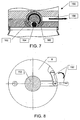
- the contents-dispensing mechanism 150 includes a rotatable dispensing element 152 that is rotatable such that a contents receptacle 160 travels between a contents inlet 154 and a contents outlet 156 (see Figure 7 ).
- the contents inlet 154 and a contents outlet 156 are spaced apart such that the as the dispensing element is rotated the contents receptacle passes through a region in which fluid communication between the contents receptacle and either the contents inlet or the contents outlet is fully interrupted before fluid communication is established with the other of either the contents inlet or contents outlet.
- the dispensing element 152 is actuated by the dispensing handle 158, which may be rotated between an open and a closed state (see Figure 8 ). It is preferable that the dispensing element 152 be seated in a vacuum seal seat 162 so as to prevent a vacuum leak between the dispensing element 152 and the seat-portion 106 of the lid assembly 100.
- the dispensing element 152 may be of substantially any suitable shape, such as but not limited to, a sphere (as illustrated herein) and a cylinder.
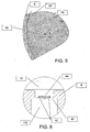
- the contents receptacle 160 may be of substantially any suitable size or shape corresponding to the contents 164 of the container, as illustrated in Figure 9 .
- the contents receptacle 160 may be configured to hold a predetermined number, for example, 1, 2 or more, of individual contents items, such as but not limited to pills and capsules. Alternately, the contents receptacle 160 may be configured to hold a predetermined amount or volume of contents, such as but not limited to, powdered, granulated, and liquid contents.
- the dispensing element 152 may be biased to a normal state in which the contents receptacle 160 is aligned with the contents inlet 154. That is, after the contents have been dispensed through the contents outlet 156, the dispensing element 152 will automatically return to a position in which the contents receptacle 160 is in fluid connection with the interior of the container 4.
- controlling access to the contents of the container may be of concern, such as keeping children from opening medication containers, for example.
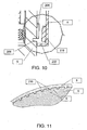
- the actuating ring 8 is configured with a selectively engagable lid-removal mechanism 200 (see Figures 2 and 10 ). In a normally relaxed state, the actuating ring 8 is biased, by either gravity or a spring configuration for example, such that an inwardly extending lip 202 rests of the outer surface of the seat-portion 6.
- the actuating ring 8 is raised, or moved longitudinally away from the container until lip 202 strikes the bottom edge of a plurality of teeth 204 that circumscribe the outer surface of the seat-portion 6, at which point the lip 202 is aligned with groove 206 which also circumscribes the seat-portion 6. At least a portion of the actuating ring 8 is then compressed inwardly such that at least a portion of lip 202 enters groove 206 and a number of complementary teeth 210, which circumscribe the inner surface of the actuating ring, engage a number of teeth 204.
- Rotation of the actuating ring 8 in relation to the seat-portion 6 is thereby locked and the lid assembly may be unscrewed by rotating the actuating ring 8, and therefore the entire lid assembly 2. Removal of the lid assembly therefore is a three-step process. First, lifting the actuating ring, then pressing a portion of the actuating ring against the set-portion, and finally turning the lid assembly.
- some embodiments of the present invention are configured with a filter 170 deployed in a passageway 172 through the seat-portion 6 connecting the interior of the container to the variable pump volume within the pump configuration.
- the filter 170 may be permanently installed during manufacture, or the filter 170 may be a replaceable filter.
- FIG. 12 illustrates a lid assembly 300 constructed and operable according to the teachings of the present invention and including a pressure differential indicator configured here as a vacuum indicator 310.
- the vacuum indicator 310 is configured as a passageway 312 through the lid assembly 300 extending between the interior 304 of the container and the exterior atmosphere.
- the passageway 312 is closed by a vacuum indicating element 314.
- the vacuum indicating element illustrated here is plug 314 configured from a resilient material that is deformable between a first formation, which indicates that the interior 304 of the container is in a non-vacuum state, and a second formation that indicates that the interior 304 of the container is in a vacuum state. In the first formation, the plug 314 is normally biased so as to be substantially planar.
- the vacuum indicating element may be configured as, by non-limiting example, a button on a stem, which seals the passageway, that is normally biased to extend above the top surface of the piston 10, and when a vacuum state is created within the interior of the container, the button is drawn downward.
- the indicator when used with embodiments configured to pressurize the interior of the container, the indicator may be configured as a pressure indicator.
- valves of the pump are configured to create a vacuum within the interior of the container or to pressurize the interior of the container
- the operation of the lid is basically the same. That is, as the actuating ring is turned, gasses are drawn into and then forced out of the pump. For creating a vacuum in the container, gasses are drawn from the interior of the container and forced out into the atmosphere. For pressurizing the container, gasses are drawn from the atmosphere and force into the interior of the container. In either case, the pump lid creates a pressure differential. That is a pressure different from atmospheric, within the interior of the container.
- the primary variation in this preferred embodiment is the integration of the substantially cylindrical pump piston 510 and the piston actuating ring 508 into a single actuating ring/piston element 502.
- the lid assembly 500 is secured on the container 504 by seat-portion 506.
- a portion of the seat-portion is configured so as to define at least part of a pump cylinder 506P. Circumscribing at least a portion of the pump cylinder 506P is the actuating ring portion 8 of the actuating ring/piston element 502.
- the variable pump volume is defined between the pump cylinder 506P and the substantially cylindrical pump piston portion 510 of the actuating ring/piston element 502 deployed therein.
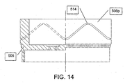
- the outer circumferential wall of the cylinder 506P is configured with the longitudinally-wave-like groove 514 as described above.
- the piston actuating ring 508 is configured with a pump activation pin 516 that extends into the groove 514.
- the pump activating pin 516 contacts the edge of the groove 514. Due to the angle of the groove 514 in relation to the direction of the movement of the pump activating pin 516, the torque of the actuating ring 508 is translated into linear motion of the actuating ring/piston element 502. As described above, the wave-like configuration of the groove 514, therefore, results in reciprocating linear motion of the actuating ring/piston element 502. It will be appreciated that a configuration in which the wave-like groove is configured in the actuating ring 508 and the pump activating pin configured in the wall of the cylinder 506P is within the spirit of the present invention.
- the pump When the pump is configured as a vacuum pump, as illustrated in Figure 13 , as the piston 510 moves in a linear direction away from the seat-portion 506, the variable pump volume increases in volume and gases are drawn from the interior of the container 504 into the pump through the one-way pump inlet valve 518. As the piston 510 moves in a linear direction toward seat-portion 506, the variable pump volume decreases in volume, pressure in the variable pump volume increases, and gases are forced from the pump to the surrounding atmosphere through the one-way valve 520. It will be appreciated that substantially any one-way valve such as but not limited to, flap valves and ball valves, may be used to control the direction of flow of gasses through the pump of the present invention.
- substantially any one-way valve such as but not limited to, flap valves and ball valves, may be used to control the direction of flow of gasses through the pump of the present invention.
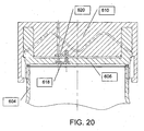
- the pump When the pump is configured as a pressurizing pump 600, as illustrated in Figure 20 , as the piston 610 moves in a linear direction away from the seat-portion 606, the variable pump volume increases in volume and gases are drawn from the surrounding atmosphere into the pump through the one-way valve 620. As the piston 610 moves in a linear direction toward the seat-portion 606, the variable pump volume decreases in volume, pressure in the variable pump volume increases, and gases are forced from the pump into the interior of the interior of the container 604 through the one-way pump valve 618.
- filter 170 be associated with pump inlet opening between the pump and the interior of the container when the pump is configured as a vacuum pump, so to a filter may be associated with the inlet opening between the pump and the atmosphere when the pump is configured to pressurized the interior of the container.
- Figure 15 shows the cap 500 associated with a contents-dispensing mechanism 150 configured in the seat-portion 506, and a filter 170, both of which are described in detail above.
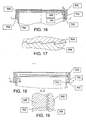
- Figures 16 and 17 illustrate an alternative ratcheting configuration that limits rotation of the actuating ring/piston element 502 to a counter-clockwise direction in relation to the seat-portion 506 of the lid assembly 500.
- FIGs 16, 18 and 19 illustrate an alternative selectively engagable lid-removal mechanism 700.
- actuating ring/piston element 502 In a normally relaxed state, actuating ring/piston element 502 is biased, by either gravity or a spring configuration for example, such that teeth 702 configured in the actuating ring portion 508 do not engage teeth 704 configured in the seat-portion 506.
- the actuating ring/piston element 502 is raised ( Figure 18 ), or moved longitudinally away from the container, until teeth 702 are aligned with teeth 704.
- teeth 702 and 704 may be configured so as to be fully engaged when the actuating ring/piston element 502 is raised.
Landscapes
- Engineering & Computer Science (AREA)
- Mechanical Engineering (AREA)
- Chemical & Material Sciences (AREA)
- Dispersion Chemistry (AREA)
- Closures For Containers (AREA)
- Sampling And Sample Adjustment (AREA)
- Compressors, Vaccum Pumps And Other Relevant Systems (AREA)
Claims (10)
- Ensemble de couvercle pour créer un différentiel de pression à l'intérieur d'un récipient, l'ensemble de couvercle comprenant :(a) une portion de siège (506) pour une connexion étanche au récipient ;(b) une configuration de pompe associée à ladite portion de siège : et(c) un élément d'actionnement rotatif (508) associé mécaniquement à ladite configuration de pompe de sorte qu'au moins une portion dudit élément d'actionnement circonscrit substantiellement au moins une portion de ladite configuration de pompe, caractérisé en ce que ledit élément d'actionnement rotatif est configuré avec un élément de pompage (510) actionné dans un mouvement linéaire alternatif pour pomper du gaz à travers ladite configuration de pompe, de sorte qu'une rotation continue dudit élément d'actionnement (508) dans une direction rotative donnée fait tourner à la fois ledit élément d'actionnement rotatif et ledit élément de pompage et génère ledit mouvement linéaire alternatif dudit élément de pompage et dudit élément d'actionnement rotatif, pompant ainsi du gaz à travers ladite configuration de pompe pour générer le différentiel de pression ;dans lequel un élément parmi ladite configuration de pompe et ledit élément d'actionnement (508) comprend une rainure (514) de type ondulé de façon longitudinal, et l'autre élément parmi ladite configuration de pompe et ledit élément d'actionnement comprend au moins une cheville d'activation de pompe (516) configurée pour mettre en prise ladite rainure de type ondulé, de sorte que pendant ladite rotation continue, ladite cheville d'activation entre en contact avec un bord de ladite rainure de type ondulé de façon longitudinale, générant ainsi ledit mouvement linéaire alternatif.
- Ensemble de couvercle selon la revendication 1, dans lequel ladite configuration de pompe comprend un cylindre de pompe (506p) configuré pour accepter ledit élément de pompage (510), une surface extérieure substantiellement cylindrique dudit cylindre de pompe est une paroi circonférentielle configurée avec ladite rainure (514) circonscrivant ladite paroi de façon à former une rainure continue unique ; et ledit élément d'actionnement (508) comprend ladite au moins une cheville d'activation de pompe (516).
- Ensemble de couvercle selon la revendication 1, comprenant en outre un mécanisme de distribution de contenu (150) pour retirer un contenu non gazeux du récipient tout en maintenant ledit différentiel de pression.
- Ensemble de couvercle selon la revendication 3, dans lequel ledit mécanisme de distribution de contenu (150) comprend un élément de distribution rotatif (152) déployé dans ladite portion de siège (106), ledit élément de distribution étant configuré avec un logement de contenu (160), et ledit élément de distribution (152) étant rotatif de telle sorte que ledit logement de contenu peut être aligné en alternance avec une entrée de contenu (154) s'ouvrant dans ledit volume intérieur et une sortie de contenu (156) s'ouvrant sur ladite atmosphère extérieure, ladite entrée de contenu et ladite sortie de contenu étant espacées de telle sorte que lorsque ledit logement de contenu (160) alterne entre ladite entrée de contenu (154) et ladite sortie de contenu (156) ledit logement de contenu passe à travers une région dans laquelle une communication fluidique entre ledit logement de contenu et l'une de ladite entrée de contenu (154) et ladite sortie de contenu (156) est complètement interrompue avant qu'une communication fluidique ne soit établie avec une autre de l'entrée de contenu et de ladite sortie de contenu.
- Ensemble de couvercle selon la revendication 1, comprenant en outre un mécanisme à cliquet pour limiter la rotation dudit élément d'actionnement dans ladite direction de rotation donnée:
- Ensemble de couvercle selon la revendication 1, comprenant en outre un indicateur de différentiel de pression (310).
- Ensemble de couvercle selon la revendication 6, dans lequel ledit indicateur de différentiel de pression (310) est configuré comme un passage (312), avec au moins une ouverture vers ledit volume intérieur du récipient et au moins une ouverture vers ladite atmosphère extérieure, ladite ouverture vers ladite atmosphère extérieure étant fermée par un élément d'indication de différentiel de pression (314) qui peut être déplacé entre deux états différents de façon à indiquer des états de différentiel de pression et de non différentiel de pression à l'intérieur du récipient.
- Ensemble de couvercle selon la revendication 7, dans lequel ledit élément d'indication de différentiel de pression est configuré à partir d'un matériau élastique (314) sollicité vers un premier état, de façon à indiquer ledit état de non différentiel de pression et déplaçable vers un deuxième étant de façon à indiquer ledit état de différentiel de pression.
- Ensemble de couvercle selon la revendication 1, dans lequel ladite configuration de pompe comprend au moins une vanne d'entrée unidirectionnelle (518) et au moins une vanne de sortie unidirectionnelle.
- Ensemble de couvercle selon la revendication 9, comprenant en outre un élément de filtre (170) associé à ladite au moins une vanne d'entrée unidirectionnelle (518).
Applications Claiming Priority (2)
| Application Number | Priority Date | Filing Date | Title |
|---|---|---|---|
| US10/725,007 US6973945B2 (en) | 2003-12-02 | 2003-12-02 | Vacuum bottle cap |
| PCT/IL2004/000830 WO2005054058A1 (fr) | 2003-12-02 | 2004-09-09 | Bouchon de bouteille a pompe |
Publications (3)
| Publication Number | Publication Date |
|---|---|
| EP1689645A1 EP1689645A1 (fr) | 2006-08-16 |
| EP1689645A4 EP1689645A4 (fr) | 2008-06-18 |
| EP1689645B1 true EP1689645B1 (fr) | 2009-06-24 |
Family
ID=34620197
Family Applications (1)
| Application Number | Title | Priority Date | Filing Date |
|---|---|---|---|
| EP04770501A Expired - Lifetime EP1689645B1 (fr) | 2003-12-02 | 2004-09-09 | Bouchon de bouteille a pompe |
Country Status (9)
| Country | Link |
|---|---|
| US (3) | US6973945B2 (fr) |
| EP (1) | EP1689645B1 (fr) |
| JP (1) | JP4787168B2 (fr) |
| AT (1) | ATE434566T1 (fr) |
| AU (1) | AU2004295201B2 (fr) |
| CA (1) | CA2547883A1 (fr) |
| DE (1) | DE602004021715D1 (fr) |
| ES (1) | ES2328246T3 (fr) |
| WO (1) | WO2005054058A1 (fr) |
Families Citing this family (34)
| Publication number | Priority date | Publication date | Assignee | Title |
|---|---|---|---|---|
| US20080131567A1 (en) * | 2003-10-01 | 2008-06-05 | Lemme Anthony R | Vacuum sealable coffee and marinating food storage container |
| US6973945B2 (en) * | 2003-12-02 | 2005-12-13 | Shlomo Haimi | Vacuum bottle cap |
| US20090250462A1 (en) * | 2004-06-14 | 2009-10-08 | Shlomo Haimi | Childproof container lid |
| US20070199612A1 (en) * | 2006-02-28 | 2007-08-30 | Bob Larimer | Decanter stopper with a vacuum pressure indicator |
| US7757725B2 (en) * | 2006-09-28 | 2010-07-20 | Kuo-Liang Wang | Manual vacuum device |
| US9517865B2 (en) | 2007-10-09 | 2016-12-13 | Oliver Albers | Airtight canister lid with flexible seal-breaking bulb |
| ITFI20080121A1 (it) * | 2008-06-30 | 2010-01-01 | Saeco Ipr Ltd | "dispositivo di separazione tra ambienti diversi e di dosaggio di un prodotto alimentare e macchina incorporante detto dispositivo" |
| US8177094B2 (en) * | 2008-12-23 | 2012-05-15 | Captech Ltd. | Pump lid and containers employing such |
| US8490795B2 (en) | 2010-02-01 | 2013-07-23 | Mallinckrodt Llc | Container and method for facilitating disposal of unused pharmaceutical product |
| US9046403B2 (en) * | 2010-02-01 | 2015-06-02 | Mallinckrodt Llc | Systems and methods for managing use of a medicament |
| US8967413B2 (en) | 2011-09-20 | 2015-03-03 | Scac Llc | Vacuum lid for use with baby food jars |
| GB2531176B (en) | 2013-03-15 | 2017-10-18 | Bissell Homecare Inc | Fluid delivery system |
| US20150307217A1 (en) * | 2014-04-23 | 2015-10-29 | Fresh Box LLC | Food preservation system |
| US10829290B2 (en) | 2016-07-27 | 2020-11-10 | Hbl Holdings, Llc | Vacuum sealable container with internal pump mechanism |
| TWM542630U (zh) * | 2017-03-10 | 2017-06-01 | Shin Hung Yih Technology Co Ltd | 便利製造容器負壓以及長時間密封的容器蓋 |
| US10896750B2 (en) * | 2018-04-24 | 2021-01-19 | Arrix, Inc. | Systems and methods for medication management |
| US11335448B2 (en) | 2018-04-24 | 2022-05-17 | Arrix, Inc. | Systems and methods for medication management |
| IT201900019088A1 (it) * | 2019-10-16 | 2021-04-16 | La Marzocco Srl | Tramoggia per macchina macina caffè dotata di dispositivo di chiusura inferiore salva chicchi e macchina macina caffè dotata di tale tramoggia |
| US11647860B1 (en) | 2022-05-13 | 2023-05-16 | Sharkninja Operating Llc | Flavored beverage carbonation system |
| US11751585B1 (en) | 2022-05-13 | 2023-09-12 | Sharkninja Operating Llc | Flavored beverage carbonation system |
| US12096880B2 (en) | 2022-05-13 | 2024-09-24 | Sharkninja Operating Llc | Flavorant for beverage carbonation system |
| US12213617B2 (en) | 2022-05-13 | 2025-02-04 | Sharkninja Operating Llc | Flavored beverage carbonation process |
| US12539500B2 (en) | 2022-08-31 | 2026-02-03 | Sharkninja Operating Llc | Additive containers |
| US12103840B2 (en) | 2022-11-17 | 2024-10-01 | Sharkninja Operating Llc | Ingredient container with sealing valve |
| US11634314B1 (en) | 2022-11-17 | 2023-04-25 | Sharkninja Operating Llc | Dosing accuracy |
| US11738988B1 (en) | 2022-11-17 | 2023-08-29 | Sharkninja Operating Llc | Ingredient container valve control |
| US11745996B1 (en) | 2022-11-17 | 2023-09-05 | Sharkninja Operating Llc | Ingredient containers for use with beverage dispensers |
| US12084334B2 (en) | 2022-11-17 | 2024-09-10 | Sharkninja Operating Llc | Ingredient container |
| USD1091308S1 (en) | 2022-12-23 | 2025-09-02 | Sharkninja Operating Llc | Ingredient container |
| USD1092208S1 (en) | 2022-12-23 | 2025-09-09 | Sharkninja Operating Llc | Cap of ingredient container |
| US11871867B1 (en) | 2023-03-22 | 2024-01-16 | Sharkninja Operating Llc | Additive container with bottom cover |
| US12116257B1 (en) | 2023-03-22 | 2024-10-15 | Sharkninja Operating Llc | Adapter for beverage dispenser |
| US11925287B1 (en) | 2023-03-22 | 2024-03-12 | Sharkninja Operating Llc | Additive container with inlet tube |
| CN116461843B (zh) * | 2023-06-19 | 2023-09-15 | 辽宁大学 | 具有防潮结构的草药用贮存容器 |
Family Cites Families (11)
| Publication number | Priority date | Publication date | Assignee | Title |
|---|---|---|---|---|
| US853658A (en) * | 1906-07-21 | 1907-05-14 | Edward Meany | Powder-dispensing receptacle. |
| US2104332A (en) * | 1935-01-23 | 1938-01-04 | Rose C Rohde | Rotatable dispensing and measuring device |
| CH537318A (de) * | 1971-03-19 | 1973-07-13 | Schneider Urs | Sicherheitsverschluss an einem Behälter |
| US5779082A (en) * | 1993-04-19 | 1998-07-14 | Invental Laboratory, Inc. | Easily-cleaned reusable lid including an evacuating pump |
| US5558243A (en) * | 1994-11-07 | 1996-09-24 | Chiun Pao Enterprise Co., Ltd. | Sealing cap for vacuum containers |
| US5961000A (en) * | 1996-11-14 | 1999-10-05 | Sanfilippo; James J. | System and method for filling and sealing containers in controlled environments |
| TW329786U (en) * | 1997-05-16 | 1998-04-11 | jin-de Zhang | Rotary vacuum can |
| US6131753A (en) * | 1999-05-17 | 2000-10-17 | Lynch; John Berrien | Vacuum jar apparatus |
| JP3670172B2 (ja) * | 1999-08-31 | 2005-07-13 | 株式会社吉野工業所 | 安全キャップ付き容器 |
| JP2003104408A (ja) * | 2001-09-26 | 2003-04-09 | Shirouma Science Co Ltd | チャイルドプルーフキャップ |
| US6973945B2 (en) * | 2003-12-02 | 2005-12-13 | Shlomo Haimi | Vacuum bottle cap |
-
2003
- 2003-12-02 US US10/725,007 patent/US6973945B2/en not_active Expired - Lifetime
-
2004
- 2004-09-09 CA CA002547883A patent/CA2547883A1/fr not_active Abandoned
- 2004-09-09 DE DE602004021715T patent/DE602004021715D1/de not_active Expired - Lifetime
- 2004-09-09 US US10/581,053 patent/US7726354B2/en not_active Expired - Fee Related
- 2004-09-09 AT AT04770501T patent/ATE434566T1/de not_active IP Right Cessation
- 2004-09-09 WO PCT/IL2004/000830 patent/WO2005054058A1/fr not_active Ceased
- 2004-09-09 ES ES04770501T patent/ES2328246T3/es not_active Expired - Lifetime
- 2004-09-09 EP EP04770501A patent/EP1689645B1/fr not_active Expired - Lifetime
- 2004-09-09 JP JP2006542109A patent/JP4787168B2/ja not_active Expired - Fee Related
- 2004-09-09 AU AU2004295201A patent/AU2004295201B2/en not_active Ceased
-
2005
- 2005-09-28 US US11/236,598 patent/US7686042B2/en not_active Expired - Fee Related
Also Published As
| Publication number | Publication date |
|---|---|
| US6973945B2 (en) | 2005-12-13 |
| AU2004295201A1 (en) | 2005-06-16 |
| US20070089802A1 (en) | 2007-04-26 |
| AU2004295201B2 (en) | 2010-04-29 |
| DE602004021715D1 (de) | 2009-08-06 |
| CA2547883A1 (fr) | 2005-06-16 |
| ES2328246T3 (es) | 2009-11-11 |
| US20050115632A1 (en) | 2005-06-02 |
| WO2005054058A1 (fr) | 2005-06-16 |
| EP1689645A1 (fr) | 2006-08-16 |
| EP1689645A4 (fr) | 2008-06-18 |
| JP2007530369A (ja) | 2007-11-01 |
| US7686042B2 (en) | 2010-03-30 |
| JP4787168B2 (ja) | 2011-10-05 |
| US20060037663A1 (en) | 2006-02-23 |
| US7726354B2 (en) | 2010-06-01 |
| ATE434566T1 (de) | 2009-07-15 |
Similar Documents
| Publication | Publication Date | Title |
|---|---|---|
| EP1689645B1 (fr) | Bouchon de bouteille a pompe | |
| KR101267966B1 (ko) | 출몰식 작동버튼을 가지는 에어리스 펌프 화장품용기 | |
| CN100402386C (zh) | 可直接连接软管的容器盖 | |
| US4105145A (en) | Mechanically operated dispensing device | |
| US5072756A (en) | Valve assembly for fluid line connection | |
| US4573611A (en) | Non-refillable valve | |
| CN1167215A (zh) | 泵塞上锁喷洒装置 | |
| JPH01124561A (ja) | 計量機能を備えた容器閉鎖キャップ | |
| US4823968A (en) | Closure for carbonated beverage container with integral pump mechanism | |
| JP6514297B2 (ja) | カプセル型内容物の排出速度が向上した包装容器 | |
| US10723537B2 (en) | Cartridge pump | |
| EP3638426A1 (fr) | Pompe à main avec buse pliante | |
| US20200307864A1 (en) | Cosmetic container | |
| US5036876A (en) | Non-refillable cylinder valve for returnable cylinders | |
| WO2012068398A2 (fr) | Récipient à deux compartiments | |
| CN1575208A (zh) | 分配泵中的防漏挡板 | |
| JP6647178B2 (ja) | ねじユニット及びねじ容器 | |
| AU770416B2 (en) | Replacement cap with pressurizing mechanism for bottle | |
| KR100920184B1 (ko) | 용기 밀폐용 진공펌프 | |
| CN217674311U (zh) | 一种旋转出液真空瓶 | |
| CN106232496B (zh) | 流体产品分配器 | |
| JP2021008289A (ja) | 吐出容器 | |
| CN210047828U (zh) | 一种长效真空保鲜盖 | |
| JP2579995Y2 (ja) | チューブ容器 | |
| KR100404459B1 (ko) | 내용물 보존성이 양호한 용기 |
Legal Events
| Date | Code | Title | Description |
|---|---|---|---|
| PUAI | Public reference made under article 153(3) epc to a published international application that has entered the european phase |
Free format text: ORIGINAL CODE: 0009012 |
|
| 17P | Request for examination filed |
Effective date: 20060531 |
|
| AK | Designated contracting states |
Kind code of ref document: A1 Designated state(s): AT BE BG CH CY CZ DE DK EE ES FI FR GB GR HU IE IT LI LU MC NL PL PT RO SE SI SK TR |
|
| AX | Request for extension of the european patent |
Extension state: AL HR LT LV MK |
|
| A4 | Supplementary search report drawn up and despatched |
Effective date: 20080519 |
|
| RIC1 | Information provided on ipc code assigned before grant |
Ipc: B65D 81/20 20060101ALI20080513BHEP Ipc: B65B 31/04 20060101AFI20050621BHEP |
|
| GRAP | Despatch of communication of intention to grant a patent |
Free format text: ORIGINAL CODE: EPIDOSNIGR1 |
|
| GRAS | Grant fee paid |
Free format text: ORIGINAL CODE: EPIDOSNIGR3 |
|
| GRAA | (expected) grant |
Free format text: ORIGINAL CODE: 0009210 |
|
| AK | Designated contracting states |
Kind code of ref document: B1 Designated state(s): AT BE BG CH CY CZ DE DK EE ES FI FR GB GR HU IE IT LI LU MC NL PL PT RO SE SI SK TR |
|
| AX | Request for extension of the european patent |
Extension state: AL HR LT LV MK |
|
| REG | Reference to a national code |
Ref country code: GB Ref legal event code: FG4D |
|
| REG | Reference to a national code |
Ref country code: CH Ref legal event code: EP |
|
| REG | Reference to a national code |
Ref country code: IE Ref legal event code: FG4D |
|
| REF | Corresponds to: |
Ref document number: 602004021715 Country of ref document: DE Date of ref document: 20090806 Kind code of ref document: P |
|
| PG25 | Lapsed in a contracting state [announced via postgrant information from national office to epo] |
Ref country code: FI Free format text: LAPSE BECAUSE OF FAILURE TO SUBMIT A TRANSLATION OF THE DESCRIPTION OR TO PAY THE FEE WITHIN THE PRESCRIBED TIME-LIMIT Effective date: 20090624 Ref country code: AT Free format text: LAPSE BECAUSE OF FAILURE TO SUBMIT A TRANSLATION OF THE DESCRIPTION OR TO PAY THE FEE WITHIN THE PRESCRIBED TIME-LIMIT Effective date: 20090624 |
|
| REG | Reference to a national code |
Ref country code: ES Ref legal event code: FG2A Ref document number: 2328246 Country of ref document: ES Kind code of ref document: T3 |
|
| LTIE | Lt: invalidation of european patent or patent extension |
Effective date: 20090624 |
|
| PG25 | Lapsed in a contracting state [announced via postgrant information from national office to epo] |
Ref country code: SI Free format text: LAPSE BECAUSE OF FAILURE TO SUBMIT A TRANSLATION OF THE DESCRIPTION OR TO PAY THE FEE WITHIN THE PRESCRIBED TIME-LIMIT Effective date: 20090624 Ref country code: SE Free format text: LAPSE BECAUSE OF FAILURE TO SUBMIT A TRANSLATION OF THE DESCRIPTION OR TO PAY THE FEE WITHIN THE PRESCRIBED TIME-LIMIT Effective date: 20090924 Ref country code: PL Free format text: LAPSE BECAUSE OF FAILURE TO SUBMIT A TRANSLATION OF THE DESCRIPTION OR TO PAY THE FEE WITHIN THE PRESCRIBED TIME-LIMIT Effective date: 20090624 |
|
| NLV1 | Nl: lapsed or annulled due to failure to fulfill the requirements of art. 29p and 29m of the patents act | ||
| PG25 | Lapsed in a contracting state [announced via postgrant information from national office to epo] |
Ref country code: EE Free format text: LAPSE BECAUSE OF FAILURE TO SUBMIT A TRANSLATION OF THE DESCRIPTION OR TO PAY THE FEE WITHIN THE PRESCRIBED TIME-LIMIT Effective date: 20090624 Ref country code: CZ Free format text: LAPSE BECAUSE OF FAILURE TO SUBMIT A TRANSLATION OF THE DESCRIPTION OR TO PAY THE FEE WITHIN THE PRESCRIBED TIME-LIMIT Effective date: 20090624 |
|
| PG25 | Lapsed in a contracting state [announced via postgrant information from national office to epo] |
Ref country code: SK Free format text: LAPSE BECAUSE OF FAILURE TO SUBMIT A TRANSLATION OF THE DESCRIPTION OR TO PAY THE FEE WITHIN THE PRESCRIBED TIME-LIMIT Effective date: 20090624 Ref country code: BE Free format text: LAPSE BECAUSE OF FAILURE TO SUBMIT A TRANSLATION OF THE DESCRIPTION OR TO PAY THE FEE WITHIN THE PRESCRIBED TIME-LIMIT Effective date: 20090624 Ref country code: NL Free format text: LAPSE BECAUSE OF FAILURE TO SUBMIT A TRANSLATION OF THE DESCRIPTION OR TO PAY THE FEE WITHIN THE PRESCRIBED TIME-LIMIT Effective date: 20090624 |
|
| PG25 | Lapsed in a contracting state [announced via postgrant information from national office to epo] |
Ref country code: BG Free format text: LAPSE BECAUSE OF FAILURE TO SUBMIT A TRANSLATION OF THE DESCRIPTION OR TO PAY THE FEE WITHIN THE PRESCRIBED TIME-LIMIT Effective date: 20090924 Ref country code: PT Free format text: LAPSE BECAUSE OF FAILURE TO SUBMIT A TRANSLATION OF THE DESCRIPTION OR TO PAY THE FEE WITHIN THE PRESCRIBED TIME-LIMIT Effective date: 20091024 |
|
| PG25 | Lapsed in a contracting state [announced via postgrant information from national office to epo] |
Ref country code: MC Free format text: LAPSE BECAUSE OF NON-PAYMENT OF DUE FEES Effective date: 20090930 Ref country code: DK Free format text: LAPSE BECAUSE OF FAILURE TO SUBMIT A TRANSLATION OF THE DESCRIPTION OR TO PAY THE FEE WITHIN THE PRESCRIBED TIME-LIMIT Effective date: 20090624 |
|
| PLBE | No opposition filed within time limit |
Free format text: ORIGINAL CODE: 0009261 |
|
| STAA | Information on the status of an ep patent application or granted ep patent |
Free format text: STATUS: NO OPPOSITION FILED WITHIN TIME LIMIT |
|
| 26N | No opposition filed |
Effective date: 20100325 |
|
| PG25 | Lapsed in a contracting state [announced via postgrant information from national office to epo] |
Ref country code: GR Free format text: LAPSE BECAUSE OF FAILURE TO SUBMIT A TRANSLATION OF THE DESCRIPTION OR TO PAY THE FEE WITHIN THE PRESCRIBED TIME-LIMIT Effective date: 20090925 |
|
| REG | Reference to a national code |
Ref country code: CH Ref legal event code: PUE Owner name: CAPTECH LTD. Free format text: HAIMI, SHLOMO#BALFOUR 641/10#30600 OR AKIVA (IL) -TRANSFER TO- CAPTECH LTD.#P.O. BOX 5057#OR AKIVA 30600 (IL) |
|
| PG25 | Lapsed in a contracting state [announced via postgrant information from national office to epo] |
Ref country code: RO Free format text: LAPSE BECAUSE OF FAILURE TO SUBMIT A TRANSLATION OF THE DESCRIPTION OR TO PAY THE FEE WITHIN THE PRESCRIBED TIME-LIMIT Effective date: 20090624 |
|
| REG | Reference to a national code |
Ref country code: GB Ref legal event code: 732E Free format text: REGISTERED BETWEEN 20110331 AND 20110406 |
|
| PG25 | Lapsed in a contracting state [announced via postgrant information from national office to epo] |
Ref country code: LU Free format text: LAPSE BECAUSE OF NON-PAYMENT OF DUE FEES Effective date: 20090909 |
|
| REG | Reference to a national code |
Ref country code: FR Ref legal event code: TP |
|
| REG | Reference to a national code |
Ref country code: ES Ref legal event code: PC2A Owner name: CAPTECH LTD. Effective date: 20110518 |
|
| PG25 | Lapsed in a contracting state [announced via postgrant information from national office to epo] |
Ref country code: HU Free format text: LAPSE BECAUSE OF FAILURE TO SUBMIT A TRANSLATION OF THE DESCRIPTION OR TO PAY THE FEE WITHIN THE PRESCRIBED TIME-LIMIT Effective date: 20091225 |
|
| PG25 | Lapsed in a contracting state [announced via postgrant information from national office to epo] |
Ref country code: TR Free format text: LAPSE BECAUSE OF FAILURE TO SUBMIT A TRANSLATION OF THE DESCRIPTION OR TO PAY THE FEE WITHIN THE PRESCRIBED TIME-LIMIT Effective date: 20090624 |
|
| REG | Reference to a national code |
Ref country code: DE Ref legal event code: R081 Ref document number: 602004021715 Country of ref document: DE Owner name: CAPTECH, LTD., IL Free format text: FORMER OWNER: HAIMI, SHLOMO, OR AKIVA, IL Effective date: 20110722 |
|
| PG25 | Lapsed in a contracting state [announced via postgrant information from national office to epo] |
Ref country code: CY Free format text: LAPSE BECAUSE OF FAILURE TO SUBMIT A TRANSLATION OF THE DESCRIPTION OR TO PAY THE FEE WITHIN THE PRESCRIBED TIME-LIMIT Effective date: 20090624 |
|
| PGFP | Annual fee paid to national office [announced via postgrant information from national office to epo] |
Ref country code: DE Payment date: 20130920 Year of fee payment: 10 Ref country code: IE Payment date: 20130918 Year of fee payment: 10 Ref country code: ES Payment date: 20130919 Year of fee payment: 10 Ref country code: CH Payment date: 20130916 Year of fee payment: 10 |
|
| PGFP | Annual fee paid to national office [announced via postgrant information from national office to epo] |
Ref country code: GB Payment date: 20130925 Year of fee payment: 10 |
|
| PGFP | Annual fee paid to national office [announced via postgrant information from national office to epo] |
Ref country code: FR Payment date: 20130930 Year of fee payment: 10 |
|
| PGFP | Annual fee paid to national office [announced via postgrant information from national office to epo] |
Ref country code: IT Payment date: 20130927 Year of fee payment: 10 |
|
| REG | Reference to a national code |
Ref country code: DE Ref legal event code: R119 Ref document number: 602004021715 Country of ref document: DE |
|
| REG | Reference to a national code |
Ref country code: CH Ref legal event code: PL |
|
| GBPC | Gb: european patent ceased through non-payment of renewal fee |
Effective date: 20140909 |
|
| REG | Reference to a national code |
Ref country code: IE Ref legal event code: MM4A |
|
| REG | Reference to a national code |
Ref country code: DE Ref legal event code: R119 Ref document number: 602004021715 Country of ref document: DE Effective date: 20150401 |
|
| REG | Reference to a national code |
Ref country code: FR Ref legal event code: ST Effective date: 20150529 |
|
| PG25 | Lapsed in a contracting state [announced via postgrant information from national office to epo] |
Ref country code: CH Free format text: LAPSE BECAUSE OF NON-PAYMENT OF DUE FEES Effective date: 20140930 Ref country code: LI Free format text: LAPSE BECAUSE OF NON-PAYMENT OF DUE FEES Effective date: 20140930 Ref country code: DE Free format text: LAPSE BECAUSE OF NON-PAYMENT OF DUE FEES Effective date: 20150401 Ref country code: GB Free format text: LAPSE BECAUSE OF NON-PAYMENT OF DUE FEES Effective date: 20140909 |
|
| PG25 | Lapsed in a contracting state [announced via postgrant information from national office to epo] |
Ref country code: IE Free format text: LAPSE BECAUSE OF NON-PAYMENT OF DUE FEES Effective date: 20140909 Ref country code: FR Free format text: LAPSE BECAUSE OF NON-PAYMENT OF DUE FEES Effective date: 20140930 Ref country code: IT Free format text: LAPSE BECAUSE OF NON-PAYMENT OF DUE FEES Effective date: 20140909 |
|
| REG | Reference to a national code |
Ref country code: ES Ref legal event code: FD2A Effective date: 20151026 |
|
| PG25 | Lapsed in a contracting state [announced via postgrant information from national office to epo] |
Ref country code: ES Free format text: LAPSE BECAUSE OF NON-PAYMENT OF DUE FEES Effective date: 20140910 |