EP1690444B1 - Tondeuse à gazon - Google Patents
Tondeuse à gazon Download PDFInfo
- Publication number
- EP1690444B1 EP1690444B1 EP05257156A EP05257156A EP1690444B1 EP 1690444 B1 EP1690444 B1 EP 1690444B1 EP 05257156 A EP05257156 A EP 05257156A EP 05257156 A EP05257156 A EP 05257156A EP 1690444 B1 EP1690444 B1 EP 1690444B1
- Authority
- EP
- European Patent Office
- Prior art keywords
- lawnmower
- grass
- box
- handle
- handle means
- Prior art date
- Legal status (The legal status is an assumption and is not a legal conclusion. Google has not performed a legal analysis and makes no representation as to the accuracy of the status listed.)
- Expired - Lifetime
Links
Images




Classifications
-
- A—HUMAN NECESSITIES
- A01—AGRICULTURE; FORESTRY; ANIMAL HUSBANDRY; HUNTING; TRAPPING; FISHING
- A01D—HARVESTING; MOWING
- A01D43/00—Mowers combined with apparatus performing additional operations while mowing
- A01D43/06—Mowers combined with apparatus performing additional operations while mowing with means for collecting, gathering or loading mown material
- A01D43/063—Mowers combined with apparatus performing additional operations while mowing with means for collecting, gathering or loading mown material in or into a container carried by the mower; Containers therefor
Definitions
- the invention relates to a lawnmower.
- a known lawnmower comprises a handle connected to a shell (or deck) in which a rotatable cutting blade is arranged, the cutting blade being rotatable about an upright axis, and being driven by a motor on top of the deck.
- the lawnmower has ground-engaging wheels at each end of the deck.
- the handle is U-shaped and each of its ends is attached to the deck.
- the handle includes a respective joint part-way along each limb, so that the distal part of the handle can be folded towards the deck to make the lawnmower more compact for storage or transport.
- Another known lawnmower is of similar construction, but does not have wheels. Instead, an impeller is arranged within the deck to cause the lawnmower to hover above the ground.
- a further known lawnmower utilises a horizontally-mounted cutting cylinder that has a plurality of blades on its periphery. Rotation of the cylinder brings the blades into close contact with a fixed bottom blade resulting in a shearing effect that is used to cut grass.
- This type of machine is usually supported on wheels or rollers.
- Each of these known types of lawnmower may be stored in its normal orientation on the floor of, for example a shed or garage, or it may be hung up by the handle so as to save on floor space. In either case, however, storage is a problem for people having limited storage space, as is often the case in garages and sheds.
- EP-A-1 543 711 describes a lawnmower having a grass-box suitable for storage.
- the aim of the invention is to provide a lawnmower that can be stored, when not in use, in a more compact configuration.
- the present invention provides a lawnmower having a body housing a cutter for cutting grass, and a grass-box, one end of which is detachably mountable to one end of the body for collecting grass cut by the cutter, the grass-box being open at said one end, characterised in that the grass-box is shaped so as to be slidable over the other end of the body, whereby the lawnmower can be stored with said other end body portion housed within the grass-box.
- the lawnmower further comprises a handle means pivotally attached to the body and extending, when the lawnmower is in use, over the mounted grass-box, the handle means being such as to be pivotable into a position overlying and adjacent to the body.
- the handle means is such that, when pivoted to overlie the body, it does not extend substantially beyond the footprint of the body.
- the handle means is constituted by two pivotally-connected handle members.
- the arrangement is such that, when the handle means is pivoted to overlie the body, and the lawnmower is stored with said other end body portion housed within the grass-box, the handle means and said other end body portion sandwich a portion of the grass-box.
- At least one of the walls of the grass-box is vented to permit the passage of air therethrough.
- the lawnmower may further comprise respective pairs of wheels at opposite ends of the body, and wherein the grass-box is shaped to accommodate one of said pair of wheels.
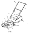
- Figure 1 shows a wheeled rotary lawnmower having a body 1 supported at the front and rear by wheels 2.
- the body 1 includes a deck 3 defining a cutting chamber (not shown) open to ground datum, the cutting chamber housing a cutting blade (not shown) which is rotatable about a substantially vertical axis.
- the cutting blade is driven by a motor (not shown) housed within a motor housing 4 forming part of the body 1.
- a U-shaped handle, indicated generally by the reference numeral 5, is pivotally attached to the rear of the body 1.
- the handle 5 is constituted by two U-shaped handle members 5a and 5b, the free ends of the limbs of the handle member 5a being pivotally attached to the rear of the body 1, and the free ends of the handle member 5b being pivotally attached to the upper end of the handle member 5a about pivot points 5c.
- Locking members (not shown) are provided for locking the two handle members 5a and 5b together in the position shown in Figure 1 .
- a grass-box 6 is detachably mounted to the rear of the body 1 of the lawnmower, the front end of the grass box being open (see Figures 3 to 5 ) for entry of cut grass from the cutting chamber via an exit aperture (not shown) provided at the rear of the cutting chamber.
- the following steps are carried out after the grass-box 6 has been emptied.
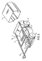
- the entire handle 5 is pivoted forwardly with respect to the body 1 of the lawnmower, as shown in Figure 2 .
- the handle 5 is then pivoted further forwards, and the grass-box 6 is removed, as shown in Figure 3 .
- the handle locking members are then removed, and the handle member 5b is be pivoted upwardly with respect to the handle member 5a, as shown in Figure 4 .
- the handle member 5b is then pivoted further, so as to lie substantially parallel to the handle member 5a, as shown in Figure 5 .
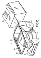
- the lawnmower can then be stored in one of two configurations, in the first of which (see Figure 6 ) the grass-box 6 is slid over the front portion of the body 1 from the front thereof, so that the top of the grass-box lies beneath the folded-over handle 5. In this position, the lawnmower can be stored, on its base and rear wheels, on the floor of a shed or a garage.
- the alternative storage configuration shown in Figure 7 , merely stands the stacked lawnmower on the base of the grass-box 6. In other respects the storage configuration being the same. In this case, the lawnmower can be stored on the floor of a shed or garage, so as to occupy a smaller area of the floor. Alternatively, the lawnmower could be hung from a hook (or other support means) fixed to a wall of a shed or a garage.
- Figure 8 shows a modified form of lawnmower constructed in accordance with the invention.
- This lawnmower is very similar to that shown in Figure 1 , and like reference numerals are used for like parts.
- the differences between the two forms of lawnmower are merely variations in the shape and configuration of the various parts thereof, the lawnmower of Figure 8 will not be described in detail.
- the various steps for re-configuring the lawnmower of Figure 8 for storage are basically the same as that for the lawnmower of Figure 1 .
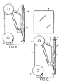
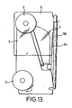
- the only difference in the storage process for the lawnmower of Figure 8 being that, after the handle 5 has been fully folded over (see Figure 11 ), the lawnmower is placed upright on a substantially horizontal surface such as the floor of a shed or garage, with the rear of the body 1 in contact with that surface. The grass-box 6 is then slid down over the front end of the body 1 of the lawnmower (see Figures 12 and 13 ). The lawnmower can then be stored in the configuration shown in Figure 13 . Alternatively, it can be stored in the position shown in Figure 14 with the lawnmower in a generally horizontal configuration.
- each of the lawnmowers described above can be stored in a more compact manner than prior art lawnmowers, owing to the complementary configurations of the grass-box 6 and the front portion of the body 1 of each of the lawnmowers. Moreover, each of the lawnmowers can be stored upright, on either its rear end or its front end in a stable position. Each can also be stored in the conventional horizontal position, but with the handle folded out of the way.
- An additional advantage of each of the lawnmowers described above is that configuring the grass-box 6 to accommodate the front of the lawnmower results in a larger grass-box, which ensures increased grass-box capacity.
- each grass-box 6 will be vented, by providing apertures in one or more of its walls, to permit air to escape. Consequently, when each of the lawnmowers is stored, its cutting chamber will not be sealed totally, thereby ensuring air circulation which prevents cut grass within the cutting chamber composting and leading to smell problems.
- the invention is applicable to any type of lawnmower.
- the invention is applicable to a non-wheeled lawnmower such as a hover mower or to a lawnmower utilising a horizontally-mounted cutting cylinder provided with blades on its periphery.
- the invention is also applicable to a lawnmower whose cutter is driven as a result of the user pushing the lawnmower rather than by a motor.
Landscapes
- Life Sciences & Earth Sciences (AREA)
- Environmental Sciences (AREA)
- Harvester Elements (AREA)
Claims (7)
- Tondeuse à gazon ayant un corps (1) recevant une lame de coupe pour couper l'herbe, et un panier à herbe (6), dont une extrémité peut être montée de manière détachable à une extrémité du corps pour recueillir l'herbe coupée par la lame de coupe, le panier à herbe étant ouvert à ladite une extrémité, caractérisée en ce que le panier à herbe est formé de manière à pouvoir coulisser par-dessus l'autre extrémité du corps, la tondeuse à gazon pouvant ainsi être rangée avec l'autre extrémité de la portion de corps logée dans le panier à herbe.
- Tondeuse à gazon selon la revendication 1, comprenant en outre un moyen de poignée (5) attaché de manière pivotante au corps (1) et s'étendant, lors de l'utilisation de la tondeuse à gazon, par-dessus le panier à herbe monté (6), le moyen de poignée étant en mesure de pivoter jusqu'à une position par-dessus le corps et adjacente à celui-ci.
- Tondeuse à gazon selon la revendication 2, dans laquelle le moyen de poignée (5) est tel que lorsqu'il est pivoté pour recouvrir le corps (1), il ne s'étend pas substantiellement au-delà du contour du corps.
- Tondeuse à gazon selon la revendication 2 ou la revendication 3, dans laquelle le moyen de poignée (5) est constitué par deux organes de poignée (5a, 5b) connectés de manière pivotante.
- Tondeuse à gazon selon l'une quelconque des revendications 2 à 4, dans laquelle l'agencement est tel que lorsque le moyen de poignée (5) est pivoté pour recouvrir le corps (1), et que la tondeuse à gazon est rangée avec ladite autre extrémité de la portion de corps logée dans le panier à herbe (6), le moyen de poignée et ladite autre extrémité de la portion de corps prennent en sandwich une portion du panier à herbe.
- Tondeuse à gazon selon l'une quelconque des revendications 1 à 5, dans laquelle au moins l'une des parois du panier à herbe (6) est ventilée de manière à permettre le passage d'air à travers elle.
- Tondeuse à gazon selon l'une quelconque des revendications 1 à 6, comprenant en outre des paires de roues respectives (2) à des extrémités opposées du corps (1), et dans laquelle le panier à herbe (6) est formé de manière à recevoir l'une des dites paires de roues.
Applications Claiming Priority (1)
| Application Number | Priority Date | Filing Date | Title |
|---|---|---|---|
| GB0503176A GB2423001B (en) | 2005-02-15 | 2005-02-15 | A lawnmower |
Publications (2)
| Publication Number | Publication Date |
|---|---|
| EP1690444A1 EP1690444A1 (fr) | 2006-08-16 |
| EP1690444B1 true EP1690444B1 (fr) | 2010-07-28 |
Family
ID=34385556
Family Applications (1)
| Application Number | Title | Priority Date | Filing Date |
|---|---|---|---|
| EP05257156A Expired - Lifetime EP1690444B1 (fr) | 2005-02-15 | 2005-11-21 | Tondeuse à gazon |
Country Status (3)
| Country | Link |
|---|---|
| EP (1) | EP1690444B1 (fr) |
| DE (1) | DE602005022545D1 (fr) |
| GB (1) | GB2423001B (fr) |
Cited By (1)
| Publication number | Priority date | Publication date | Assignee | Title |
|---|---|---|---|---|
| US9491907B2 (en) | 2011-02-21 | 2016-11-15 | Husqvarna Ab | Handle control arrangement of a walk-behind lawn mower |
Families Citing this family (5)
| Publication number | Priority date | Publication date | Assignee | Title |
|---|---|---|---|---|
| GB2445347A (en) * | 2007-01-08 | 2008-07-09 | Richard Andrew Rawcliffe | Lawnmower with rotatable grass box |
| DE202010010807U1 (de) * | 2010-07-29 | 2010-11-11 | Einhell Germany Ag | Grasauffangbox für einen Rasenmäher und Verpackungsanordnung |
| US9386743B2 (en) | 2013-03-15 | 2016-07-12 | Husqvarna Ab | Door lift and handle for walk behind mower |
| US10595460B1 (en) * | 2016-08-29 | 2020-03-24 | Briggs & Stratton Corporation | Power rake devices |
| EP4349154A4 (fr) * | 2021-06-29 | 2024-07-31 | Greenworks (Jiangsu) Co., Ltd. | Tondeuse à gazon |
Family Cites Families (6)
| Publication number | Priority date | Publication date | Assignee | Title |
|---|---|---|---|---|
| US4217747A (en) * | 1977-07-21 | 1980-08-19 | The Perfection Manufacturing Company | Lawn mower grass catcher assembly |
| DE2743115A1 (de) * | 1977-09-24 | 1979-04-05 | Karl Puehler Jun Kg | Grasfangbox fuer rasenmaeher |
| US4250698A (en) * | 1978-10-13 | 1981-02-17 | Eastern Molding International, Inc. | Grass catcher |
| US4265079A (en) * | 1979-02-05 | 1981-05-05 | The Perfection Manufacturing Company | Rigid grass catcher |
| US5606851A (en) * | 1993-09-22 | 1997-03-04 | Briggs & Stratton Corporation | Battery-powered lawn cutting system |
| DE20319777U1 (de) * | 2003-12-20 | 2004-03-11 | Olbertz, Dankmar | Rasenmäher |
-
2005
- 2005-02-15 GB GB0503176A patent/GB2423001B/en not_active Expired - Lifetime
- 2005-11-21 EP EP05257156A patent/EP1690444B1/fr not_active Expired - Lifetime
- 2005-11-21 DE DE602005022545T patent/DE602005022545D1/de not_active Expired - Lifetime
Cited By (1)
| Publication number | Priority date | Publication date | Assignee | Title |
|---|---|---|---|---|
| US9491907B2 (en) | 2011-02-21 | 2016-11-15 | Husqvarna Ab | Handle control arrangement of a walk-behind lawn mower |
Also Published As
| Publication number | Publication date |
|---|---|
| EP1690444A1 (fr) | 2006-08-16 |
| GB2423001A (en) | 2006-08-16 |
| GB2423001B (en) | 2008-02-13 |
| GB0503176D0 (en) | 2005-03-23 |
| DE602005022545D1 (de) | 2010-09-09 |
Similar Documents
| Publication | Publication Date | Title |
|---|---|---|
| US4015406A (en) | Lawnmower bagging apparatus | |
| US6052976A (en) | Trimmer shield for grass trimmer | |
| CN222193147U (zh) | 手扶式割草机 | |
| US6751871B2 (en) | Vegetation cutter/catcher | |
| US5983613A (en) | Vacuum mower | |
| EP1690444B1 (fr) | Tondeuse à gazon | |
| EP1776858A1 (fr) | Châssis de tondeuse convertible | |
| US9750186B2 (en) | Walk-behind mower including debris container | |
| EP1512319A2 (fr) | Tondeuse à gazon | |
| US4244164A (en) | Safety lawn mower and grass collector | |
| US6298645B1 (en) | Universal fruit-picking tool | |
| WO2018060500A1 (fr) | Appareil de fauchage | |
| US10959375B1 (en) | Refuse catcher bag for a ground tending machine | |
| WO2022198137A1 (fr) | Appareil d'ensachage pour outil d'entretien de pelouse à haut rendement | |
| EP1627560B1 (fr) | Une tondeuse à gazon | |
| US6675566B2 (en) | Tool, such as a lawnmower or the like, particularly for gardening vehicles | |
| GB2441203A (en) | Lawn mower with storage cover | |
| EP1695608B1 (fr) | Une tondeuse à gazon | |
| WO2023275518A1 (fr) | Collecteur pour tondeuse montée à mi-hauteur | |
| EP1304027B1 (fr) | Tondeuse à gazon | |
| EP1419686B1 (fr) | Tondeuse à gazon | |
| GB2445347A (en) | Lawnmower with rotatable grass box | |
| JPH06169624A (ja) | 芝刈機における可変コレクタ | |
| JPH0353629Y2 (fr) | ||
| CN215774420U (zh) | 一种古枣树修剪用修剪装置壳 |
Legal Events
| Date | Code | Title | Description |
|---|---|---|---|
| PUAI | Public reference made under article 153(3) epc to a published international application that has entered the european phase |
Free format text: ORIGINAL CODE: 0009012 |
|
| AK | Designated contracting states |
Kind code of ref document: A1 Designated state(s): AT BE BG CH CY CZ DE DK EE ES FI FR GB GR HU IE IS IT LI LT LU LV MC NL PL PT RO SE SI SK TR |
|
| AX | Request for extension of the european patent |
Extension state: AL BA HR MK YU |
|
| 17P | Request for examination filed |
Effective date: 20060825 |
|
| 17Q | First examination report despatched |
Effective date: 20060929 |
|
| AKX | Designation fees paid |
Designated state(s): DE FR GB |
|
| GRAP | Despatch of communication of intention to grant a patent |
Free format text: ORIGINAL CODE: EPIDOSNIGR1 |
|
| GRAS | Grant fee paid |
Free format text: ORIGINAL CODE: EPIDOSNIGR3 |
|
| GRAA | (expected) grant |
Free format text: ORIGINAL CODE: 0009210 |
|
| AK | Designated contracting states |
Kind code of ref document: B1 Designated state(s): DE FR GB |
|
| REG | Reference to a national code |
Ref country code: GB Ref legal event code: FG4D |
|
| REF | Corresponds to: |
Ref document number: 602005022545 Country of ref document: DE Date of ref document: 20100909 Kind code of ref document: P |
|
| PLBE | No opposition filed within time limit |
Free format text: ORIGINAL CODE: 0009261 |
|
| STAA | Information on the status of an ep patent application or granted ep patent |
Free format text: STATUS: NO OPPOSITION FILED WITHIN TIME LIMIT |
|
| 26N | No opposition filed |
Effective date: 20110429 |
|
| REG | Reference to a national code |
Ref country code: DE Ref legal event code: R097 Ref document number: 602005022545 Country of ref document: DE Effective date: 20110429 |
|
| REG | Reference to a national code |
Ref country code: GB Ref legal event code: 732E Free format text: REGISTERED BETWEEN 20140904 AND 20140910 |
|
| REG | Reference to a national code |
Ref country code: FR Ref legal event code: TP Owner name: HUSQVARNA AB, SE Effective date: 20150119 |
|
| REG | Reference to a national code |
Ref country code: DE Ref legal event code: R081 Ref document number: 602005022545 Country of ref document: DE Owner name: HUSQVARNA AB, SE Free format text: FORMER OWNER: HUSQVARNA UK LTD., NEWTON AYCLIFFE, DURHAM, GB Effective date: 20150317 |
|
| REG | Reference to a national code |
Ref country code: FR Ref legal event code: PLFP Year of fee payment: 11 |
|
| REG | Reference to a national code |
Ref country code: FR Ref legal event code: PLFP Year of fee payment: 12 |
|
| REG | Reference to a national code |
Ref country code: FR Ref legal event code: PLFP Year of fee payment: 13 |
|
| REG | Reference to a national code |
Ref country code: FR Ref legal event code: PLFP Year of fee payment: 14 |
|
| P01 | Opt-out of the competence of the unified patent court (upc) registered |
Effective date: 20230419 |
|
| PGFP | Annual fee paid to national office [announced via postgrant information from national office to epo] |
Ref country code: DE Payment date: 20241014 Year of fee payment: 20 |
|
| PGFP | Annual fee paid to national office [announced via postgrant information from national office to epo] |
Ref country code: GB Payment date: 20241007 Year of fee payment: 20 |
|
| PGFP | Annual fee paid to national office [announced via postgrant information from national office to epo] |
Ref country code: FR Payment date: 20241008 Year of fee payment: 20 |
|
| REG | Reference to a national code |
Ref country code: DE Ref legal event code: R071 Ref document number: 602005022545 Country of ref document: DE |
|
| REG | Reference to a national code |
Ref country code: GB Ref legal event code: PE20 Expiry date: 20251120 |