EP1693134B1 - Porte-taraud - Google Patents
Porte-taraud Download PDFInfo
- Publication number
- EP1693134B1 EP1693134B1 EP06003089A EP06003089A EP1693134B1 EP 1693134 B1 EP1693134 B1 EP 1693134B1 EP 06003089 A EP06003089 A EP 06003089A EP 06003089 A EP06003089 A EP 06003089A EP 1693134 B1 EP1693134 B1 EP 1693134B1
- Authority
- EP
- European Patent Office
- Prior art keywords
- sleeve
- tool
- collet chuck
- outer body
- chuck according
- Prior art date
- Legal status (The legal status is an assumption and is not a legal conclusion. Google has not performed a legal analysis and makes no representation as to the accuracy of the status listed.)
- Expired - Lifetime
Links
Images
Classifications
-
- B—PERFORMING OPERATIONS; TRANSPORTING
- B23—MACHINE TOOLS; METAL-WORKING NOT OTHERWISE PROVIDED FOR
- B23B—TURNING; BORING
- B23B31/00—Chucks; Expansion mandrels; Adaptations thereof for remote control
- B23B31/02—Chucks
- B23B31/08—Chucks holding tools yieldably
- B23B31/083—Chucks holding tools yieldably axially
-
- B—PERFORMING OPERATIONS; TRANSPORTING
- B23—MACHINE TOOLS; METAL-WORKING NOT OTHERWISE PROVIDED FOR
- B23B—TURNING; BORING
- B23B2215/00—Details of workpieces
- B23B2215/68—Threaded components
-
- B—PERFORMING OPERATIONS; TRANSPORTING
- B23—MACHINE TOOLS; METAL-WORKING NOT OTHERWISE PROVIDED FOR
- B23B—TURNING; BORING
- B23B2231/00—Details of chucks, toolholder shanks or tool shanks
- B23B2231/04—Adapters
-
- B—PERFORMING OPERATIONS; TRANSPORTING
- B23—MACHINE TOOLS; METAL-WORKING NOT OTHERWISE PROVIDED FOR
- B23B—TURNING; BORING
- B23B2231/00—Details of chucks, toolholder shanks or tool shanks
- B23B2231/24—Cooling or lubrication means
-
- Y—GENERAL TAGGING OF NEW TECHNOLOGICAL DEVELOPMENTS; GENERAL TAGGING OF CROSS-SECTIONAL TECHNOLOGIES SPANNING OVER SEVERAL SECTIONS OF THE IPC; TECHNICAL SUBJECTS COVERED BY FORMER USPC CROSS-REFERENCE ART COLLECTIONS [XRACs] AND DIGESTS
- Y10—TECHNICAL SUBJECTS COVERED BY FORMER USPC
- Y10S—TECHNICAL SUBJECTS COVERED BY FORMER USPC CROSS-REFERENCE ART COLLECTIONS [XRACs] AND DIGESTS
- Y10S279/00—Chucks or sockets
- Y10S279/904—Quick change socket
- Y10S279/905—Quick change socket with ball detent
-
- Y—GENERAL TAGGING OF NEW TECHNOLOGICAL DEVELOPMENTS; GENERAL TAGGING OF CROSS-SECTIONAL TECHNOLOGIES SPANNING OVER SEVERAL SECTIONS OF THE IPC; TECHNICAL SUBJECTS COVERED BY FORMER USPC CROSS-REFERENCE ART COLLECTIONS [XRACs] AND DIGESTS
- Y10—TECHNICAL SUBJECTS COVERED BY FORMER USPC
- Y10T—TECHNICAL SUBJECTS COVERED BY FORMER US CLASSIFICATION
- Y10T279/00—Chucks or sockets
- Y10T279/17—Socket type
- Y10T279/17017—Self-centering of floating
-
- Y—GENERAL TAGGING OF NEW TECHNOLOGICAL DEVELOPMENTS; GENERAL TAGGING OF CROSS-SECTIONAL TECHNOLOGIES SPANNING OVER SEVERAL SECTIONS OF THE IPC; TECHNICAL SUBJECTS COVERED BY FORMER USPC CROSS-REFERENCE ART COLLECTIONS [XRACs] AND DIGESTS
- Y10—TECHNICAL SUBJECTS COVERED BY FORMER USPC
- Y10T—TECHNICAL SUBJECTS COVERED BY FORMER US CLASSIFICATION
- Y10T279/00—Chucks or sockets
- Y10T279/17—Socket type
- Y10T279/17111—Fluid-conduit drill holding
-
- Y—GENERAL TAGGING OF NEW TECHNOLOGICAL DEVELOPMENTS; GENERAL TAGGING OF CROSS-SECTIONAL TECHNOLOGIES SPANNING OVER SEVERAL SECTIONS OF THE IPC; TECHNICAL SUBJECTS COVERED BY FORMER USPC CROSS-REFERENCE ART COLLECTIONS [XRACs] AND DIGESTS
- Y10—TECHNICAL SUBJECTS COVERED BY FORMER USPC
- Y10T—TECHNICAL SUBJECTS COVERED BY FORMER US CLASSIFICATION
- Y10T279/00—Chucks or sockets
- Y10T279/17—Socket type
- Y10T279/17761—Side detent
- Y10T279/17786—Spring
- Y10T279/17794—Sleeved
-
- Y—GENERAL TAGGING OF NEW TECHNOLOGICAL DEVELOPMENTS; GENERAL TAGGING OF CROSS-SECTIONAL TECHNOLOGIES SPANNING OVER SEVERAL SECTIONS OF THE IPC; TECHNICAL SUBJECTS COVERED BY FORMER USPC CROSS-REFERENCE ART COLLECTIONS [XRACs] AND DIGESTS
- Y10—TECHNICAL SUBJECTS COVERED BY FORMER USPC
- Y10T—TECHNICAL SUBJECTS COVERED BY FORMER US CLASSIFICATION
- Y10T279/00—Chucks or sockets
- Y10T279/17—Socket type
- Y10T279/17761—Side detent
- Y10T279/17811—Reciprocating sleeve
-
- Y—GENERAL TAGGING OF NEW TECHNOLOGICAL DEVELOPMENTS; GENERAL TAGGING OF CROSS-SECTIONAL TECHNOLOGIES SPANNING OVER SEVERAL SECTIONS OF THE IPC; TECHNICAL SUBJECTS COVERED BY FORMER USPC CROSS-REFERENCE ART COLLECTIONS [XRACs] AND DIGESTS
- Y10—TECHNICAL SUBJECTS COVERED BY FORMER USPC
- Y10T—TECHNICAL SUBJECTS COVERED BY FORMER US CLASSIFICATION
- Y10T279/00—Chucks or sockets
- Y10T279/34—Accessory or component
- Y10T279/3487—Tool or work stop or locator
-
- Y—GENERAL TAGGING OF NEW TECHNOLOGICAL DEVELOPMENTS; GENERAL TAGGING OF CROSS-SECTIONAL TECHNOLOGIES SPANNING OVER SEVERAL SECTIONS OF THE IPC; TECHNICAL SUBJECTS COVERED BY FORMER USPC CROSS-REFERENCE ART COLLECTIONS [XRACs] AND DIGESTS
- Y10—TECHNICAL SUBJECTS COVERED BY FORMER USPC
- Y10T—TECHNICAL SUBJECTS COVERED BY FORMER US CLASSIFICATION
- Y10T408/00—Cutting by use of rotating axially moving tool
- Y10T408/44—Cutting by use of rotating axially moving tool with means to apply transient, fluent medium to work or product
-
- Y—GENERAL TAGGING OF NEW TECHNOLOGICAL DEVELOPMENTS; GENERAL TAGGING OF CROSS-SECTIONAL TECHNOLOGIES SPANNING OVER SEVERAL SECTIONS OF THE IPC; TECHNICAL SUBJECTS COVERED BY FORMER USPC CROSS-REFERENCE ART COLLECTIONS [XRACs] AND DIGESTS
- Y10—TECHNICAL SUBJECTS COVERED BY FORMER USPC
- Y10T—TECHNICAL SUBJECTS COVERED BY FORMER US CLASSIFICATION
- Y10T408/00—Cutting by use of rotating axially moving tool
- Y10T408/68—Tool or tool-support with thrust-applying machine-engaging screw
-
- Y—GENERAL TAGGING OF NEW TECHNOLOGICAL DEVELOPMENTS; GENERAL TAGGING OF CROSS-SECTIONAL TECHNOLOGIES SPANNING OVER SEVERAL SECTIONS OF THE IPC; TECHNICAL SUBJECTS COVERED BY FORMER USPC CROSS-REFERENCE ART COLLECTIONS [XRACs] AND DIGESTS
- Y10—TECHNICAL SUBJECTS COVERED BY FORMER USPC
- Y10T—TECHNICAL SUBJECTS COVERED BY FORMER US CLASSIFICATION
- Y10T408/00—Cutting by use of rotating axially moving tool
- Y10T408/73—Tool or tool-support with torque-applying spline
Definitions
- the invention relates to a collet for holding a cutting tool, in particular a thread cutting tool, according to the preamble of claim 1.
- radial screws must be tightened when changing the tool to clamp the tool shank, which may also influence the radial position of the tool under unfavorable conditions.
- a shortening of the tool change times is also desirable with taps.
- said bore of the outer body has at least one polygonal nut surface which cooperates with at least one polygonal insertion surface of the sleeve to kinematically rotate the outer body and the sleeve and also to ensure the axial guidance of said sleeve in the interior of said body.
- the length of the polygonal surfaces or the necessary guidance must exceed the compensation path, which increases the overall length of the collet disadvantageous.
- the object of the invention is to increase the productivity of the machining centers by shortening the tool change times, without appreciably restricting their processing space or jeopardizing the machining accuracy.
- the sleeve for driving the tool has at least one polygonal inner driving surface, for example a square, in order to kinematically rotate the tool and the sleeve.
- an elastic material is provided on the sleeve in opposition to the return means, said elastic material being arranged so as to support the sleeve relative to the outer body. Occurring vibrations are damped.
- a reproducible axial position of the tool can be ensured even after the tool change as a reference surface is preferably the rear end face of the tool. If the stopper is designed as a screw, the position of the stopper can also be adjusted in a definable and sensitive manner. This is important if the length of the tap has changed as a result of a new bevel.
- a centrally lubricated tap can also be used.
- the supply of the cooling lubricant is carried out according to the invention then through the axial bore without adversely increasing the length.
- the cooling lubricant can be supplied under pressure, without causing major leakage, in that the sleeve is a shank which is arranged in the channel of the outer body, wherein between the insertion end and the channel a seal is arranged.
- the length of the collet is advantageously short, because said bore of the outer body by means of a plate (33) is closed, which has at least one polygonal nut surface which cooperates with at least one polygonal insertion of the sleeve to the outer body and the sleeve kinematically in To connect rotation and also to ensure the axial guidance of said sleeve in the interior of said body.
- the mounting of the plate facilitates when the plate is designed as a screw ring. After assembly, the ring is preferably secured by gluing against inadvertent twisting during use.
- the collet can also be easily disassembled. After loosening the screw ring, all internal parts can be easily removed from the collet.
- the gate of the tap is improved when the sleeve has a collar, one side of which is arranged a support surface of the spring and the other side forming a support surface of the elastic material. As a result, the feed force is slowly built up at the gate and mechanical vibrations are damped.
- the outer body has a bore for receiving the sleeve whose different diameters are formed from the outside to the inside smaller, most machining operations in the manufacture of the collet of a Side be executed, so that can be produced cheaper by this construction, the collet.
- the clamping body for quick clamping of the tool is particularly advantageous because the quick release sleeve has at least one radial bore in which a ball is provided, which is arranged on a conical inner peripheral surface supporting as a clamping body, wherein a spring, the quick release sleeve in the direction of the tapered Conical inner peripheral surface is provided movingly.
- the collet chuck according to the invention.
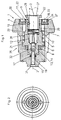
- the outer mold 25 corresponds to that of ordinary pliers which is intended to be carried by a known tong holder of a machine spindle. For example, it may be designed as a conventional Morse taper or u. a like in FIG. 3 shown.
- the collet consists essentially of three telescopically nested parts that are essentially rotationally metrical.
- the outer body 4 is externally provided with a mold 25 which is adapted to the receiving of the driving machine.
- the outer body 4 on an axial bore 5, which serves to receive an inner, the axial compensation of the movement enabling sleeve 6.
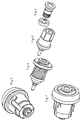
- the sleeve is three-dimensional in FIG. 5 and as an assembly in the FIG. 6 shown.
- the sleeve 6 in turn has a bore 26 into which a portion with a conical peripheral surface 24 is incorporated. Further sections of the bore 26 lead a quick-change sleeve 9, the bore 27 finally serves to receive a tool shank, not shown, whose axis is designated 2.
- the compensation enabling sleeve 6 carries outside a collar 21 which is supported on the one hand via an elastic material 8 on a shoulder of the bore 5, so that the feed force of a driving spindle on the outer body 4 and the elastic material 8 on the Bund 21 of the sleeve 6 can be transmitted.
- the collar 21 is supported by a spring 7 on a threaded ring 18, which is screwed into an internally threaded portion 27 of the bore 5.
- the spring 7 allows the guided in the threaded ring 18 and in the bore 5 sleeve 6 can move axially out of the outer body 4 against the restoring force of the spring 7 until a shoulder 20 of the sleeve 6 against the stop 19 of the screw ring 18th is moved.
- the distance of the shoulder 20 and the stopper 19 determines the axial compensation path.
- FIG. 4 shows the assembly of the quick-change sleeve with spring in perspective view.
- An axially acting compression spring 10 which is supported on one side against a shoulder 28 of the sleeve 6 and presses on the other side against the end face of the quick-change sleeve 9, exerts a restoring force on the sleeve 9 in the direction of the tapered conical surface 24 ,
- the ball 23 provided in a radial bore 29, which is supported on the conical surface 24, is pressed in the direction of the tool axis 2.
- the ball 23 serves as a clamping body 11, which spans the shaft, not shown in this drawing, of a tool arranged in the tool axis 2. On the circumference several, preferably three, such balls are distributed.
- the axial position of the tool can be adjusted by the screw 14, which serves as a stop 13.
- the screw 14 is disposed within the tool axis 2, so that when inserting the tool, the end face of the inserted tool shank can strike against the screw 14.
- the screw 14 may be fixed by means of a suitable tool, e.g. a hexagon socket to be adjusted by an axially arranged coolant hole 15.
- a suitable tool e.g. a hexagon socket to be adjusted by an axially arranged coolant hole 15.
- the sleeve 6 has an insertion end 16 with a cooling lubricant bore, which is inserted into a corresponding channel 31 of the outer body 4.
- the gap between the outer body 4 and the insertion end 16 of the sleeve 6 is closed by seal 17.
- the cooling lubricant can thus be performed in the machine axis 3 through the channel 31 and the coolant hole 15 and through a provided in the screw 14 channel 32 to the front end of a centrally lubricated, not shown tool.
- a located in the collet tool is released by pressing the collar 22 in the direction of the sleeve 6.
- the ball 23 moves radially outward on the conical peripheral surface 24 and can thus release the tool shank.
- a plurality of such balls 23 are distributed symmetrically on the circumference of the sleeve 9.
- FIGS. 3 and 7 the collet according to the invention from different directions in a three-dimensional representation and the FIGS. 4, 5 and 6 Assemblies or parts of the collet.
Landscapes
- Engineering & Computer Science (AREA)
- Mechanical Engineering (AREA)
- Gripping On Spindles (AREA)
Claims (10)
- Pince de serrage pour retenir un outil de coupe, en particulier une filière, laquelle est soumise d'une part à une rotation sur son axe et d'autre part à un mouvement axial, sachant que la pince de serrage est destinée à être portée par une fixation de pince, laquelle fixation de pince est montée sur l'axe d'une machine-outil, sachant que ladite pince de serrage présente un manchon et un corps extérieur avec un alésage, sachant que le manchon est relié cinématiquement en rotation avec le corps extérieur par des moyens, est mobile axialement à l'intérieur de l'alésage et présente des moyens pour maintenir l'outil de coupe, sachant que la forme extérieure du corps extérieur correspond à la forme de réception de la fixation de pince, sachant que des moyens qui délimitent le mouvement axial du manchon à l'intérieur de l'alésage sont prévus, ainsi que des moyens de rappel déformables élastiquement vers une position prédéterminée de repos du manchon, caractérisée en ce que les moyens pour maintenir l'outil sont un manchon à changement rapide (9) mobile axialement dans la pince de serrage respectivement dans le manchon, lequel manchon à changement rapide est formé en étant appuyé par un ressort (10) axialement par rapport au manchon (6), et qu'un corps de serrage (11, 23) pour serrer l'outil est prévu, sachant que le manchon à changement rapide (9) présente au moins un alésage radial (29) dans lequel une bille (23) est prévue qui est placée comme corps de serrage (11) en s'appuyant sur une surface périphérique intérieure conique (24), sachant qu'un ressort (10) est prévu qui déplace le manchon à changement rapide (9) en direction de la surface périphérique intérieure conique (24) qui se rétrécit, sachant que ledit alésage du corps extérieur est fermé au moyen d'une plaque (33) qui présente au moins une surface maîtresse polygonale qui interagit avec au moins une surface d'insertion polygonale du manchon pour mettre le corps extérieur et le manchon cinématiquement en rotation et garantir également le guidage axial dudit manchon à l'intérieur dudit corps.
- Pince de serrage selon la revendication 1, caractérisée en ce que le manchon (6) présente pour entraîner l'outil, au moins une surface d'entraînement (12) intérieure polygonale de préférence pour relier l'outil et le manchon (6) cinématiquement en rotation.
- Pince de serrage selon la revendication 1 ou 2, caractérisée en ce qu'un matériau élastique (8) est prévu en agissant contre les moyens de rappel (7) sur le manchon (6), lequel est placé en appuyant le manchon (6) vers le corps extérieur (4).
- Pince de serrage selon la revendication 1, 2 ou 3, caractérisée en ce qu'une butée (13) pour l'appui axial d'un outil est prévue dans le manchon (6), laquelle est une vis (14) de préférence.
- Pince de serrage selon l'une des revendications précédentes, caractérisée en ce que le corps extérieur (4) et le manchon (6) présentent au moins un canal (15) placé de préférence axialement, pour amener un lubrifiant réfrigérant.
- Pince de serrage selon la revendication 5, caractérisée en ce que le manchon (6) présente une extrémité d'insertion (16) qui est placée dans le canal (15) du corps extérieur (4), sachant qu'un joint (17) est placé entre l'extrémité d'insertion (16) et le canal (15).
- Pince de serrage selon la revendication 1, caractérisée en ce que la plaque (33) est un anneau fileté (18).
- Pince de serrage selon la revendication 1 ou 7, caractérisée en ce que le ressort (7) est placé en s'appuyant sur un anneau fileté (18) qui est prévu comme butée (19) d'un épaulement (20) d'un saut de diamètre du manchon (6).
- Pince de serrage selon l'une des revendications précédentes, caractérisée en ce que le manchon (6) présente un épaulement d'appui (21), un côté de celui-ci formant une surface d'appui du ressort (7) et l'autre côté de celui-ci formant une surface d'appui du matériau élastique (8).
- Pince de serrage selon l'une des revendications précédentes, caractérisée en ce que le corps extérieur (4) présente un alésage (5) pour recevoir le manchon (6), dont le diamètre différent se rétrécit de l'extérieur vers l'intérieur.
Applications Claiming Priority (1)
| Application Number | Priority Date | Filing Date | Title |
|---|---|---|---|
| DE102005007708A DE102005007708A1 (de) | 2005-02-18 | 2005-02-18 | Gewindebohreraufnahme |
Publications (3)
| Publication Number | Publication Date |
|---|---|
| EP1693134A2 EP1693134A2 (fr) | 2006-08-23 |
| EP1693134A3 EP1693134A3 (fr) | 2008-10-01 |
| EP1693134B1 true EP1693134B1 (fr) | 2011-04-06 |
Family
ID=36250800
Family Applications (1)
| Application Number | Title | Priority Date | Filing Date |
|---|---|---|---|
| EP06003089A Expired - Lifetime EP1693134B1 (fr) | 2005-02-18 | 2006-02-15 | Porte-taraud |
Country Status (3)
| Country | Link |
|---|---|
| US (1) | US7500811B2 (fr) |
| EP (1) | EP1693134B1 (fr) |
| DE (2) | DE102005007708A1 (fr) |
Families Citing this family (23)
| Publication number | Priority date | Publication date | Assignee | Title |
|---|---|---|---|---|
| US20070299459A1 (en) * | 2006-06-26 | 2007-12-27 | X-Sten Corp. | Percutaneous Tissue Access Device |
| FR2935917B1 (fr) * | 2008-09-12 | 2011-08-26 | E P B | Porte-outil a reglage axial |
| US8800999B2 (en) * | 2009-02-27 | 2014-08-12 | Black & Decker Inc. | Bit retention device |
| US8622401B2 (en) * | 2009-02-27 | 2014-01-07 | Black & Decker Inc. | Bit retention device |
| US8381830B2 (en) * | 2009-05-05 | 2013-02-26 | Black & Decker Inc. | Power tool with integrated bit retention device |
| CN201446519U (zh) * | 2009-06-05 | 2010-05-05 | 南京德朔实业有限公司 | 电动工具 |
| US8747033B2 (en) * | 2009-09-02 | 2014-06-10 | Lockheed Martin Corporation | Through tool coolant adapter for drilling motor |
| DE102010013430A1 (de) * | 2010-01-14 | 2011-07-21 | Bilz Werkzeugfabrik GmbH & Co. KG, 73760 | Spannfutter für Werkzeuge |
| US9027219B2 (en) | 2010-10-29 | 2015-05-12 | Gauthier Biomedical, Inc. | Shaft securing mechanism for a tool |
| US8764025B1 (en) * | 2011-09-09 | 2014-07-01 | Bradshaw Medical, Inc. | Self-locking internal adapter with free guide mechanism |
| DE102012215039A1 (de) | 2012-04-13 | 2013-10-17 | Gühring Ohg | Werkzeugaufnahme, insbesondere für ein Gewindeerzeugungswerkzeug |
| DE102012218947A1 (de) | 2012-10-17 | 2014-04-17 | Gühring KG | Spannfutter |
| US20150102567A1 (en) * | 2013-10-16 | 2015-04-16 | Fu-Yi Chan | Tool joint |
| US20150151424A1 (en) | 2013-10-29 | 2015-06-04 | Black & Decker Inc. | Power tool with ergonomic handgrip |
| USD725981S1 (en) | 2013-10-29 | 2015-04-07 | Black & Decker Inc. | Screwdriver with nosepiece |
| US10617441B2 (en) | 2016-09-07 | 2020-04-14 | Vertos Medical, Inc. | Percutaneous lateral recess resection methods and instruments |
| PL73694Y1 (pl) * | 2018-11-07 | 2024-12-02 | Promotech Spolka Z Ograniczona Odpowiedzialnoscia | Oprawka narzędziowa, zwłaszcza do wiertarek |
| CN109465505B (zh) * | 2018-12-30 | 2023-09-22 | 广西玉柴机器股份有限公司 | 一种安全防断丝锥夹头 |
| EP3875193B1 (fr) | 2020-03-05 | 2024-05-01 | Schaublin SA | Dispositif de serrage pour fixer un outil ou une pièce de travail |
| CN219027426U (zh) * | 2020-03-23 | 2023-05-16 | 米沃奇电动工具公司 | 旋转锤 |
| US12233523B2 (en) | 2020-12-07 | 2025-02-25 | Black & Decker Inc. | Power tool with multiple modes of operation and ergonomic handgrip |
| CN113909585A (zh) * | 2021-11-05 | 2022-01-11 | 上海霍冶希诺巴克运业有限公司 | ISO Tank底阀接口螺纹清理装置 |
| EP4539756A1 (fr) | 2022-06-16 | 2025-04-23 | Vertos Medical, Inc. | Ensemble d'instruments intégrés |
Family Cites Families (25)
| Publication number | Priority date | Publication date | Assignee | Title |
|---|---|---|---|---|
| US3751051A (en) * | 1971-09-14 | 1973-08-07 | Glimpel Emuge Werk | Quick-change chuck with longitudinal compensation for thread-cutting tools |
| US3967830A (en) * | 1975-11-03 | 1976-07-06 | The Theodore M. Smith Trust | Adjustable tension and/or compression tap holder |
| JPS5841974B2 (ja) * | 1978-06-08 | 1983-09-16 | マンヨ−ツ−ル株式会社 | 回転工具ホ−ルダ |
| US4752088A (en) * | 1982-03-29 | 1988-06-21 | Carboloy Inc. | Tool adapter assembly and extended compression/tension tap driver |
| US4531865A (en) * | 1982-07-21 | 1985-07-30 | Tapmatic Corporation | Tapping attachment adapted for numerical computer control |
| US4547105A (en) * | 1984-05-16 | 1985-10-15 | Reiner Bilz | Quick-change chuck |
| GB8424674D0 (en) * | 1984-09-29 | 1984-11-07 | Rotadop Halifax Ltd | Toolholders |
| US4692073A (en) * | 1985-02-25 | 1987-09-08 | Martindell J Richard | Handle adapter and chuck apparatus for power bits |
| US4810138A (en) * | 1986-09-09 | 1989-03-07 | Kuroda Seiko Company Limited | Tap holder |
| US5271697A (en) * | 1987-06-25 | 1993-12-21 | Tapmatic International Corporation (Tic Ag) | Tap and quick change tap holder assembly |
| DE3721771A1 (de) * | 1987-07-01 | 1989-01-12 | Hilti Ag | Handgeraet |
| DE3852309T2 (de) * | 1988-09-30 | 1995-06-08 | Willen Pcm Sa | Spannzange zum Halten eines Werkzeuges, insbesondere einer Schneidwerkzeuges. |
| US5464229A (en) * | 1994-05-26 | 1995-11-07 | Power Tool Holders, Inc. | Quick release chuck device |
| DE4423433C1 (de) * | 1994-07-05 | 1995-11-09 | Glimpel Emuge Werk | Schnellwechselfutter mit Längenausgleichsvorrichtung |
| US5674031A (en) * | 1994-12-21 | 1997-10-07 | Otto Bilz Werkzeugfabrik Gmbh & Co. | Tool holder in particular quick exchange chuck |
| DE19725950C2 (de) * | 1997-06-19 | 2000-04-13 | Glimpel Emuge Werk | Gewindeschneidfutter für die CNC-Maschinentechnologie "rigid tapping" |
| DE19742269C1 (de) * | 1997-09-25 | 1999-07-15 | Glimpel Emuge Werk | Schnellwechseleinsatz für Gewindebohrer |
| DE19821186C1 (de) * | 1998-05-12 | 2000-03-02 | Glimpel Emuge Werk | Gewindeschneidfutter mit Minimalmengenschmierung |
| US6126370A (en) * | 1998-07-22 | 2000-10-03 | Black & Decker Inc. | Removable tool holder |
| US6199872B1 (en) * | 1999-08-13 | 2001-03-13 | Maxtech Consumer Products, L.L.C. | Quick-release mechanism for screwdriver bits and the like |
| US6364318B1 (en) * | 1999-08-13 | 2002-04-02 | Maxtech Manufacturing Inc. | Device for holding a tool bit and selectively transmitting or releasing torque between a torque generating means and the tool bit |
| US6457916B2 (en) * | 1999-11-15 | 2002-10-01 | Insty-Bit, Inc. | Locking quick-change chuck assembly |
| IT251804Y1 (it) * | 2000-11-10 | 2004-01-20 | Meccanica Arnes Sas Di Tralli | Pinza compensata per mandrino maschiatore. |
| DE10147581C1 (de) * | 2001-09-26 | 2003-03-20 | Hermann Hauser | Spannfutter |
| US6929266B2 (en) * | 2002-06-18 | 2005-08-16 | Black & Decker Inc. | Bit holder |
-
2005
- 2005-02-18 DE DE102005007708A patent/DE102005007708A1/de not_active Withdrawn
-
2006
- 2006-02-15 EP EP06003089A patent/EP1693134B1/fr not_active Expired - Lifetime
- 2006-02-15 DE DE502006009234T patent/DE502006009234D1/de not_active Expired - Lifetime
- 2006-02-21 US US11/358,488 patent/US7500811B2/en not_active Expired - Fee Related
Also Published As
| Publication number | Publication date |
|---|---|
| EP1693134A3 (fr) | 2008-10-01 |
| DE102005007708A1 (de) | 2006-08-31 |
| EP1693134A2 (fr) | 2006-08-23 |
| DE502006009234D1 (de) | 2011-05-19 |
| US20060186614A1 (en) | 2006-08-24 |
| US7500811B2 (en) | 2009-03-10 |
Similar Documents
| Publication | Publication Date | Title |
|---|---|---|
| EP1693134B1 (fr) | Porte-taraud | |
| EP2178675B1 (fr) | Système de montage et démontage rapide | |
| DE69714781T2 (de) | Hydromechanisches futter | |
| DE3324312C2 (de) | Werkzeugmaschine mit Werkzeugwechselvorrichtung | |
| DE102010014322B4 (de) | Werkzeugkopf für ein rotierendes Werkzeug | |
| EP2014396B1 (fr) | Système de serrage d'outil assisté par force centrifuge | |
| EP1291103B1 (fr) | Mécanisme de serrage | |
| DE68902953T2 (de) | Bohrmaschine, insbesondere fuer programmierbare maschine. | |
| EP1768808B1 (fr) | Adaptateur d'outil | |
| DE3610671A1 (de) | Bohrfutter | |
| EP0972613B1 (fr) | Toc d'entraínement pour machine outil | |
| DE102017128892B4 (de) | Werkzeug-Ausrichtungsvorrichtung | |
| DE69215905T2 (de) | Spannvorrichtung für fräser oder ähnliche, anpassbar für verschiedene haltergrössen | |
| EP2314403A1 (fr) | Dispositif de tension | |
| EP1660262B1 (fr) | Point d'assemblage d'un outil | |
| DE20319597U1 (de) | Werkzeughalter-System | |
| DE1919439B2 (de) | Schnellspannfutter für einen Schaft aufweisende Werkzeuge | |
| DE3114503A1 (de) | Schnellspannfutter ii | |
| DE4025745C2 (fr) | ||
| EP0301185A1 (fr) | Dispositif de serrage pour outils d'usinage comme tarauds, fraises ou semblables, spécialement outils fabriqués entièrement en métal dur | |
| DE2454146A1 (de) | Zwischenschaft zur aufnahme von werkzeugen im spindelkopf der arbeitsspindel von werkzeugmaschinen | |
| DE3310666C2 (fr) | ||
| DE10324670B4 (de) | Spannfutter | |
| EP0172571B1 (fr) | Mandrin | |
| DE102018002429A1 (de) | Druckspannzange |
Legal Events
| Date | Code | Title | Description |
|---|---|---|---|
| PUAI | Public reference made under article 153(3) epc to a published international application that has entered the european phase |
Free format text: ORIGINAL CODE: 0009012 |
|
| AK | Designated contracting states |
Kind code of ref document: A2 Designated state(s): AT BE BG CH CY CZ DE DK EE ES FI FR GB GR HU IE IS IT LI LT LU LV MC NL PL PT RO SE SI SK TR |
|
| AX | Request for extension of the european patent |
Extension state: AL BA HR MK YU |
|
| PUAL | Search report despatched |
Free format text: ORIGINAL CODE: 0009013 |
|
| AK | Designated contracting states |
Kind code of ref document: A3 Designated state(s): AT BE BG CH CY CZ DE DK EE ES FI FR GB GR HU IE IS IT LI LT LU LV MC NL PL PT RO SE SI SK TR |
|
| AX | Request for extension of the european patent |
Extension state: AL BA HR MK YU |
|
| RIC1 | Information provided on ipc code assigned before grant |
Ipc: B23B 31/08 20060101AFI20060518BHEP Ipc: B23G 1/46 20060101ALI20080822BHEP |
|
| 17P | Request for examination filed |
Effective date: 20090401 |
|
| AKX | Designation fees paid |
Designated state(s): DE FR GB IT |
|
| 17Q | First examination report despatched |
Effective date: 20090515 |
|
| GRAP | Despatch of communication of intention to grant a patent |
Free format text: ORIGINAL CODE: EPIDOSNIGR1 |
|
| GRAS | Grant fee paid |
Free format text: ORIGINAL CODE: EPIDOSNIGR3 |
|
| GRAA | (expected) grant |
Free format text: ORIGINAL CODE: 0009210 |
|
| AK | Designated contracting states |
Kind code of ref document: B1 Designated state(s): DE FR GB IT |
|
| REG | Reference to a national code |
Ref country code: GB Ref legal event code: FG4D Free format text: NOT ENGLISH |
|
| REF | Corresponds to: |
Ref document number: 502006009234 Country of ref document: DE Date of ref document: 20110519 Kind code of ref document: P |
|
| REG | Reference to a national code |
Ref country code: DE Ref legal event code: R096 Ref document number: 502006009234 Country of ref document: DE Effective date: 20110519 |
|
| PLBE | No opposition filed within time limit |
Free format text: ORIGINAL CODE: 0009261 |
|
| STAA | Information on the status of an ep patent application or granted ep patent |
Free format text: STATUS: NO OPPOSITION FILED WITHIN TIME LIMIT |
|
| 26N | No opposition filed |
Effective date: 20120110 |
|
| PGFP | Annual fee paid to national office [announced via postgrant information from national office to epo] |
Ref country code: FR Payment date: 20120228 Year of fee payment: 7 |
|
| REG | Reference to a national code |
Ref country code: DE Ref legal event code: R097 Ref document number: 502006009234 Country of ref document: DE Effective date: 20120110 |
|
| PGFP | Annual fee paid to national office [announced via postgrant information from national office to epo] |
Ref country code: GB Payment date: 20120222 Year of fee payment: 7 Ref country code: IT Payment date: 20120223 Year of fee payment: 7 |
|
| GBPC | Gb: european patent ceased through non-payment of renewal fee |
Effective date: 20130215 |
|
| REG | Reference to a national code |
Ref country code: FR Ref legal event code: ST Effective date: 20131031 |
|
| PG25 | Lapsed in a contracting state [announced via postgrant information from national office to epo] |
Ref country code: IT Free format text: LAPSE BECAUSE OF NON-PAYMENT OF DUE FEES Effective date: 20130215 |
|
| PG25 | Lapsed in a contracting state [announced via postgrant information from national office to epo] |
Ref country code: GB Free format text: LAPSE BECAUSE OF NON-PAYMENT OF DUE FEES Effective date: 20130215 Ref country code: FR Free format text: LAPSE BECAUSE OF NON-PAYMENT OF DUE FEES Effective date: 20130228 |
|
| PGFP | Annual fee paid to national office [announced via postgrant information from national office to epo] |
Ref country code: DE Payment date: 20140422 Year of fee payment: 9 |
|
| REG | Reference to a national code |
Ref country code: DE Ref legal event code: R119 Ref document number: 502006009234 Country of ref document: DE |
|
| PG25 | Lapsed in a contracting state [announced via postgrant information from national office to epo] |
Ref country code: DE Free format text: LAPSE BECAUSE OF NON-PAYMENT OF DUE FEES Effective date: 20150901 |