EP1693199A2 - Méthode et appareil pour appliquer une correction d'impression - Google Patents
Méthode et appareil pour appliquer une correction d'impression Download PDFInfo
- Publication number
- EP1693199A2 EP1693199A2 EP05028390A EP05028390A EP1693199A2 EP 1693199 A2 EP1693199 A2 EP 1693199A2 EP 05028390 A EP05028390 A EP 05028390A EP 05028390 A EP05028390 A EP 05028390A EP 1693199 A2 EP1693199 A2 EP 1693199A2
- Authority
- EP
- European Patent Office
- Prior art keywords
- printing
- correction
- processing
- product
- Prior art date
- Legal status (The legal status is an assumption and is not a legal conclusion. Google has not performed a legal analysis and makes no representation as to the accuracy of the status listed.)
- Granted
Links
- 238000000034 method Methods 0.000 title claims abstract description 60
- 238000007639 printing Methods 0.000 claims abstract description 144
- 238000012545 processing Methods 0.000 claims abstract description 131
- 238000012937 correction Methods 0.000 claims abstract description 84
- 230000009467 reduction Effects 0.000 claims description 17
- 238000004904 shortening Methods 0.000 claims description 5
- 238000011156 evaluation Methods 0.000 claims description 2
- 230000008859 change Effects 0.000 description 10
- 230000008569 process Effects 0.000 description 10
- 238000003754 machining Methods 0.000 description 6
- 239000000463 material Substances 0.000 description 6
- 238000011217 control strategy Methods 0.000 description 3
- 238000005520 cutting process Methods 0.000 description 3
- 238000011161 development Methods 0.000 description 3
- 230000018109 developmental process Effects 0.000 description 3
- 238000010586 diagram Methods 0.000 description 3
- 238000005457 optimization Methods 0.000 description 3
- 238000004080 punching Methods 0.000 description 3
- 230000006872 improvement Effects 0.000 description 2
- 230000007774 longterm Effects 0.000 description 2
- 238000005259 measurement Methods 0.000 description 2
- 230000001105 regulatory effect Effects 0.000 description 2
- 239000000758 substrate Substances 0.000 description 2
- 230000004888 barrier function Effects 0.000 description 1
- 230000008901 benefit Effects 0.000 description 1
- 238000007796 conventional method Methods 0.000 description 1
- 230000001419 dependent effect Effects 0.000 description 1
- 238000013461 design Methods 0.000 description 1
- 230000006866 deterioration Effects 0.000 description 1
- 238000010017 direct printing Methods 0.000 description 1
- 238000011143 downstream manufacturing Methods 0.000 description 1
- 238000001035 drying Methods 0.000 description 1
- 230000000694 effects Effects 0.000 description 1
- 238000011835 investigation Methods 0.000 description 1
- 238000004519 manufacturing process Methods 0.000 description 1
- 230000007246 mechanism Effects 0.000 description 1
- 238000012986 modification Methods 0.000 description 1
- 230000004048 modification Effects 0.000 description 1
- 230000002441 reversible effect Effects 0.000 description 1
- 238000005096 rolling process Methods 0.000 description 1
- 230000001360 synchronised effect Effects 0.000 description 1
Images



Classifications
-
- B—PERFORMING OPERATIONS; TRANSPORTING
- B41—PRINTING; LINING MACHINES; TYPEWRITERS; STAMPS
- B41F—PRINTING MACHINES OR PRESSES
- B41F33/00—Indicating, counting, warning, control or safety devices
- B41F33/0081—Devices for scanning register marks
-
- B—PERFORMING OPERATIONS; TRANSPORTING
- B41—PRINTING; LINING MACHINES; TYPEWRITERS; STAMPS
- B41F—PRINTING MACHINES OR PRESSES
- B41F13/00—Common details of rotary presses or machines
- B41F13/08—Cylinders
- B41F13/10—Forme cylinders
- B41F13/12—Registering devices
Definitions
- the invention relates to a method for carrying out a pressure correction according to the claims 1 and 11 and a device for printing correction according to claim 13.
- the clamping length is the same for all clichés, so that, due to the different cliché heights, different rolling lengths for the individual clichés can result.
- variable printing lengths or sizes of the printing substrates in the course of a printing process it is also disadvantageous to obtain variable printing lengths for the individual processing tools.
- One result of these are perfectly fitting printing processes for the individual processing tools and thus unclear appearance of the overall prints.
- variable tool lengths are corrected manually.
- the effective printing lengths of the individual processing tools on the printed sheets are measured individually. From these print lengths for the individual processing tools correction values are determined, which are manually entered into a printing device. This results disadvantageously in a complicated and cumbersome handling that prolongs the machining process in an undesirable manner by its time complexity. For a plurality of printing cylinders whose printing lengths are manually corrected, a disadvantageously high additional processing effort can arise in this way.
- an automated performing a pressure correction is supported, wherein the correction comprises a correction of a print length.
- the pressure correction principles known in the art can be improvedly applied.
- set-up times for printing tools can be minimized.
- An efficiency of a printing operation may thus be favorably increased.
- a preferred embodiment of the method according to the invention provides that, in addition to the correction of the printing length, a correction of a printing position is also carried out.
- print marks on the printed product can be regulated in terms of location, which supports improved alignment of individual prints and thus further improves the quality of a printing process.
- a further preferred embodiment of the method according to the invention provides that at least one first print mark is arranged in a front in the transport direction of the printed product area and at least one second print mark in a rear direction in the transport direction of the printed product.
- a further preferred embodiment of the method according to the invention provides that only a first of a plurality of processing devices applies the two print marks during the processing operation. It can thereby be achieved that, in the machining process, machining devices adjust their pressures in terms of their position to the pressure of the first machining device. It is achieved in this way so a position correction of the pressure, with the help of long-term drifts can be permanently eliminated from the printing process. Stability of the printing process is thus advantageously increased.
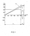
- FIG. 1 shows a diagram of a basic representation of a pressure correction according to the invention.
- a machine angle for example, a working angle of a counter-pressure cylinder
- An angle of a printing cylinder of the printing device is plotted on the y-axis.
- An area 1 on the x-axis defines a printing area and an area 2 on the x-axis defines a pressure-free zone of the printing device, i. a portion of the printing apparatus in which no printing of the printed matter is performed.
- a substantially linear course 1a represents an uncorrected course of the machine angle over the angle of the printing cylinder.
- the two angles are synchronous with each other, thereby achieving identical speeds of a printed product and a printing cylinder with a clamped printing plate.
- This can be seen in the diagram from the fact that the impression cylinder has performed a full revolution (360 °) simultaneously with the impression cylinder.
- a curve 1b represents a printing length-corrected course of the machine angle over the angle of the printing cylinder.
- the course 1b is made steeper than the course 1a, the printing cylinder thus already reaches a complete revolution earlier than the impression cylinder.
- the printing cylinder has made approximately one complete revolution (from 0 ° to 360 °) at a time when the impression cylinder has first rotated from 0 ° to 300 °. This means that the impression cylinder rotates at a higher angular velocity than the axis of the printing device that drives the impression cylinder due to the flexo flexographic printing plate.
- the printing area (area 1) of the printed product is advantageously filled by the printing length of the flexographic printing plate fully.
- a course of a correction movement of the printing cylinder is shown on the basis of a course 1c.
- the printing cylinder with the printing plate is positionally corrected so that it again assumes a defined common position together with the impression cylinder at the beginning of a next printing area at 360 ° or 0 °.
- the pressure cylinder in the pressure-free zone performs a braking movement (negative slope of the S-curve).
- This has the consequence that the speed profile of the correction movement of the printing cylinder in the short term goes into the negative range, pressure cylinder and impression cylinder thus briefly have opposite angular velocities.
- the speed profile remains completely in the positive range, which means that the angular velocity of the printing cylinder has the same sign as the angular velocity of the impression cylinder.
- APM function anti-proline analysis mode
- the individual print length-corrected courses 1b for the individual printing cylinders with the printing plates are stored as correction parameters in the printing device and are automatically converted in the print-free zone (area 2) into correction movements for the individual printing cylinders of the processing devices.
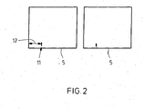
- Figure 2 shows two individual printed products 5, on each of which a single print mark is arranged at a defined distance from a sheet edge of the printed product 5.
- Conventional register controllers use these individual print marks as reference marks to align subsequent print stations to the reference marks.
- FIG. 3 shows a printing area of a printed product 5.
- a first print mark A has been applied by a first processing device and a second print mark B has been applied by the first processing device.
- a first print mark C has been applied by a second processing device and a second print mark D has been applied by the second processing device.
- printed images of the processing stations can also have been applied.
- these prints are not shown in FIG. It can be seen that the first print marks A, C of the two processing devices have different distances in relation to a front edge of the printed product 5 in the material flow direction. Furthermore, it can be seen from FIG.
- FIG. 3 shows a state of the printed product 5 before the printing correction according to the invention is carried out.
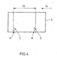
- FIG. 4 shows the printed product 5 after a correction of the printing length according to the invention has been carried out. It can be seen that the first print marks A, C of the first and second processing devices have substantially identical spacings in relation to the second print marks B, D of the two processing devices. This means that the printing lengths of the two processing devices are corrected according to the invention or that the printing length of the second processing device has been adapted to the printing length of the first processing device.
- the method according to the invention advantageously automatically performs the pressure correction in such a way that in the printing area (area 1) a relative movement is effected between the printing cylinder and the counter-pressure cylinder as a result of different tool lengths. This allows the different Print lengths of the individual pressure cylinders are compensated.
- the method according to the invention is therefore characterized in that the correction is carried out automatically.
- the pressure correction according to the invention can work much more efficiently than the conventional methods.
- the positions of the corrected print marks C, D from FIG. 4 can only be seen as examples, so that any predefinable positions of the first and second print marks C, D of the second processing device are also conceivable.
- a fixed, predeterminable position of the print marks of the first and the second processing device relative to one another is the result of the method according to the invention.
- FIG. 4 shows a control strategy which is configured in such a way that print marks A, B applied by the first processing device are used to control printing steps of subsequent processing devices.
- FIG. Figure 5 shows within the printing range of a printed product 5 two print marks A, B which have been applied by the first processing device.
- the two print marks A, B have already been printed before a processing operation in the first processing device.
- the printed product 5 is a pre-printed with two reference print marks printing material.
- the further control strategy is characterized in that the stations following the first processing device detect the position of the two print marks A, B of the first processing device and set their printing steps in relation to the print marks A, B.
- this embodiment of the invention is an actuating mechanism that uses reference printing marks A, B to align the subsequent processing devices thereto.
- An embodiment of the method according to the invention thus allows, as described above, an overall correction of a pressure in two sub-steps.
- a first sub-step while the position of the second print marks B, D is controlled to each other (printing length correction)
- a second sub-step the position of the first print marks A, C to each other regulated (printing position correction).
- the described sub-steps can also be performed in reverse order to each other.
- FIG. 7 shows a device 1 for pressure correction with which the method according to the invention can be carried out.
- the device 1 comprises a plurality of processing devices 4a, 4b, 4c in which a printed product 5 is printed by a respective printing cylinder 6. With the help of transport devices 3, the printed product 5 is transported from one processing device 4a, 4b, 4c to the next processing device 4a, 4b, 4c.
- a device 2 is used for detecting and evaluating the positions of the print marks on the printed products 5.
- the device 2 may comprise, for example, a light barrier, a camera and a computing unit, which are used to supply detected correction data to the processing devices 4a, 4b, 4c.
- Controller outputs 7 of the processing devices 4a, 4b, 4c detect a result of the pressure correction according to the invention, ie they determine whether the result of the pressure correction are print length reductions or print length extensions.
- both the processing devices 4a, 4b, 4c and the transport device 3 can be used.
- the transport of the printed product 5 by means of the transport device 3 takes place at a substantially constant speed
- the printing cylinders 6 of the processing devices 4a, 4b, 4c performing a relative movement to the printed product 5.
- the transport of the printed product 5 by means of the transport device 3 takes place at a non-constant speed. This has the consequence that the transport process of the printed product 5 is corrected, which can be carried out for example by a correction of a speed control for the transport device 3.
- the printed product 5 is fed by means of the transport device 3 to the first processing device 4a.
- the first print mark A of the first processing device 4a and the second print mark B of the first processing device 4a are applied.
- the printed product 5 is supplied by means of the transport device 3 to the second processing device 4b.
- the first print mark C of the second processing device 4b and the second print mark D of the second processing device 4b is applied to the printed product 5.
- the printed product 5 is supplied with the applied print marks A, B, C, D by means of the transport device 3 to the third processing device 4c.
- the means 2 for detecting positions of print marks of the third processing means 4c detects the positions of the print marks A, B, C, D on the printed product 5 and evaluates the positions of the print marks A, B, C, D. If the device 2 determines that the distance of the print marks A to B deviates from the distance of the print marks C to D, this means that the effective print lengths of the first processing device 4a and the second processing device 4b are different.
- the second processing device 4b is then activated via a controller output 7 of the third processing device 4c.
- the impression cylinder 6 is moved by the transport means 3 or the processing means 4b in relation to the print product 5 such that the second processing means 4b is substantially identical to the first processing means 4a Print length generated on the printed product 5.
- a parameter value for the correction movement of the second processing device 4b can be stored in the second processing device 4b, so that for all other printed products 5 during their processing by the second processing device 4b the pressure correction according to the invention is carried out automatically.
- the second processing device 4b can be controlled via the controller output 7 of the third processing device 4c such that the positions of the first print mark C are also adapted to the position of the first print mark A of the first processing device 4a.
- a pressure position correction is advantageously carried out in addition to the printing length correction.
- the described correction method is not limited to a correction of the print marks C, D of only the second processing device 4b, but may extend to a plurality of different processing devices 4a, 4b, 4c. For the sake of simplicity, however, only the correction of print marks C, D of the second processing device 4b has been described above.
- the controller outputs 7 of the processing devices 4a, 4b, 4c are checked for possible reductions in print length. If one or more printing units are present due to the printing correction according to the invention with resulting printing length reduction, the reference pressure is changed such that no printing unit due to the control / position performs a print length reduction or only a maximum predetermined print length reduction. This can be achieved, for example, by correcting the printing unit of the reference color by a suitable amount (printing length extension of the reference print).
- the numbers indicate changes in the printing lengths of the individual processing devices 4a, 4b, 4c in millimeters, the first of the five numerical values representing a printing length change for the reference pressure.
- a positive sign means a print length extension and a negative sign a print length shortening of a following processing device 4a, 4b, 4c. Therefore, before applying the improved algorithm, a maximum print length change includes a 3mm print length reduction (previously: from 0mm to -3mm). After applying the improved algorithm, the Change in print length no reduction in print length. (After: from + 3mm to +4mm).
- a modification of the algorithm can result in the reference pressure being changed in such a way that at least an absolute reduction in the maximum reduction of the printing length in the machine results.
- Printing length changes of the printing units (1st change is reference pressure) Before: 0mm, + 1mm, + 2mm, -3mm, + 1mm.
- the reference pressure is printed such that reductions in printing no longer occur for subsequent prints of subsequent processing devices 4a, 4b, 4c.
- An improvement of the printed image is thereby supported in an advantageous manner.
- the method according to the invention can advantageously be carried out with different types of processing devices 4a, 4b, 4c.
- a processing device 4a, 4b, 4c a slotter, a punch or a cross cutter can be used.
- slot machines means 4a, 4b, 4c, the longitudinal slots in insert the printed product 5.
- Punching means processing means 4a, 4b, 4c which perform all other slitting and cutting operations on the printed products 5, such as transverse slits, corrugations or breakouts.
- Cross-cutters are to be understood as processing devices 4a, 4b, 4c which intersect in the transverse direction.
Landscapes
- Engineering & Computer Science (AREA)
- Mechanical Engineering (AREA)
- Inking, Control Or Cleaning Of Printing Machines (AREA)
- Ink Jet (AREA)
- Measuring Fluid Pressure (AREA)
- Diaphragms For Electromechanical Transducers (AREA)
- Fluid-Pressure Circuits (AREA)
- Printing Methods (AREA)
Applications Claiming Priority (1)
| Application Number | Priority Date | Filing Date | Title |
|---|---|---|---|
| DE102005007435A DE102005007435A1 (de) | 2005-02-18 | 2005-02-18 | Verfahren zum Durchführen einer Druckkorrektur und Vorrichtung hierfür |
Publications (4)
| Publication Number | Publication Date |
|---|---|
| EP1693199A2 true EP1693199A2 (fr) | 2006-08-23 |
| EP1693199A3 EP1693199A3 (fr) | 2007-01-17 |
| EP1693199B1 EP1693199B1 (fr) | 2008-10-15 |
| EP1693199B2 EP1693199B2 (fr) | 2013-01-16 |
Family
ID=36297320
Family Applications (1)
| Application Number | Title | Priority Date | Filing Date |
|---|---|---|---|
| EP05028390A Expired - Lifetime EP1693199B2 (fr) | 2005-02-18 | 2005-12-23 | Méthode et appareil pour appliquer une correction d'impression |
Country Status (6)
| Country | Link |
|---|---|
| US (1) | US7337035B2 (fr) |
| EP (1) | EP1693199B2 (fr) |
| JP (1) | JP2006224673A (fr) |
| AT (1) | ATE411174T1 (fr) |
| DE (2) | DE102005007435A1 (fr) |
| ES (1) | ES2315784T5 (fr) |
Cited By (1)
| Publication number | Priority date | Publication date | Assignee | Title |
|---|---|---|---|---|
| WO2012038069A1 (fr) | 2010-09-21 | 2012-03-29 | Bobst Sa | Procede et agencement de mise en registre des couleurs pour une machine d'impression |
Families Citing this family (10)
| Publication number | Priority date | Publication date | Assignee | Title |
|---|---|---|---|---|
| US20090283002A1 (en) * | 2005-09-02 | 2009-11-19 | Stephan Schultze | Method for printing correction |
| DE102007034835A1 (de) * | 2007-07-26 | 2009-01-29 | Robert Bosch Gmbh | Verfahren zum Betreiben einer wellenlosen Druckmaschine und wellenlose Druckmaschine |
| DE102011006427A1 (de) * | 2011-03-30 | 2012-10-04 | Robert Bosch Gmbh | Drehratensensor und Verfahren zur Kalibrierung eines Drehratensensors |
| US9132623B2 (en) * | 2013-03-27 | 2015-09-15 | Unipixel Displays, Inc. | Method of marking a transparent substrate for visual alignment |
| JP6486676B2 (ja) * | 2014-12-24 | 2019-03-20 | 株式会社小森コーポレーション | 電子回路の印刷方法および装置 |
| JP6486677B2 (ja) * | 2014-12-24 | 2019-03-20 | 株式会社小森コーポレーション | 電子回路の印刷方法および装置 |
| TWI592080B (zh) * | 2014-12-24 | 2017-07-11 | Komori Corp | Electronic circuit printing method and device |
| ES2982105T3 (es) * | 2015-04-10 | 2024-10-14 | Omet Srl | Sistema de registro para unidades de impresión de una máquina de impresión rotativa con un registro de impresión de ajuste manual |
| DE102018222729A1 (de) * | 2018-12-21 | 2020-06-25 | Robert Bosch Gmbh | Bearbeitungsverfahren von Flachmaterial |
| DE102021118033A1 (de) * | 2021-07-13 | 2023-01-19 | Koenig & Bauer Ag | Bearbeitungsmaschine sowie Verfahren zur Einstellung einer Drucklänge und/oder Bearbeitungslänge |
Citations (1)
| Publication number | Priority date | Publication date | Assignee | Title |
|---|---|---|---|---|
| DE10241609A1 (de) | 2002-09-07 | 2004-03-18 | Nexpress Solutions Llc | Verfahren und Steuerungseinrichtung zum Bestimmen eines Registerfehlers |
Family Cites Families (21)
| Publication number | Priority date | Publication date | Assignee | Title |
|---|---|---|---|---|
| US3963902A (en) * | 1975-04-29 | 1976-06-15 | Westvaco Corporation | Method and apparatus for pre-registration of a multiple cylinder rotary printing press |
| NL7906131A (nl) * | 1979-08-10 | 1981-02-12 | Stork Brabant Bv | Werkwijze voor het besturen van een drukinrichting en drukinrichting met individueel bestuurbare drukorganen. |
| US4528630A (en) * | 1982-09-14 | 1985-07-09 | Oao Corporation | Automatic registration control method and apparatus |
| JPS62227747A (ja) * | 1986-03-31 | 1987-10-06 | Mitsubishi Heavy Ind Ltd | 輪転印刷機の印版周長調整装置 |
| DE3633855A1 (de) * | 1986-10-04 | 1988-04-14 | Heidelberger Druckmasch Ag | Verfahren und vorrichtung zur passerkorrektur |
| US5062360A (en) * | 1989-08-30 | 1991-11-05 | De La Rue Giori S.A. | Combined rotary web-fed printing machine, especially for the printing of securities |
| DE3933666A1 (de) * | 1989-10-09 | 1991-04-18 | Heidelberger Druckmasch Ag | Vorrichtung und verfahren zur registerverstellung an einer druckmaschine mit mehreren druckwerken |
| US5037665A (en) * | 1990-03-29 | 1991-08-06 | Enamel Products & Plating Company | Method of creating a registered pattern on a metal coil and associated apparatus |
| IT1240495B (it) * | 1990-07-20 | 1993-12-17 | Officine Meccaniche G. Cerutti S.P.A. | Meteodo per la registrazione, fra loro, di immagini monocromatiche durante la stampa di immagini policrome in una macchina da stampa rotativa. |
| DE4218760C2 (de) * | 1992-06-06 | 2000-02-03 | Heidelberger Druckmasch Ag | Anordnung von Registermarken auf einem Druckprodukt und Verfahren zur Ermittlung von Registerabweichungen |
| DE4218761C2 (de) * | 1992-06-06 | 2002-01-24 | Heidelberger Druckmasch Ag | Verfahren zum Voreinstellen von Registereinstelleinrichtungen einer Druckmaschine mit Druck von mehrfarbigen Teilbildern |
| DE59809058D1 (de) * | 1997-06-02 | 2003-08-28 | Wifag Maschf | Registerhaltige Abstimmung von Druckzylindern einer Rollenrotationsmaschine |
| FR2775930B1 (fr) * | 1998-03-11 | 2000-06-02 | Heidelberger Druckmasch Ag | Dispositif de commande de l'impression de bande de matiere dans une machine rotative a imprimer |
| CH694219A5 (fr) * | 2000-02-10 | 2004-09-30 | Bobst Sa | Procédé de mise en repérage automatique d'impressions dans une machine rotative et dispositif pour la mise en oeuvre du procédé. |
| JP3729485B2 (ja) * | 2000-07-14 | 2005-12-21 | 大日本スクリーン製造株式会社 | 製版機構を備えた印刷装置 |
| US6591746B2 (en) * | 2001-06-13 | 2003-07-15 | Hurletron, Incorporated | Registration system for printing press |
| DE10139310B4 (de) * | 2001-08-09 | 2010-11-25 | Eastman Kodak Co. | Verfahren zum Ermitteln von START OF FRAME-Korrekturdaten und START OF LINE-Korrekturdaten zur Registereinstellung für Druckmaschinen beim Mehrfarbdruck |
| DE10246072B4 (de) * | 2001-10-31 | 2009-02-12 | Heidelberger Druckmaschinen Ag | Rotationsdruckverfahren für Mehrfarbendruck |
| DE10339655A1 (de) * | 2002-09-13 | 2004-03-25 | Heidelberger Druckmaschinen Ag | Verfahren zur Kompensation von Passerdifferenzen beim Betreiben einer Druckmaschine |
| US6810813B2 (en) * | 2003-03-14 | 2004-11-02 | Heidelberger Druckmaschinen Ag | Device and method for controlling registration in a printing press |
| JP4605747B2 (ja) * | 2003-10-17 | 2011-01-05 | 株式会社ミヤコシ | バリアブル印刷機における印刷方法 |
-
2005
- 2005-02-18 DE DE102005007435A patent/DE102005007435A1/de not_active Ceased
- 2005-12-23 ES ES05028390T patent/ES2315784T5/es not_active Expired - Lifetime
- 2005-12-23 DE DE502005005683T patent/DE502005005683D1/de not_active Expired - Lifetime
- 2005-12-23 AT AT05028390T patent/ATE411174T1/de active
- 2005-12-23 EP EP05028390A patent/EP1693199B2/fr not_active Expired - Lifetime
-
2006
- 2006-02-20 JP JP2006042901A patent/JP2006224673A/ja active Pending
- 2006-02-21 US US11/359,701 patent/US7337035B2/en not_active Expired - Fee Related
Patent Citations (1)
| Publication number | Priority date | Publication date | Assignee | Title |
|---|---|---|---|---|
| DE10241609A1 (de) | 2002-09-07 | 2004-03-18 | Nexpress Solutions Llc | Verfahren und Steuerungseinrichtung zum Bestimmen eines Registerfehlers |
Cited By (2)
| Publication number | Priority date | Publication date | Assignee | Title |
|---|---|---|---|---|
| WO2012038069A1 (fr) | 2010-09-21 | 2012-03-29 | Bobst Sa | Procede et agencement de mise en registre des couleurs pour une machine d'impression |
| RU2546443C2 (ru) * | 2010-09-21 | 2015-04-10 | Бобст Мекс Са | Способ и устройство для приводки красок для печатной машины |
Also Published As
| Publication number | Publication date |
|---|---|
| US20060271230A1 (en) | 2006-11-30 |
| ATE411174T1 (de) | 2008-10-15 |
| DE502005005683D1 (de) | 2008-11-27 |
| DE102005007435A1 (de) | 2006-08-24 |
| EP1693199B2 (fr) | 2013-01-16 |
| EP1693199A3 (fr) | 2007-01-17 |
| EP1693199B1 (fr) | 2008-10-15 |
| ES2315784T5 (es) | 2013-05-14 |
| JP2006224673A (ja) | 2006-08-31 |
| US7337035B2 (en) | 2008-02-26 |
| ES2315784T3 (es) | 2009-04-01 |
Similar Documents
| Publication | Publication Date | Title |
|---|---|---|
| DE10013876B4 (de) | Verfahren zum Regeln der Farbgebung beim Drucken mit einer Druckmaschine | |
| EP2014470B1 (fr) | Procédé destiné à la régulation automatique du repérage entre les impressions dans une presse rotative multicolore | |
| DE102007049670B4 (de) | Verfahren zur Registerkorrektur bei einer Bearbeitungsmaschine sowie Bearbeitungsmaschine | |
| EP2392459B1 (fr) | Procédé et dispositif de réglage du registre d'une presse d' impression | |
| EP1820650B1 (fr) | Commande d'une presse à l'aide d'un modèle de torsion | |
| DE19516368C2 (de) | Verfahren und Vorrichtung zur Anpassung der Lage von Druckplatten an die Verformung des zu bedruckenden Papieres | |
| EP1842673A2 (fr) | Contrôle de qualité intégré | |
| EP2349721B1 (fr) | Procédé de correction automatique de l'axe sur une machine de traitement destinée à traiter un produit en bande | |
| DE102008035639A1 (de) | Verfahren zur Modellierung eines Regelkreises für eine Bearbeitungsmaschine | |
| EP1693199B1 (fr) | Méthode et appareil pour appliquer une correction d'impression | |
| EP3539777B1 (fr) | Procédé et dispositif de correction d'une position d'impression d'un groupe d'impression ainsi que imprimante | |
| WO2006114317A2 (fr) | Presse et procede pour corriger le reperage | |
| EP2879878B1 (fr) | Procédé de réglage de la longueur d'impression d'une image d'impression dans une rotative polychrome | |
| WO2007144031A1 (fr) | Dispositif et procédé de mesure et de réglage de la tension de bande entre des mécanismes d'encrage d'une machine d'impression polychrome | |
| EP1759844B1 (fr) | Procédé pour corriger l'impression | |
| DE4218761A1 (de) | Verfahren zum Voreinstellen von Registereinstellvorrichtungen an Rotationsdruckmaschinen | |
| EP1543963B1 (fr) | Procédé et dispositif pour corriger la déviation de la position d'un produit à imprimer | |
| DE102007034835A1 (de) | Verfahren zum Betreiben einer wellenlosen Druckmaschine und wellenlose Druckmaschine | |
| DE102007021787B4 (de) | Verfahren zur Steuerung einer Druckmaschine | |
| DE102011008359B3 (de) | Verfahren zur Registerregelung mit frei wählbaren Marken | |
| DE10204514B4 (de) | Vorrichtung und Verfahren zur Korrektur des Längsregisterfehlers, welcher durch die Beistellung auftritt | |
| DE102007044758B4 (de) | Verfahren zur Farbmessung und Farbregelung bei Druckmaschinen mittels internem und externem Farbmessgerät | |
| EP1645414B1 (fr) | Unité d'impression d'une machine d'impression et procédé pour changer la plaque d'un cylindre de plaque | |
| DE102015200148B4 (de) | Verfahren zur Anpassung mindestens einer Länge einer auf mehreren Druckbogen jeweils gleich groß drucktechnisch auszubildenden Fläche | |
| DE10203048C2 (de) | Verfahren und Vorrichtung zum Zuordnen von Registerabweichungen bei einer Druckmaschine |
Legal Events
| Date | Code | Title | Description |
|---|---|---|---|
| PUAI | Public reference made under article 153(3) epc to a published international application that has entered the european phase |
Free format text: ORIGINAL CODE: 0009012 |
|
| AK | Designated contracting states |
Kind code of ref document: A2 Designated state(s): AT BE BG CH CY CZ DE DK EE ES FI FR GB GR HU IE IS IT LI LT LU LV MC NL PL PT RO SE SI SK TR |
|
| AX | Request for extension of the european patent |
Extension state: AL BA HR MK YU |
|
| PUAL | Search report despatched |
Free format text: ORIGINAL CODE: 0009013 |
|
| AK | Designated contracting states |
Kind code of ref document: A3 Designated state(s): AT BE BG CH CY CZ DE DK EE ES FI FR GB GR HU IE IS IT LI LT LU LV MC NL PL PT RO SE SI SK TR |
|
| AX | Request for extension of the european patent |
Extension state: AL BA HR MK YU |
|
| 17P | Request for examination filed |
Effective date: 20070717 |
|
| 17Q | First examination report despatched |
Effective date: 20070821 |
|
| AKX | Designation fees paid |
Designated state(s): AT BE BG CH CY CZ DE DK EE ES FI FR GB GR HU IE IS IT LI LT LU LV MC NL PL PT RO SE SI SK TR |
|
| GRAP | Despatch of communication of intention to grant a patent |
Free format text: ORIGINAL CODE: EPIDOSNIGR1 |
|
| GRAS | Grant fee paid |
Free format text: ORIGINAL CODE: EPIDOSNIGR3 |
|
| GRAA | (expected) grant |
Free format text: ORIGINAL CODE: 0009210 |
|
| AK | Designated contracting states |
Kind code of ref document: B1 Designated state(s): AT BE BG CH CY CZ DE DK EE ES FI FR GB GR HU IE IS IT LI LT LU LV MC NL PL PT RO SE SI SK TR |
|
| REG | Reference to a national code |
Ref country code: GB Ref legal event code: FG4D Free format text: NOT ENGLISH Ref country code: CH Ref legal event code: EP |
|
| REG | Reference to a national code |
Ref country code: IE Ref legal event code: FG4D Free format text: LANGUAGE OF EP DOCUMENT: GERMAN |
|
| REF | Corresponds to: |
Ref document number: 502005005683 Country of ref document: DE Date of ref document: 20081127 Kind code of ref document: P |
|
| NLV1 | Nl: lapsed or annulled due to failure to fulfill the requirements of art. 29p and 29m of the patents act | ||
| REG | Reference to a national code |
Ref country code: ES Ref legal event code: FG2A Ref document number: 2315784 Country of ref document: ES Kind code of ref document: T3 |
|
| PG25 | Lapsed in a contracting state [announced via postgrant information from national office to epo] |
Ref country code: LT Free format text: LAPSE BECAUSE OF FAILURE TO SUBMIT A TRANSLATION OF THE DESCRIPTION OR TO PAY THE FEE WITHIN THE PRESCRIBED TIME-LIMIT Effective date: 20081015 Ref country code: BG Free format text: LAPSE BECAUSE OF FAILURE TO SUBMIT A TRANSLATION OF THE DESCRIPTION OR TO PAY THE FEE WITHIN THE PRESCRIBED TIME-LIMIT Effective date: 20090115 |
|
| PG25 | Lapsed in a contracting state [announced via postgrant information from national office to epo] |
Ref country code: FI Free format text: LAPSE BECAUSE OF FAILURE TO SUBMIT A TRANSLATION OF THE DESCRIPTION OR TO PAY THE FEE WITHIN THE PRESCRIBED TIME-LIMIT Effective date: 20081015 Ref country code: PL Free format text: LAPSE BECAUSE OF FAILURE TO SUBMIT A TRANSLATION OF THE DESCRIPTION OR TO PAY THE FEE WITHIN THE PRESCRIBED TIME-LIMIT Effective date: 20081015 Ref country code: IS Free format text: LAPSE BECAUSE OF FAILURE TO SUBMIT A TRANSLATION OF THE DESCRIPTION OR TO PAY THE FEE WITHIN THE PRESCRIBED TIME-LIMIT Effective date: 20090215 Ref country code: LV Free format text: LAPSE BECAUSE OF FAILURE TO SUBMIT A TRANSLATION OF THE DESCRIPTION OR TO PAY THE FEE WITHIN THE PRESCRIBED TIME-LIMIT Effective date: 20081015 Ref country code: PT Free format text: LAPSE BECAUSE OF FAILURE TO SUBMIT A TRANSLATION OF THE DESCRIPTION OR TO PAY THE FEE WITHIN THE PRESCRIBED TIME-LIMIT Effective date: 20090316 Ref country code: NL Free format text: LAPSE BECAUSE OF FAILURE TO SUBMIT A TRANSLATION OF THE DESCRIPTION OR TO PAY THE FEE WITHIN THE PRESCRIBED TIME-LIMIT Effective date: 20081015 Ref country code: SI Free format text: LAPSE BECAUSE OF FAILURE TO SUBMIT A TRANSLATION OF THE DESCRIPTION OR TO PAY THE FEE WITHIN THE PRESCRIBED TIME-LIMIT Effective date: 20081015 |
|
| PLBI | Opposition filed |
Free format text: ORIGINAL CODE: 0009260 |
|
| BERE | Be: lapsed |
Owner name: BOSCH REXROTH A.G. Effective date: 20081231 |
|
| REG | Reference to a national code |
Ref country code: IE Ref legal event code: FD4D |
|
| 26 | Opposition filed |
Opponent name: KOENIG & BAUER AG BOGENOFFSETMASCHINEN Effective date: 20090609 |
|
| PG25 | Lapsed in a contracting state [announced via postgrant information from national office to epo] |
Ref country code: MC Free format text: LAPSE BECAUSE OF NON-PAYMENT OF DUE FEES Effective date: 20081231 Ref country code: IE Free format text: LAPSE BECAUSE OF FAILURE TO SUBMIT A TRANSLATION OF THE DESCRIPTION OR TO PAY THE FEE WITHIN THE PRESCRIBED TIME-LIMIT Effective date: 20081015 Ref country code: EE Free format text: LAPSE BECAUSE OF FAILURE TO SUBMIT A TRANSLATION OF THE DESCRIPTION OR TO PAY THE FEE WITHIN THE PRESCRIBED TIME-LIMIT Effective date: 20081015 Ref country code: DK Free format text: LAPSE BECAUSE OF FAILURE TO SUBMIT A TRANSLATION OF THE DESCRIPTION OR TO PAY THE FEE WITHIN THE PRESCRIBED TIME-LIMIT Effective date: 20081015 Ref country code: RO Free format text: LAPSE BECAUSE OF FAILURE TO SUBMIT A TRANSLATION OF THE DESCRIPTION OR TO PAY THE FEE WITHIN THE PRESCRIBED TIME-LIMIT Effective date: 20081015 |
|
| PG25 | Lapsed in a contracting state [announced via postgrant information from national office to epo] |
Ref country code: SE Free format text: LAPSE BECAUSE OF FAILURE TO SUBMIT A TRANSLATION OF THE DESCRIPTION OR TO PAY THE FEE WITHIN THE PRESCRIBED TIME-LIMIT Effective date: 20090115 Ref country code: CZ Free format text: LAPSE BECAUSE OF FAILURE TO SUBMIT A TRANSLATION OF THE DESCRIPTION OR TO PAY THE FEE WITHIN THE PRESCRIBED TIME-LIMIT Effective date: 20081015 |
|
| PG25 | Lapsed in a contracting state [announced via postgrant information from national office to epo] |
Ref country code: BE Free format text: LAPSE BECAUSE OF NON-PAYMENT OF DUE FEES Effective date: 20081231 Ref country code: SK Free format text: LAPSE BECAUSE OF FAILURE TO SUBMIT A TRANSLATION OF THE DESCRIPTION OR TO PAY THE FEE WITHIN THE PRESCRIBED TIME-LIMIT Effective date: 20081015 |
|
| REG | Reference to a national code |
Ref country code: FR Ref legal event code: ST Effective date: 20090831 |
|
| PLAX | Notice of opposition and request to file observation + time limit sent |
Free format text: ORIGINAL CODE: EPIDOSNOBS2 |
|
| PLAF | Information modified related to communication of a notice of opposition and request to file observations + time limit |
Free format text: ORIGINAL CODE: EPIDOSCOBS2 |
|
| PLBB | Reply of patent proprietor to notice(s) of opposition received |
Free format text: ORIGINAL CODE: EPIDOSNOBS3 |
|
| PG25 | Lapsed in a contracting state [announced via postgrant information from national office to epo] |
Ref country code: FR Free format text: LAPSE BECAUSE OF NON-PAYMENT OF DUE FEES Effective date: 20081231 |
|
| PG25 | Lapsed in a contracting state [announced via postgrant information from national office to epo] |
Ref country code: CY Free format text: LAPSE BECAUSE OF FAILURE TO SUBMIT A TRANSLATION OF THE DESCRIPTION OR TO PAY THE FEE WITHIN THE PRESCRIBED TIME-LIMIT Effective date: 20081015 Ref country code: HU Free format text: LAPSE BECAUSE OF FAILURE TO SUBMIT A TRANSLATION OF THE DESCRIPTION OR TO PAY THE FEE WITHIN THE PRESCRIBED TIME-LIMIT Effective date: 20090416 Ref country code: LU Free format text: LAPSE BECAUSE OF NON-PAYMENT OF DUE FEES Effective date: 20081223 |
|
| REG | Reference to a national code |
Ref country code: CH Ref legal event code: PL |
|
| PG25 | Lapsed in a contracting state [announced via postgrant information from national office to epo] |
Ref country code: TR Free format text: LAPSE BECAUSE OF FAILURE TO SUBMIT A TRANSLATION OF THE DESCRIPTION OR TO PAY THE FEE WITHIN THE PRESCRIBED TIME-LIMIT Effective date: 20081015 |
|
| PG25 | Lapsed in a contracting state [announced via postgrant information from national office to epo] |
Ref country code: LI Free format text: LAPSE BECAUSE OF NON-PAYMENT OF DUE FEES Effective date: 20091231 Ref country code: GR Free format text: LAPSE BECAUSE OF FAILURE TO SUBMIT A TRANSLATION OF THE DESCRIPTION OR TO PAY THE FEE WITHIN THE PRESCRIBED TIME-LIMIT Effective date: 20090116 Ref country code: CH Free format text: LAPSE BECAUSE OF NON-PAYMENT OF DUE FEES Effective date: 20091231 |
|
| PLAB | Opposition data, opponent's data or that of the opponent's representative modified |
Free format text: ORIGINAL CODE: 0009299OPPO |
|
| PLBP | Opposition withdrawn |
Free format text: ORIGINAL CODE: 0009264 |
|
| R26 | Opposition filed (corrected) |
Opponent name: KOENIG & BAUER AG BOGENOFFSETMASCHINEN Effective date: 20090609 |
|
| PUAH | Patent maintained in amended form |
Free format text: ORIGINAL CODE: 0009272 |
|
| STAA | Information on the status of an ep patent application or granted ep patent |
Free format text: STATUS: PATENT MAINTAINED AS AMENDED |
|
| 27A | Patent maintained in amended form |
Effective date: 20130116 |
|
| AK | Designated contracting states |
Kind code of ref document: B2 Designated state(s): AT BE BG CH CY CZ DE DK EE ES FI FR GB GR HU IE IS IT LI LT LU LV MC NL PL PT RO SE SI SK TR |
|
| PGFP | Annual fee paid to national office [announced via postgrant information from national office to epo] |
Ref country code: ES Payment date: 20121217 Year of fee payment: 8 Ref country code: GB Payment date: 20121218 Year of fee payment: 8 |
|
| REG | Reference to a national code |
Ref country code: DE Ref legal event code: R102 Ref document number: 502005005683 Country of ref document: DE Effective date: 20130116 |
|
| REG | Reference to a national code |
Ref country code: ES Ref legal event code: DC2A Ref document number: 2315784 Country of ref document: ES Kind code of ref document: T5 Effective date: 20130514 |
|
| PG25 | Lapsed in a contracting state [announced via postgrant information from national office to epo] |
Ref country code: LV Free format text: LAPSE BECAUSE OF FAILURE TO SUBMIT A TRANSLATION OF THE DESCRIPTION OR TO PAY THE FEE WITHIN THE PRESCRIBED TIME-LIMIT Effective date: 20130116 |
|
| GBPC | Gb: european patent ceased through non-payment of renewal fee |
Effective date: 20131223 |
|
| PG25 | Lapsed in a contracting state [announced via postgrant information from national office to epo] |
Ref country code: GB Free format text: LAPSE BECAUSE OF NON-PAYMENT OF DUE FEES Effective date: 20131223 |
|
| REG | Reference to a national code |
Ref country code: ES Ref legal event code: FD2A Effective date: 20150327 |
|
| PG25 | Lapsed in a contracting state [announced via postgrant information from national office to epo] |
Ref country code: ES Free format text: LAPSE BECAUSE OF NON-PAYMENT OF DUE FEES Effective date: 20131224 |
|
| PGFP | Annual fee paid to national office [announced via postgrant information from national office to epo] |
Ref country code: AT Payment date: 20151217 Year of fee payment: 11 |
|
| PGFP | Annual fee paid to national office [announced via postgrant information from national office to epo] |
Ref country code: IT Payment date: 20151222 Year of fee payment: 11 |
|
| REG | Reference to a national code |
Ref country code: AT Ref legal event code: MM01 Ref document number: 411174 Country of ref document: AT Kind code of ref document: T Effective date: 20161223 |
|
| PG25 | Lapsed in a contracting state [announced via postgrant information from national office to epo] |
Ref country code: IT Free format text: LAPSE BECAUSE OF NON-PAYMENT OF DUE FEES Effective date: 20161223 Ref country code: AT Free format text: LAPSE BECAUSE OF NON-PAYMENT OF DUE FEES Effective date: 20161223 |
|
| PGFP | Annual fee paid to national office [announced via postgrant information from national office to epo] |
Ref country code: DE Payment date: 20220224 Year of fee payment: 17 |
|
| REG | Reference to a national code |
Ref country code: DE Ref legal event code: R119 Ref document number: 502005005683 Country of ref document: DE |
|
| PG25 | Lapsed in a contracting state [announced via postgrant information from national office to epo] |
Ref country code: DE Free format text: LAPSE BECAUSE OF NON-PAYMENT OF DUE FEES Effective date: 20230701 |