EP1693237B2 - Metallband als Einlage für Zier- oder Dichtstreifen - Google Patents
Metallband als Einlage für Zier- oder Dichtstreifen Download PDFInfo
- Publication number
- EP1693237B2 EP1693237B2 EP06003293.5A EP06003293A EP1693237B2 EP 1693237 B2 EP1693237 B2 EP 1693237B2 EP 06003293 A EP06003293 A EP 06003293A EP 1693237 B2 EP1693237 B2 EP 1693237B2
- Authority
- EP
- European Patent Office
- Prior art keywords
- slots
- metal band
- central
- accordance
- marginal
- Prior art date
- Legal status (The legal status is an assumption and is not a legal conclusion. Google has not performed a legal analysis and makes no representation as to the accuracy of the status listed.)
- Expired - Lifetime
Links
Images

Classifications
-
- B—PERFORMING OPERATIONS; TRANSPORTING
- B60—VEHICLES IN GENERAL
- B60J—WINDOWS, WINDSCREENS, NON-FIXED ROOFS, DOORS, OR SIMILAR DEVICES FOR VEHICLES; REMOVABLE EXTERNAL PROTECTIVE COVERINGS SPECIALLY ADAPTED FOR VEHICLES
- B60J10/00—Sealing arrangements
- B60J10/15—Sealing arrangements characterised by the material
- B60J10/18—Sealing arrangements characterised by the material provided with reinforcements or inserts
-
- Y—GENERAL TAGGING OF NEW TECHNOLOGICAL DEVELOPMENTS; GENERAL TAGGING OF CROSS-SECTIONAL TECHNOLOGIES SPANNING OVER SEVERAL SECTIONS OF THE IPC; TECHNICAL SUBJECTS COVERED BY FORMER USPC CROSS-REFERENCE ART COLLECTIONS [XRACs] AND DIGESTS
- Y10—TECHNICAL SUBJECTS COVERED BY FORMER USPC
- Y10T—TECHNICAL SUBJECTS COVERED BY FORMER US CLASSIFICATION
- Y10T24/00—Buckles, buttons, clasps, etc.
- Y10T24/30—Trim molding fastener
-
- Y—GENERAL TAGGING OF NEW TECHNOLOGICAL DEVELOPMENTS; GENERAL TAGGING OF CROSS-SECTIONAL TECHNOLOGIES SPANNING OVER SEVERAL SECTIONS OF THE IPC; TECHNICAL SUBJECTS COVERED BY FORMER USPC CROSS-REFERENCE ART COLLECTIONS [XRACs] AND DIGESTS
- Y10—TECHNICAL SUBJECTS COVERED BY FORMER USPC
- Y10T—TECHNICAL SUBJECTS COVERED BY FORMER US CLASSIFICATION
- Y10T428/00—Stock material or miscellaneous articles
- Y10T428/12—All metal or with adjacent metals
- Y10T428/12201—Width or thickness variation or marginal cuts repeating longitudinally
-
- Y—GENERAL TAGGING OF NEW TECHNOLOGICAL DEVELOPMENTS; GENERAL TAGGING OF CROSS-SECTIONAL TECHNOLOGIES SPANNING OVER SEVERAL SECTIONS OF THE IPC; TECHNICAL SUBJECTS COVERED BY FORMER USPC CROSS-REFERENCE ART COLLECTIONS [XRACs] AND DIGESTS
- Y10—TECHNICAL SUBJECTS COVERED BY FORMER USPC
- Y10T—TECHNICAL SUBJECTS COVERED BY FORMER US CLASSIFICATION
- Y10T428/00—Stock material or miscellaneous articles
- Y10T428/12—All metal or with adjacent metals
- Y10T428/12361—All metal or with adjacent metals having aperture or cut
-
- Y—GENERAL TAGGING OF NEW TECHNOLOGICAL DEVELOPMENTS; GENERAL TAGGING OF CROSS-SECTIONAL TECHNOLOGIES SPANNING OVER SEVERAL SECTIONS OF THE IPC; TECHNICAL SUBJECTS COVERED BY FORMER USPC CROSS-REFERENCE ART COLLECTIONS [XRACs] AND DIGESTS
- Y10—TECHNICAL SUBJECTS COVERED BY FORMER USPC
- Y10T—TECHNICAL SUBJECTS COVERED BY FORMER US CLASSIFICATION
- Y10T428/00—Stock material or miscellaneous articles
- Y10T428/12—All metal or with adjacent metals
- Y10T428/12361—All metal or with adjacent metals having aperture or cut
- Y10T428/12368—Struck-out portion type
-
- Y—GENERAL TAGGING OF NEW TECHNOLOGICAL DEVELOPMENTS; GENERAL TAGGING OF CROSS-SECTIONAL TECHNOLOGIES SPANNING OVER SEVERAL SECTIONS OF THE IPC; TECHNICAL SUBJECTS COVERED BY FORMER USPC CROSS-REFERENCE ART COLLECTIONS [XRACs] AND DIGESTS
- Y10—TECHNICAL SUBJECTS COVERED BY FORMER USPC
- Y10T—TECHNICAL SUBJECTS COVERED BY FORMER US CLASSIFICATION
- Y10T428/00—Stock material or miscellaneous articles
- Y10T428/12—All metal or with adjacent metals
- Y10T428/12389—All metal or with adjacent metals having variation in thickness
- Y10T428/12396—Discontinuous surface component
Definitions
- the present invention relates to a metal strip as an insert for ornamental or sealing strips made of flexible material, in particular rubber or plastic, which is bent in particular to a profile, with a plurality of in particular periodically in the longitudinal direction of the band successive, from an edge of the metal strip transverse to his Longitudinally inwardly guided wedge-shaped or wedge-shaped running out slots and arranged in the longitudinal direction between successive edge slots, also extending transversely to the longitudinal direction of the metal strip, but not run to the edge center slots, which terminate towards its two ends in a tip.
- Such metal bands are used in particular in the automotive sector as an insert for sealing strips for sealing engine compartment, trunk and door openings.
- the continuously manufactured metal bands are covered with rubber and / or flexible plastic and have slots, among other things, to allow for non-adhesive coated metal bands penetrate the sealing material, since the adhesion rubber-metal or plastic-metal is not possible.
- adhesive-coated metal strips are very expensive.
- the metal strips can be produced by rotary cutting of the slots and subsequent rolling of the metal strip, namely without waste and with high production speed.
- the metal bands are bent before or after wrapping with the sealing material to a mostly U-shaped clamping profile, which is clamped onto the sealing flanges of the opening.
- the clamping profile usually has to be flexible both in the horizontal and in the vertical plane.
- the clamping profile should be compressible in the longitudinal direction, since the openings to be sealed can have considerable circumferential tolerances and a cutting of the sealing strip on site would be extremely complicated.
- Sealing strips with compressible clamping profile can namely be manufactured to the maximum length preferably endless and compressed during installation to the actual length. A gluing, vulcanization or the like of these sealing strips must therefore not be done on site, so that the sealing strip installation can also be performed by robots.
- the clamping profile must also have a certain tensile strength, since the decorative or sealing strips are usually produced by extrusion, with considerable forces occurring in the longitudinal direction of the band. Another requirement of the clamping profile is to exert the greatest possible clamping force on the sealing flanges.
- Clamping profiles of the type mentioned are produced by the metal strip is continuously fed to an extruder, in which the sealing material is applied under pressure to the metal strip, which is then pushed out of the extruder through an opening whose shape is selected according to the desired profile of the sealing strip.
- the finished clamping profile must be cut to size. This is done by means of cutting processes such as sawing, grinding, mechanical cutting, laser or plasma cutting.
- cutting processes such as sawing, grinding, mechanical cutting, laser or plasma cutting.
- a high energy input leads to the fact that the materials surrounding the metal strip such as rubber, PVC and other sealing compounds are impaired and the metal strip is exposed too much.
- the optical devaluation of the product thereby on the one hand increases the risk of injury and on the other hand, the vulcanization of the two ends of the sealing strip difficult. If the sealing strips are not vulcanised or badly vulcanized, there is a risk that the metal strip will corrode. The energy input must therefore be reduced as possible by consuming cooling.
- the invention has for its object to provide a metal strip of the type mentioned, which does not have these disadvantages.
- the cutting should be facilitated and made possible with low energy input.
- the necessary energy input for cutting the metal strip at these points is therefore reduced.
- the arrangement of the additional cuts at the center slots also has the advantage that the preferred separation points can be easily found. In an automatically performed separation process, it is therefore possible to perform this each at the points where only a small cutting length is required.
- Another advantage of this arrangement of additional cuts is that there are no accident-prone tip end sections when cutting the clamping profile, but creates a straight cutting line on both sides.
- the additional cuts are provided at each center slot.
- An advantageous separation of the clamping profile can be done at short intervals, so that the desired length of the clamping profile can be better maintained.
- additional cuts are provided from both edges.
- the remaining cut length can be further reduced.
- the additional cuts are provided so that only a short, not severed area between them and the center slots remains.
- the non-severed areas between the additional cuts and the opposite peaks of the center slots are less than 0.5 cm. With such short, non-severed areas, very good results could be achieved.
- the edge slots are arranged in pairs, in particular, by two edge slots are guided opposite each other from the two edges of the metal strip inwards. This results in a flexible band with high clamping force.
- the center slots are arranged symmetrically to the central longitudinal axis of the metal strip.
- the clamping profile is given the same flexibility in both horizontal directions.
- central slots arranged symmetrically with respect to the central longitudinal axis of the metal strip, these are preferably formed so long that, in the case of a U-shaped profile, they extend into the leg thereof.
- the flexibility of the clamping profile in the two horizontal directions thereby has an advantageous size.
- the extent of the central slots in the legs of the U-profile is preferably short in relation to their length. This ensures a high clamping force of the profile.
- the center slots are arranged symmetrically to an axis parallel to the central longitudinal axis of the metal strip axis. This results in a clamping profile, which has a higher flexibility in a horizontal direction than in the other direction. Due to this preferred bendability, a faulty installation of the clamping profile can be advantageously prevented.
- center slots In such an asymmetrical arrangement of the center slots they are preferably designed so short that they only extend into one leg of the U-profile. On the one hand, this increases the clamping force and, on the other hand, the difference in the flexibility in the two horizontal bending directions is great and therefore easily detectable.
- edge slots and middle slots are formed overlapping, in particular in the transverse direction of the metal strip. This results in a high flexibility and compressibility of the clamping profile.
- edge slots and the center slots overlap only slightly. Too high flexibility and thus too low tensile strength can be prevented.
- the marginal slots and center slots are made by cutting and then expanding by rolling. This allows very high production speeds can be achieved. In addition, the production is waste-free possible, and the opening width of the slots can be varied as needed. Also dimensions such as length of the slots, web width, tooth width and bandwidth can be easily adjusted.
- the additional cuts are not widened. Since the additional cuts are needed only for the separation process, a widening is not required. On the other hand, by omitting the widening of the cuts, there is an increase in the clamping force.
- FIG. 1 illustrated metal strip which can be used as an insert for decorative or sealing strips of flexible material, in particular rubber or plastic, has a plurality of periodically in the longitudinal direction l of the band successive edge slots 1, the pair opposite each other from the two edges 2 of the metal strip are guided inwards.
- the edge slots 1 have a length l 1 , which corresponds to about three-eighths of the width b of the metal strip.
- the metal strip further comprises a central slot 3, whose length l 2 is about half the bandwidth b.
- the edge slots 1 and the center slots 3 are made by cutting and rolling and thereby widened in the longitudinal direction l of the metal strip.
- the marginal slots 1 have a strip inside expiring in a wedge tip 4 form, while the center slots 3 expire toward the two edges of the metal strip in each case in a wedge tip 5.
- the metal strip is provided with transverse to the longitudinal direction l of the metal strip cuts 6, which are also made by cutting, but not expanded and each of an edge 2 of the metal strip in the direction of the edge 2 opposite Wedge tip 5 of a central slot 3 run.
- a short, not severed region 8 Between the band inside end 7 of Partitions 6 and the respective opposite wedge tip 5 of the center slots 3 is in each case a short, not severed region 8.
- this region has an extension a in the transverse direction II of the metal strip of less than 0.5 cm, in the illustrated embodiment of about 0th , 4 cm up.
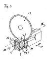
- the center slots 3 are in the embodiment of Fig. 1 arranged symmetrically to the central longitudinal axis III of the metal strip. As in Fig. 3 shown, their length l 2 is chosen so large that the center slots 3 extend into the legs 9 of the U-profile 10 formed from the metal strip. The extension of the central slots 3 in the legs 9 of the U-profile 10 but only briefly in relation to their length l. 2
- the center slots 3 are not symmetrical to the central longitudinal axis III of the metal strip, but arranged to a longitudinal axis IV parallel thereto.
- the edge slots 1 have in this embodiment, on such a length l 1 , that overlap the edge slots with the center slots 3 only slightly in the transverse direction II of the metal strip. Accordingly, from the in Fig. 2 left edge to the strip interior extending edge slots 1 a shorter length than that of the in Fig. 2 The size of the overlap corresponds to that of the embodiment of FIG Fig. 1 ,
- partitions 6 are provided only on the side of the long edge slots 1 of the metal strip, so only starting from the right edge in Fig. 2 .
- the non-severed region 8 between the band inside ends 7 and the respective opposite wedge tip 5 of the center slots 3 also has here only a short length a of preferably less than 0.5 cm, in particular according to the embodiment of about 0.4 cm. Due to the asymmetrical arrangement of the center slots 3, the distance of the other wedge tips 5 of the center slots 3 from the left edge 2 of the metal strip also only a small size, in particular in the illustrated embodiment of about 0.5 cm. Even without severing on the left side of the metal strip, therefore, the described advantages arise when cutting this metal strip. However, it is also possible with an asymmetrical arrangement of the center slots 3, 6 to provide dividers on both sides of the metal strip, so starting from two edges.
- Fig. 3 shows the cutting through a equipped with a metal strip according to the invention clamping profile.
- the metal strip is bent into a U-profile 10 and covered with a sealing material 11.
- the clamping profile has a sealing lip 12.
- a cutting disc 13 is used in the illustrated example, the drive is not shown.
- the cutting wheel can be automatically positioned at one of the center slots 3.
- a severing of the clamping profile at a point at which only short not severed areas, namely the areas 8 between the wedge tips 5 of the central slot 3 and the two opposite partitions 6 are present.
- These areas 8 have only a short length a of about 0.4 cm. It is therefore only a small amount of energy required to sever the clamping profile, resulting in a slight deterioration of the clamping profile.
- 3 smooth cut surfaces can be obtained when severing the clamping profile in the region of a central slot.
Landscapes
- Engineering & Computer Science (AREA)
- Mechanical Engineering (AREA)
- Seal Device For Vehicle (AREA)
- Gasket Seals (AREA)
- Clamps And Clips (AREA)
- Package Frames And Binding Bands (AREA)
Priority Applications (1)
| Application Number | Priority Date | Filing Date | Title |
|---|---|---|---|
| PL06003293T PL1693237T5 (pl) | 2005-02-22 | 2006-02-17 | Taśma metalowa jako wkładka dla pasów ozdobnych lub uszczelniających |
Applications Claiming Priority (1)
| Application Number | Priority Date | Filing Date | Title |
|---|---|---|---|
| DE200520002832 DE202005002832U1 (de) | 2005-02-22 | 2005-02-22 | Metallband als Einlage für Zier- oder Dichtstreifen |
Publications (4)
| Publication Number | Publication Date |
|---|---|
| EP1693237A2 EP1693237A2 (de) | 2006-08-23 |
| EP1693237A3 EP1693237A3 (de) | 2010-02-10 |
| EP1693237B1 EP1693237B1 (de) | 2013-09-25 |
| EP1693237B2 true EP1693237B2 (de) | 2019-09-25 |
Family
ID=34609796
Family Applications (1)
| Application Number | Title | Priority Date | Filing Date |
|---|---|---|---|
| EP06003293.5A Expired - Lifetime EP1693237B2 (de) | 2005-02-22 | 2006-02-17 | Metallband als Einlage für Zier- oder Dichtstreifen |
Country Status (4)
| Country | Link |
|---|---|
| US (1) | US7517590B2 (pl) |
| EP (1) | EP1693237B2 (pl) |
| DE (1) | DE202005002832U1 (pl) |
| PL (1) | PL1693237T5 (pl) |
Families Citing this family (19)
| Publication number | Priority date | Publication date | Assignee | Title |
|---|---|---|---|---|
| US20090060656A1 (en) * | 2007-08-28 | 2009-03-05 | Allied Tube & Conduit Corporation | Paver edging device and method |
| US8205390B2 (en) * | 2009-02-26 | 2012-06-26 | Henniges Automotive Sealing Systems North America, Inc. | Mechanically stiffened weatherseal carrier |
| JP5556611B2 (ja) * | 2009-12-25 | 2014-07-23 | 豊田合成株式会社 | インサートの製造方法及びそのインサートを有する長尺成形品の製造方法 |
| US9073422B2 (en) | 2012-08-02 | 2015-07-07 | Fca Us Llc | Weatherstrip assembly and method of manufacturing the same |
| US9708816B2 (en) | 2014-05-30 | 2017-07-18 | Sacks Industrial Corporation | Stucco lath and method of manufacture |
| US9752323B2 (en) | 2015-07-29 | 2017-09-05 | Sacks Industrial Corporation | Light-weight metal stud and method of manufacture |
| DE102015120415B4 (de) * | 2015-11-25 | 2022-12-29 | Cqlt Saargummi Technologies S.À.R.L. | Verstärkungsprofil |
| DE102016114657A1 (de) | 2016-08-08 | 2018-02-08 | Rehau Ag + Co | Dichtungsprofil für ein Kraftfahrzeug oder Kraftfahrzeugbauteil sowie Verfahren zur Befestigung eines Dichtungsprofils |
| US9797142B1 (en) | 2016-09-09 | 2017-10-24 | Sacks Industrial Corporation | Lath device, assembly and method |
| DE102016125250B4 (de) | 2016-12-21 | 2021-10-07 | Webasto SE | Verfahren zur Herstellung von Dichtungen |
| JP7055465B2 (ja) | 2017-08-14 | 2022-04-18 | ストラクタ ワイヤー ユーエルシー | 可変長金属スタッド |
| US11351593B2 (en) | 2018-09-14 | 2022-06-07 | Structa Wire Ulc | Expanded metal formed using rotary blades and rotary blades to form such |
| DE202019106738U1 (de) * | 2019-12-03 | 2021-03-04 | Bfc Fahrzeugteile Gmbh | Metallband |
| DE102020101975A1 (de) | 2020-01-28 | 2021-07-29 | Bfc Fahrzeugteile Gmbh | Metallband |
| JP2022048510A (ja) * | 2020-09-15 | 2022-03-28 | 豊田合成株式会社 | ガラスラン |
| DE202021104735U1 (de) * | 2021-09-02 | 2021-10-04 | Bfc Fahrzeugteile Gmbh | Metallband |
| DE102023118748B3 (de) | 2023-07-14 | 2024-03-07 | STG Stanztechnik GmbH & Co. KG | Formkörper aus einer spritzfähigen Masse mit wenigstens einer Einlage |
| DE202023107375U1 (de) | 2023-07-14 | 2024-01-12 | STG Stanztechnik GmbH & Co. KG | Einlage für einen Formkörper aus einer spritzfähigen Masse sowie Formkörper |
| DE102023125063A1 (de) * | 2023-09-15 | 2025-03-20 | STG Stanztechnik GmbH & Co. KG | Verfahren zur Herstellung eines mit geschlitzten Öffnungen versehenen, endlosen Metallbandes, ein Metallband sowie einen Formkörper |
Citations (3)
| Publication number | Priority date | Publication date | Assignee | Title |
|---|---|---|---|---|
| AU4099485A (en) † | 1984-04-11 | 1985-10-17 | Toyoda Gosei Co. Ltd. | Trim strip core |
| EP0252659A1 (en) † | 1986-06-26 | 1988-01-13 | Silent Channel Products Limited | A core for a strip structure |
| EP0707995A1 (en) † | 1994-10-20 | 1996-04-24 | Draftex Industries Limited | Reinforcement for sealing, guiding and trimming strips |
Family Cites Families (7)
| Publication number | Priority date | Publication date | Assignee | Title |
|---|---|---|---|---|
| US4745665A (en) * | 1987-03-30 | 1988-05-24 | Hilsenbeck Henry K | Elongated clips having a metal core and metal core for such clips |
| GB2209045B (en) * | 1987-08-25 | 1991-06-05 | Silent Channel Prod Ltd | A core for a strip structure |
| DE4003622C2 (de) * | 1990-02-07 | 1995-05-24 | Bfc Buero Fahrzeugtech | Metallband als Einlage für Zier- und Dichtstreifen |
| US5199142A (en) * | 1991-09-04 | 1993-04-06 | The Gem City Engineering Co. | Production of expanded metal strip for reinforcing a resilient product |
| US5783312A (en) * | 1996-12-19 | 1998-07-21 | The Gem City Engineering Co. | Expanded metal strip for reinforcing a resilient product |
| US6079160A (en) * | 1998-01-13 | 2000-06-27 | Arrowhead Industries Corporation | Core metal insert with stagger and offset backbone |
| US6447928B2 (en) * | 1998-10-01 | 2002-09-10 | Gem City Engineering Company | Process of manufacturing a core metal insert |
-
2005
- 2005-02-22 DE DE200520002832 patent/DE202005002832U1/de not_active Expired - Lifetime
- 2005-11-15 US US11/274,077 patent/US7517590B2/en not_active Expired - Lifetime
-
2006
- 2006-02-17 EP EP06003293.5A patent/EP1693237B2/de not_active Expired - Lifetime
- 2006-02-17 PL PL06003293T patent/PL1693237T5/pl unknown
Patent Citations (4)
| Publication number | Priority date | Publication date | Assignee | Title |
|---|---|---|---|---|
| AU4099485A (en) † | 1984-04-11 | 1985-10-17 | Toyoda Gosei Co. Ltd. | Trim strip core |
| EP0252659A1 (en) † | 1986-06-26 | 1988-01-13 | Silent Channel Products Limited | A core for a strip structure |
| EP0707995A1 (en) † | 1994-10-20 | 1996-04-24 | Draftex Industries Limited | Reinforcement for sealing, guiding and trimming strips |
| DE69501998T2 (de) † | 1994-10-20 | 1998-07-30 | Draftex Ind Ltd | Armierung für Dichtungsstreifen, Führungsleisten und Randleisten |
Also Published As
| Publication number | Publication date |
|---|---|
| US7517590B2 (en) | 2009-04-14 |
| DE202005002832U1 (de) | 2005-05-19 |
| PL1693237T5 (pl) | 2020-07-27 |
| EP1693237B1 (de) | 2013-09-25 |
| US20060185132A1 (en) | 2006-08-24 |
| PL1693237T3 (pl) | 2014-03-31 |
| EP1693237A3 (de) | 2010-02-10 |
| EP1693237A2 (de) | 2006-08-23 |
Similar Documents
| Publication | Publication Date | Title |
|---|---|---|
| EP1693237B2 (de) | Metallband als Einlage für Zier- oder Dichtstreifen | |
| DE69501998T2 (de) | Armierung für Dichtungsstreifen, Führungsleisten und Randleisten | |
| DE2937454C2 (de) | Verbundprofil, insbesondere für Fenster, Türen und Fassaden sowie Verfahren zum Herstellen des Verbundprofils | |
| DE3814448C2 (pl) | ||
| DE2926446C2 (de) | An einem Kantenbesatz vorgesehene oder als Kantenbesatz zu verwendende und einen Steg U-förmig umgreifende Klemmleiste | |
| EP3924198B1 (de) | Metallband | |
| DE69005987T2 (de) | Dichtung, Vorrichtung und Verfahren zur ihrer Herstellung. | |
| EP0290536B2 (de) | Verfahren zur herstellung eines fensterprofiles mit einem dichtungselement | |
| DE3390257C2 (pl) | ||
| WO2023031357A1 (de) | Metallband | |
| DE2302877C3 (de) | Verfahren zum Herstellen von Metalleinlagen für profilierte und flexible Bänder mit einer Umhüllung | |
| DE2444859A1 (de) | Verfahren und vorrichtung zur herstellung von streckmetall-gitterplatten fuer blei-saeure-akkumulatoren | |
| EP1666295B2 (de) | Metallband als Einlage für Zier- oder Dichtstreifen | |
| EP0441287B1 (de) | Metallband als Einlage für Zier- und Dichtstreife | |
| EP3380351B1 (de) | Verstärkungsprofil | |
| DE69106593T2 (de) | Metallische Armierung für Dichtungsband oder dergleichen und Verfahren zu seiner Herstellung. | |
| EP1464526A2 (de) | Metallband als Einlage für Zier- oder Dichtstreifen | |
| WO2016202534A1 (de) | Verfahren zum herstellen eines kunststoffantriebskabels, kunststoffantriebskabel und formzahnrad | |
| DE3033015C2 (de) | Antriebsriemen mit Vierkantprofil aus Gummi oder gummiartigem Werkstoff sowie Verfahren und Vorrichtung zu seiner Herstellung | |
| DE4030922C2 (de) | Klemmprofilanordnung | |
| DE2342191A1 (de) | Vorrichtung zur fortlaufenden ausbildung einer isolierten platte | |
| DE9001847U1 (de) | Metallband als Einlage für Zier- und Dichtleisten | |
| AT515667B1 (de) | Sägekette und Verfahren zur Herstellung eines Verbindungsgliedes für eine Sägekette | |
| DE202022101561U1 (de) | Metallband | |
| WO2025031637A1 (de) | Metallband, dicht-, zier- oder randstreifen mit einem metallband als einlage und verfahren zu dessen herstellung |
Legal Events
| Date | Code | Title | Description |
|---|---|---|---|
| PUAI | Public reference made under article 153(3) epc to a published international application that has entered the european phase |
Free format text: ORIGINAL CODE: 0009012 |
|
| AK | Designated contracting states |
Kind code of ref document: A2 Designated state(s): AT BE BG CH CY CZ DE DK EE ES FI FR GB GR HU IE IS IT LI LT LU LV MC NL PL PT RO SE SI SK TR |
|
| AX | Request for extension of the european patent |
Extension state: AL BA HR MK YU |
|
| RAP1 | Party data changed (applicant data changed or rights of an application transferred) |
Owner name: BFC BUERO- UND FAHRZEUGTECHNIK GMBH & CO. PROD. KG |
|
| PUAL | Search report despatched |
Free format text: ORIGINAL CODE: 0009013 |
|
| AK | Designated contracting states |
Kind code of ref document: A3 Designated state(s): AT BE BG CH CY CZ DE DK EE ES FI FR GB GR HU IE IS IT LI LT LU LV MC NL PL PT RO SE SI SK TR |
|
| AX | Request for extension of the european patent |
Extension state: AL BA HR MK YU |
|
| 17P | Request for examination filed |
Effective date: 20100809 |
|
| 17Q | First examination report despatched |
Effective date: 20100907 |
|
| AKX | Designation fees paid |
Designated state(s): AT BE BG CH CY CZ DE DK EE ES FI FR GB GR HU IE IS IT LI LT LU LV MC NL PL PT RO SE SI SK TR |
|
| RAP1 | Party data changed (applicant data changed or rights of an application transferred) |
Owner name: BFC FAHRZEUGTEILE GMBH |
|
| GRAP | Despatch of communication of intention to grant a patent |
Free format text: ORIGINAL CODE: EPIDOSNIGR1 |
|
| INTG | Intention to grant announced |
Effective date: 20130412 |
|
| GRAS | Grant fee paid |
Free format text: ORIGINAL CODE: EPIDOSNIGR3 |
|
| GRAA | (expected) grant |
Free format text: ORIGINAL CODE: 0009210 |
|
| AK | Designated contracting states |
Kind code of ref document: B1 Designated state(s): AT BE BG CH CY CZ DE DK EE ES FI FR GB GR HU IE IS IT LI LT LU LV MC NL PL PT RO SE SI SK TR |
|
| REG | Reference to a national code |
Ref country code: GB Ref legal event code: FG4D Free format text: NOT ENGLISH |
|
| REG | Reference to a national code |
Ref country code: CH Ref legal event code: EP |
|
| REG | Reference to a national code |
Ref country code: AT Ref legal event code: REF Ref document number: 633562 Country of ref document: AT Kind code of ref document: T Effective date: 20131015 |
|
| REG | Reference to a national code |
Ref country code: IE Ref legal event code: FG4D Free format text: LANGUAGE OF EP DOCUMENT: GERMAN |
|
| REG | Reference to a national code |
Ref country code: DE Ref legal event code: R096 Ref document number: 502006013224 Country of ref document: DE Effective date: 20131121 |
|
| PG25 | Lapsed in a contracting state [announced via postgrant information from national office to epo] |
Ref country code: SE Free format text: LAPSE BECAUSE OF FAILURE TO SUBMIT A TRANSLATION OF THE DESCRIPTION OR TO PAY THE FEE WITHIN THE PRESCRIBED TIME-LIMIT Effective date: 20130925 Ref country code: LT Free format text: LAPSE BECAUSE OF FAILURE TO SUBMIT A TRANSLATION OF THE DESCRIPTION OR TO PAY THE FEE WITHIN THE PRESCRIBED TIME-LIMIT Effective date: 20130925 |
|
| REG | Reference to a national code |
Ref country code: NL Ref legal event code: VDEP Effective date: 20130925 |
|
| REG | Reference to a national code |
Ref country code: LT Ref legal event code: MG4D |
|
| PG25 | Lapsed in a contracting state [announced via postgrant information from national office to epo] |
Ref country code: SI Free format text: LAPSE BECAUSE OF FAILURE TO SUBMIT A TRANSLATION OF THE DESCRIPTION OR TO PAY THE FEE WITHIN THE PRESCRIBED TIME-LIMIT Effective date: 20130925 Ref country code: FI Free format text: LAPSE BECAUSE OF FAILURE TO SUBMIT A TRANSLATION OF THE DESCRIPTION OR TO PAY THE FEE WITHIN THE PRESCRIBED TIME-LIMIT Effective date: 20130925 Ref country code: GR Free format text: LAPSE BECAUSE OF FAILURE TO SUBMIT A TRANSLATION OF THE DESCRIPTION OR TO PAY THE FEE WITHIN THE PRESCRIBED TIME-LIMIT Effective date: 20131226 Ref country code: LV Free format text: LAPSE BECAUSE OF FAILURE TO SUBMIT A TRANSLATION OF THE DESCRIPTION OR TO PAY THE FEE WITHIN THE PRESCRIBED TIME-LIMIT Effective date: 20130925 |
|
| PG25 | Lapsed in a contracting state [announced via postgrant information from national office to epo] |
Ref country code: EE Free format text: LAPSE BECAUSE OF FAILURE TO SUBMIT A TRANSLATION OF THE DESCRIPTION OR TO PAY THE FEE WITHIN THE PRESCRIBED TIME-LIMIT Effective date: 20130925 Ref country code: NL Free format text: LAPSE BECAUSE OF FAILURE TO SUBMIT A TRANSLATION OF THE DESCRIPTION OR TO PAY THE FEE WITHIN THE PRESCRIBED TIME-LIMIT Effective date: 20130925 Ref country code: SK Free format text: LAPSE BECAUSE OF FAILURE TO SUBMIT A TRANSLATION OF THE DESCRIPTION OR TO PAY THE FEE WITHIN THE PRESCRIBED TIME-LIMIT Effective date: 20130925 Ref country code: IS Free format text: LAPSE BECAUSE OF FAILURE TO SUBMIT A TRANSLATION OF THE DESCRIPTION OR TO PAY THE FEE WITHIN THE PRESCRIBED TIME-LIMIT Effective date: 20140125 Ref country code: RO Free format text: LAPSE BECAUSE OF FAILURE TO SUBMIT A TRANSLATION OF THE DESCRIPTION OR TO PAY THE FEE WITHIN THE PRESCRIBED TIME-LIMIT Effective date: 20130925 Ref country code: CZ Free format text: LAPSE BECAUSE OF FAILURE TO SUBMIT A TRANSLATION OF THE DESCRIPTION OR TO PAY THE FEE WITHIN THE PRESCRIBED TIME-LIMIT Effective date: 20130925 |
|
| PG25 | Lapsed in a contracting state [announced via postgrant information from national office to epo] |
Ref country code: CY Free format text: LAPSE BECAUSE OF FAILURE TO SUBMIT A TRANSLATION OF THE DESCRIPTION OR TO PAY THE FEE WITHIN THE PRESCRIBED TIME-LIMIT Effective date: 20130925 Ref country code: ES Free format text: LAPSE BECAUSE OF FAILURE TO SUBMIT A TRANSLATION OF THE DESCRIPTION OR TO PAY THE FEE WITHIN THE PRESCRIBED TIME-LIMIT Effective date: 20130925 |
|
| REG | Reference to a national code |
Ref country code: DE Ref legal event code: R026 Ref document number: 502006013224 Country of ref document: DE |
|
| PG25 | Lapsed in a contracting state [announced via postgrant information from national office to epo] |
Ref country code: PT Free format text: LAPSE BECAUSE OF FAILURE TO SUBMIT A TRANSLATION OF THE DESCRIPTION OR TO PAY THE FEE WITHIN THE PRESCRIBED TIME-LIMIT Effective date: 20140127 |
|
| PLBI | Opposition filed |
Free format text: ORIGINAL CODE: 0009260 |
|
| PLAX | Notice of opposition and request to file observation + time limit sent |
Free format text: ORIGINAL CODE: EPIDOSNOBS2 |
|
| 26 | Opposition filed |
Opponent name: STG STANZTECHNIK GMBH & CO.KG Effective date: 20140625 |
|
| PG25 | Lapsed in a contracting state [announced via postgrant information from national office to epo] |
Ref country code: IT Free format text: LAPSE BECAUSE OF FAILURE TO SUBMIT A TRANSLATION OF THE DESCRIPTION OR TO PAY THE FEE WITHIN THE PRESCRIBED TIME-LIMIT Effective date: 20130925 |
|
| BERE | Be: lapsed |
Owner name: BFC FAHRZEUGTEILE G.M.B.H. Effective date: 20140228 |
|
| REG | Reference to a national code |
Ref country code: DE Ref legal event code: R026 Ref document number: 502006013224 Country of ref document: DE Effective date: 20140625 |
|
| PG25 | Lapsed in a contracting state [announced via postgrant information from national office to epo] |
Ref country code: DK Free format text: LAPSE BECAUSE OF FAILURE TO SUBMIT A TRANSLATION OF THE DESCRIPTION OR TO PAY THE FEE WITHIN THE PRESCRIBED TIME-LIMIT Effective date: 20130925 Ref country code: LU Free format text: LAPSE BECAUSE OF FAILURE TO SUBMIT A TRANSLATION OF THE DESCRIPTION OR TO PAY THE FEE WITHIN THE PRESCRIBED TIME-LIMIT Effective date: 20140217 Ref country code: MC Free format text: LAPSE BECAUSE OF FAILURE TO SUBMIT A TRANSLATION OF THE DESCRIPTION OR TO PAY THE FEE WITHIN THE PRESCRIBED TIME-LIMIT Effective date: 20130925 |
|
| REG | Reference to a national code |
Ref country code: CH Ref legal event code: PL |
|
| GBPC | Gb: european patent ceased through non-payment of renewal fee |
Effective date: 20140217 |
|
| PG25 | Lapsed in a contracting state [announced via postgrant information from national office to epo] |
Ref country code: CH Free format text: LAPSE BECAUSE OF NON-PAYMENT OF DUE FEES Effective date: 20140228 Ref country code: LI Free format text: LAPSE BECAUSE OF NON-PAYMENT OF DUE FEES Effective date: 20140228 |
|
| REG | Reference to a national code |
Ref country code: IE Ref legal event code: MM4A |
|
| PLAF | Information modified related to communication of a notice of opposition and request to file observations + time limit |
Free format text: ORIGINAL CODE: EPIDOSCOBS2 |
|
| PG25 | Lapsed in a contracting state [announced via postgrant information from national office to epo] |
Ref country code: GB Free format text: LAPSE BECAUSE OF NON-PAYMENT OF DUE FEES Effective date: 20140217 Ref country code: BE Free format text: LAPSE BECAUSE OF NON-PAYMENT OF DUE FEES Effective date: 20140228 Ref country code: IE Free format text: LAPSE BECAUSE OF NON-PAYMENT OF DUE FEES Effective date: 20140217 |
|
| PLBB | Reply of patent proprietor to notice(s) of opposition received |
Free format text: ORIGINAL CODE: EPIDOSNOBS3 |
|
| REG | Reference to a national code |
Ref country code: AT Ref legal event code: MM01 Ref document number: 633562 Country of ref document: AT Kind code of ref document: T Effective date: 20140217 |
|
| PG25 | Lapsed in a contracting state [announced via postgrant information from national office to epo] |
Ref country code: AT Free format text: LAPSE BECAUSE OF NON-PAYMENT OF DUE FEES Effective date: 20140217 |
|
| REG | Reference to a national code |
Ref country code: FR Ref legal event code: PLFP Year of fee payment: 11 |
|
| PG25 | Lapsed in a contracting state [announced via postgrant information from national office to epo] |
Ref country code: BG Free format text: LAPSE BECAUSE OF FAILURE TO SUBMIT A TRANSLATION OF THE DESCRIPTION OR TO PAY THE FEE WITHIN THE PRESCRIBED TIME-LIMIT Effective date: 20130925 |
|
| RIC2 | Information provided on ipc code assigned after grant |
Ipc: B60J 10/18 20160101AFI20160615BHEP |
|
| PG25 | Lapsed in a contracting state [announced via postgrant information from national office to epo] |
Ref country code: HU Free format text: LAPSE BECAUSE OF FAILURE TO SUBMIT A TRANSLATION OF THE DESCRIPTION OR TO PAY THE FEE WITHIN THE PRESCRIBED TIME-LIMIT; INVALID AB INITIO Effective date: 20060217 |
|
| APBM | Appeal reference recorded |
Free format text: ORIGINAL CODE: EPIDOSNREFNO |
|
| APBP | Date of receipt of notice of appeal recorded |
Free format text: ORIGINAL CODE: EPIDOSNNOA2O |
|
| APAH | Appeal reference modified |
Free format text: ORIGINAL CODE: EPIDOSCREFNO |
|
| APBQ | Date of receipt of statement of grounds of appeal recorded |
Free format text: ORIGINAL CODE: EPIDOSNNOA3O |
|
| REG | Reference to a national code |
Ref country code: FR Ref legal event code: PLFP Year of fee payment: 12 |
|
| REG | Reference to a national code |
Ref country code: FR Ref legal event code: PLFP Year of fee payment: 13 |
|
| APBU | Appeal procedure closed |
Free format text: ORIGINAL CODE: EPIDOSNNOA9O |
|
| RIC2 | Information provided on ipc code assigned after grant |
Ipc: B60R 13/06 20060101ALI20190502BHEP Ipc: F16B 5/12 20060101ALI20190502BHEP Ipc: B60J 10/18 20160101AFI20190502BHEP Ipc: B60R 13/04 20060101ALI20190502BHEP |
|
| PUAH | Patent maintained in amended form |
Free format text: ORIGINAL CODE: 0009272 |
|
| STAA | Information on the status of an ep patent application or granted ep patent |
Free format text: STATUS: PATENT MAINTAINED AS AMENDED |
|
| 27A | Patent maintained in amended form |
Effective date: 20190925 |
|
| AK | Designated contracting states |
Kind code of ref document: B2 Designated state(s): AT BE BG CH CY CZ DE DK EE ES FI FR GB GR HU IE IS IT LI LT LU LV MC NL PL PT RO SE SI SK TR |
|
| REG | Reference to a national code |
Ref country code: DE Ref legal event code: R102 Ref document number: 502006013224 Country of ref document: DE |
|
| PGFP | Annual fee paid to national office [announced via postgrant information from national office to epo] |
Ref country code: FR Payment date: 20250221 Year of fee payment: 20 Ref country code: PL Payment date: 20250207 Year of fee payment: 20 |
|
| PGFP | Annual fee paid to national office [announced via postgrant information from national office to epo] |
Ref country code: TR Payment date: 20250210 Year of fee payment: 20 |
|
| PGFP | Annual fee paid to national office [announced via postgrant information from national office to epo] |
Ref country code: DE Payment date: 20250428 Year of fee payment: 20 |
|
| REG | Reference to a national code |
Ref country code: DE Ref legal event code: R071 Ref document number: 502006013224 Country of ref document: DE |