EP1693241A2 - Conduite de remplissage pour réservoir de carburant - Google Patents
Conduite de remplissage pour réservoir de carburant Download PDFInfo
- Publication number
- EP1693241A2 EP1693241A2 EP06250846A EP06250846A EP1693241A2 EP 1693241 A2 EP1693241 A2 EP 1693241A2 EP 06250846 A EP06250846 A EP 06250846A EP 06250846 A EP06250846 A EP 06250846A EP 1693241 A2 EP1693241 A2 EP 1693241A2
- Authority
- EP
- European Patent Office
- Prior art keywords
- filler neck
- low
- fuel
- component
- permeation layer
- Prior art date
- Legal status (The legal status is an assumption and is not a legal conclusion. Google has not performed a legal analysis and makes no representation as to the accuracy of the status listed.)
- Granted
Links
Images


Classifications
-
- B—PERFORMING OPERATIONS; TRANSPORTING
- B60—VEHICLES IN GENERAL
- B60K—ARRANGEMENT OR MOUNTING OF PROPULSION UNITS OR OF TRANSMISSIONS IN VEHICLES; ARRANGEMENT OR MOUNTING OF PLURAL DIVERSE PRIME-MOVERS IN VEHICLES; AUXILIARY DRIVES FOR VEHICLES; INSTRUMENTATION OR DASHBOARDS FOR VEHICLES; ARRANGEMENTS IN CONNECTION WITH COOLING, AIR INTAKE, GAS EXHAUST OR FUEL SUPPLY OF PROPULSION UNITS IN VEHICLES
- B60K15/00—Arrangement in connection with fuel supply of combustion engines or other fuel consuming energy converters, e.g. fuel cells; Mounting or construction of fuel tanks
- B60K15/03—Fuel tanks
- B60K15/04—Tank inlets
Definitions
- the present disclosure relates to fuel systems, and particularly to fuel tank filler necks. More particularly, the present disclosure relates to a component coupled to a fuel tank filler neck and retained in a fuel-conducting passageway formed in the filler neck.
- a component such as an inlet cup or inlet check valve is retained in a fixed position in a filler neck by bonding a low-permeation layer of the component to a low-permeation layer of the filler neck.
- the layers are made of the same or similar materials.
- Fig. 1 is a perspective view of a fuel tank coupled to a tank filler neck including an inlet cup and closure cap at an outer end of the filler neck and an inlet check valve at an inner end of the filler neck in accordance with the present disclosure;
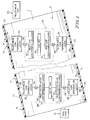
- Fig. 2 is an enlarged diagrammatic view of the filler neck of Fig. 1 showing that (1) a low-permeation layer in the inlet check valve is bonded to a low-permeation layer in the filler neck to retain the inlet check valve in a fixed position in the filler neck and (2) a low-permeation layer in the inlet cup is bonded to a low-permeation layer in the filler neck to retain the inlet cup in a fixed position in the filler neck;
- Fig. 3 is a perspective assembly view, with portions broken away, showing various layers included in the filler neck and various layers included in the inlet cup before the inlet cup is bonded to the filler neck;
- Fig. 4 is an enlarged sectional view showing mating and bonding of the inlet cup low-permeation layer and the filler neck low-permeation layer before a closure cap is coupled to the filler neck to close an open mouth of the filler neck;
- Fig. 5 is a view similar to Fig. 4 showing a closure cap coupled to the filler neck to define a closed chamber in the filler neck and showing that a "leak path" (LP), which leak path may be established between dissimilar materials comprising the inlet cup, both originates and terminates in the closed chamber to block discharge of liquid fuel and fuel vapor leakage to the surroundings outside the filler neck while the closure cap is mounted on the filler neck.
- LP "leak path”
- a vehicle fuel system 10 comprises a fuel tank 12, a filler neck 14 having a lower end 16 coupled to fuel tank 12 and an upper end 18, and a removable closure cap 20 coupled to upper end 18 of filler neck 14 to close an open mouth 22 formed in the upper end of filler neck 14 as shown, for example, in Fig. 1.
- Vehicle fuel system 10 also comprises filler neck components such as an inlet check valve 24 and an inlet cup 26 coupled to filler neck 14 as shown diagrammatically in Fig. 2.
- Inlet check valve 24 is configured to lie in a fuel-conducting passageway 15 formed in filler neck 14 and regulate flow of liquid fuel and fuel vapor therethrough.
- a fuel-conducting conduit 29 formed in inlet check valve 24 includes a "one-way" valve member 31 that is slidable in a fuel-conducting conduit 29 formed in a valve base 33 between conduit-closing position shown in Fig. 1 and a conduit-opening position (not shown).
- liquid fuel discharged into an "open" filler neck 14 by a fuel-dispensing pump nozzle contacts and moves one-way valve member 31 inwardly against a yieldable biasing spring 32 located in valve base 33 to assume the opened position so that liquid fuel can flow past the one-way valve member 31 and through fuel-conducting conduit 29 into a fuel reservoir 134 provided in an interior region 35 of fuel tank 12.
- a fuel-dispensing pump nozzle not shown
- a fuel-dispensing pump nozzle contacts and moves one-way valve member 31 inwardly against a yieldable biasing spring 32 located in valve base 33 to assume the opened position so that liquid fuel can flow past the one-way valve member 31 and through fuel-conducting conduit 29 into a fuel reservoir 134 provided in an interior region 35 of fuel tank 12.
- Inlet cup 26 includes a mount 38 and a nozzle restrictor 40 coupled to mount 38 and formed to include an aperture 42 as shown, for example, in Figs. 1 and 3-5.
- Mount 38 is coupled to outer end 18 of filler neck 14 and sized to receive an inner portion of closure cap 20 therein as suggested in Figs. 1 and 5.
- Aperture 42 is sized to receive a fuel-dispensing portion of a pump nozzle (not shown) therein during tank refueling.
- filler neck 14 comprises a side wall 23 and a filler neck low-permeation layer 25 coupled to an interior surface 28 of side wall 23. It is within the scope of the present disclosure to mate a low-permeation layer provided on an exterior portion of a filler neck component (e.g., inlet check valve 24 or inlet cup 26) with a low-permeation layer 25 provided on an interior surface 28 of filler neck 14.
- a filler neck component e.g., inlet check valve 24 or inlet cup 26
- inlet check valve 24 includes a valve unit 30 and an inlet check valve (component) low-permeation layer 32 coupled to filler neck low-permeation layer 25 at bond joint 34 to retain valve unit 30 in a fixed position in fuel-conducting passageway 15 S of lower end 16 of filler neck 14.
- a "low-emission" union of filler neck 14 and inlet check valve 24 is established at bond joint 34 since low-permeation layers 25 and 32, in an illustrative embodiment, are made of substantially the same material and bonded to one another.
- inlet check valve 24 is coupled to filler neck 14 by bonding inlet check valve low-permeation layer 32 on valve base 33 of valve unit 30 to filler neck low-permeation layer 25 on filler neck 14.
- Valve unit 30 comprises one-way valve member 31, spring 32, and valve base 33.
- inlet cup 26 includes a cup unit 36 and an inlet cup (component) low-permeation layer 37 coupled to filler neck low-permeation layer 25 at bond joint 39 to retain cup unit 36 in a fixed position in fuel-conducting passageway 15 of upper end 18 of filler neck 14.
- a low-emission union of filler neck 14 and inlet cup 26 is established at bond joint 39 since low-permeation layers 25 and 37, in an illustrative embodiment, are made of the same material and bonded to one another.
- inlet cup 26 is coupled to filler neck 14 by bonding inlet cup low-permeation layer 37 on cup unit 36 to filler neck low-permeation layer 25 on filler neck 14.
- Cup unit 36 comprises nozzle restrictor 40, threaded restrictor anchor 64, and inlet cup low-permeation layer 37, as shown best in Fig. 4.
- Nozzle restrictor 40 and threaded restrictor anchor 64 cooperate to define a base 41 to which inlet cup low-permeation layer 25 is coupled.
- each of low-permeation layers 25, 32, and 37 is made of polyarylamide (PAA). It is within the scope of this disclosure to use other suitable materials to form layers 25, 32, and 37 such as, for example, semiaromatic polyamide (PPA), polyphenylene sulfide alloy (PPS), and polybutylene terephthalate (PBT).
- PPA polyarylamide
- PPS polyphenylene sulfide alloy
- PBT polybutylene terephthalate
- filler neck 14 comprises a side wall 23 including an outer sleeve 71 providing an exterior surface 72 and an inner sleeve 73 providing interior surface 28.
- Outer sleeve 71 surrounds inner sleeve 73 and cooperates with inner sleeve 73 to define side wall 23.
- Filler neck low-permeation layer 25 of inlet cup 26 is appended to interior surface 28 of inner sleeve 73 as shown best in Fig. 4.
- Each of outer and inner sleeves 71, 73 is made of a suitable plastics material in the illustrated embodiment.
- filler neck 14 is a multi-layer tubular member.
- mount 38 of inlet cup 26 includes threaded restrictor anchor 64 and inlet cup low-permeation layer 37.
- Restrictor anchor 64 includes a restrictor support ring 66 and a cap-mount sleeve 68.
- Restrictor support ring 66 is coupled to nozzle restrictor 40 and to an interior surface 27 of filler neck low-permeation layer 25.
- Nozzle restrictor 40 is formed to include aperture means 42 for receiving a small-diameter unleaded fuel-dispensing pump nozzle therein so that unleaded fuel can be dispensed into fuel-conducting passageway 15.
- Cap-mount sleeve 68 is coupled to restrictor support ring 66 and arranged to lie inside an interior region 15 defined by filler neck low-permeation layer 25 to define an annular space therebetween.
- Inlet cup low-permeation layer 37 includes a cylindrical inner section 371 located in that annular space and a cylindrical outer section 372 located outside that annular space and formed to define an annular rim 70 as suggested in Fig. 4.
- Bond joint 39 is established between interior surface 27 of filler neck low-permeation layer 25 and an exterior surface 65 of cylindrical inner section 371 of inlet cup low-permeation layer 37.
- low-permeation layer 37 of inlet cup 26 By bonding low-permeation layer 37 of inlet cup 26 to low-permeation layer 25 of filler neck 14 without using mechanical locks or clamps or additional sealing members, those layers 25, 37 are unified to produce a monolithic element providing a liquid-and-vapor barrier to block leakage of liquid fuel and fuel vapor (or other hydrocarbon emissions) along a path between layers 25, 37. It is thus unnecessary to deploy any O-ring seal or gasket between layers 25, 37 to minimize discharge of emissions from the filler neck to the surroundings along or across a joint or space between a filler neck and an inlet cup mounted in the filler neck.
- the barrier or low-permeation layers 25, 37 of filler neck 14 and inlet cup 26 are made of the same (or similar) material and are bonded to one another to form a low-emission union therebetween.
- a bonded joint can be achieved through a welding operation (e.g., hot plate, sonic, spin, vibration, or laser) or by overmolding (e.g., blow molding).
- Closure cap 20 includes a handgrip 101, a threaded portion 102 configured to mate with and engage threads 69 formed on cap-mount sleeve 68, an annular flange 103, and an annular seal 104 coupled to annular flange 103 and arranged to be compressed between rim 70 on filler neck 14 and annular flange 103 on closure cap 20 to establish a sealed interface between filler neck 14 and closure cap 20.
- LP leak path
- a filler neck 12 comprises a side wall 23 and a filler neck low-permeation layer 25 coupled to an interior surface 28 of side wall 23 and configured to define a boundary of a fuel-conducting passageway 15 extending through filler neck 15 as suggested in Fig. 2.
- a filler neck component e.g., inlet check valve 24 or inlet cup 26
- Filler neck low-permeation layer 25 is made of a first material and component low-permeation layer 32, 37 is also made of the first material.
- Component low-permeation layer 32, 37 is bonded to filler neck low-permeation layer 25 at a bond joint 34, 39 to retain the filler neck component 24, 26 in a fixed position in fuel-conducting passageway 15 to establish a low-emission union of component and filler neck low-permeation layers 25, 32, 37 to provide means for blocking permeation of liquid fuel and fuel vapor extant in fuel-conducting passageway 15 to atmosphere surrounding side wall 23 through component and filler neck low-permeation layers 25,32,37.
- the filler neck component comprises a base 32 formed to include fuel-conducting conduit 29, a biasing spring 32, and a one-way valve member 31 that cooperate with base 33 to define a fuel tank inlet check valve 24 located in a lower end 16 of filler neck 12 to lie in close proximity to a fuel tank 12 associated with filler neck 12.
- One-way valve member 31 is mounted for sliding movement in a fuel-conducting conduit 29 formed in base 33 and urged to a conduit-closing position by biasing spring 32.
- Spring 32 is configured to yield to allow movement of one-way valve member 31 relative to base 31 to assume a conduit-opening passageway 15 5 defined by filler neck low-permeation layer 25 into and through fuel-conducting conduit 29 formed in base 33 in response to a force applied to one-way valve member 31 by the incoming liquid fuel flowing toward fuel tank 14 associated with filler neck 12.
- filler neck component comprises a base 41, a closure cap 20 configured to mate with base 4l to close an opening into fuel-conducting passageway 15 defined by filler neck low-permeation layer 25.
- Closure cap 20 includes an annular seal 104 arranged to mate with a portion of component low-emission layer 37 coupled to an exterior surface of base 41 and a cap body 102, 103 configured to carry annular seal 104 and engage base 41 to establish a sealed connection between cap body 102, 103, annular seal 104, and component low-emission layer 37 to block discharge of liquid fuel and fuel vapor from fuel-conducting passageway 15 through a space between closure cap 20 and component low-emission layer 25.
- Base 41 cooperates with filler neck low-emission layer 25 to define a leak-path conduit (LP) therebetween that originates and terminates in fuel-conducting passageway 15 (as suggested in Fig. 5) so that any liquid fuel and fuel vapor that flows in the leak-path conduit (LP) is emptied into fuel-conducting passageway 15 and is unable to escape to the atmosphere surrounding filler neck 12.
- LP leak-path conduit
- Base 41 includes a nozzle restrictor 40 formed to include a nozzle-receiving aperture 42 sized and adapted to receive a small-diameter unleaded fuel-dispensing pump nozzle and a restrictor anchor 64 coupled to nozzle restrictor 40 to locate nozzle-receiving aperture 42 in fuel-conducting passageway 15.
- Component low-permeation layer 37 is coupled to an exterior surface of restrictor anchor 64 to cause a first portion (LPl)ofthe leak-path conduit (LP) to lie therebetween as suggested in Figs. 4 and 5.
- Restrictor anchor 64 includes a cap-mount sleeve 68 including an interior surface configured to receive and mate with cap body 102, 103 of closure cap 20 and an exterior surface coupled to component low-permeation layer 37 to define first portion (LP1) of leak-path conduit (LP) therebetween.
- Restrictor anchor 64 further includes a restrictor support ring 66 interposed between and coupled to each of nozzle restrictor 40 and cap-mount sleeve 68.
- Restrictor support ring 66 includes a first exterior surface coupled to filler neck low-permeation layer 25 to define a second portion (LP2) of leak-path conduit (LP) therebetween and a second exterior surface coupled to component low-permeation layer 25 to define a third portion (LP3) of leak-path conduit (LP) therebetween.
- Second portion (LP2) interconnects the first and third portions (LP1, LP3) in fluid communication.
- Each of first and third portions (LP 1, LP3) are arranged to lie in fluid communication with fuel-conducting passageway 15 to cause leak-path conduit (LP) to originate and terminate in fuel-conducting passageway 15 as suggested in Figs. 4 and 5.
- each of side wall 23 of filler neck 12 and filler neck low-permeation layer 25 terminate, respectively, at axially outer ends 201, 202, 203 thereof and cooperate to define an annular outer end face 204 of filler neck 12.
- Component low-permeation layer 37 includes an annular inner section 371 1 positioned to lie between portions of base 41 and filler neck low-permeation layer 25 and bonded to filler neck low-permeation layer 25 at bond joint 39.
- Component low-permeation layer 25 further includes an annular outer section 372 appended to annular inner section 371 and mated to annular outer end face 204 of filler neck 12. Annular outer section 372 of component low-permeation layer 25 is bonded to axially outer end 203 of filler neck low-permeation layer 25 at bond joint 39.
- Base 41 includes an exterior annular side surface 681 coupled to annular inner section 371 of component low-permeation layer 37 to cause one leg of first portion (LP1) of leak-path conduit (LP) to lie therebetween as shown in Figs. 4 and 5.
- Base 41 further includes an exterior annular end surface 682 coupled to annular outer section 32 of component low-permeation layer 37 to cause a second leg of first portion (LP1) of leak-path conduit (LP) to lie therebetween.
- the second leg is arranged to lie in fluid communication with fuel-conducting passageway 15 as shown in Figs. 4 and 5.
- Restrictor anchor 64 is coupled to nozzle restrictor 40 and configured to include the exterior annular side and end surfaces 681, 682. Restrictor anchor 64 is also coupled to filler neck low-permeation layer 25 to cause second portion (LP2) of leak-path conduit (LP) to lie therebetween as shown in Figs. 4 and 5.
Landscapes
- Engineering & Computer Science (AREA)
- Life Sciences & Earth Sciences (AREA)
- Sustainable Development (AREA)
- Sustainable Energy (AREA)
- Chemical & Material Sciences (AREA)
- Combustion & Propulsion (AREA)
- Transportation (AREA)
- Mechanical Engineering (AREA)
- Cooling, Air Intake And Gas Exhaust, And Fuel Tank Arrangements In Propulsion Units (AREA)
- Closures For Containers (AREA)
Applications Claiming Priority (1)
| Application Number | Priority Date | Filing Date | Title |
|---|---|---|---|
| US65371005P | 2005-02-17 | 2005-02-17 |
Publications (3)
| Publication Number | Publication Date |
|---|---|
| EP1693241A2 true EP1693241A2 (fr) | 2006-08-23 |
| EP1693241A3 EP1693241A3 (fr) | 2007-11-21 |
| EP1693241B1 EP1693241B1 (fr) | 2010-01-06 |
Family
ID=36121494
Family Applications (1)
| Application Number | Title | Priority Date | Filing Date |
|---|---|---|---|
| EP20060250846 Ceased EP1693241B1 (fr) | 2005-02-17 | 2006-02-16 | Conduite de remplissage pour réservoir de carburant |
Country Status (3)
| Country | Link |
|---|---|
| EP (1) | EP1693241B1 (fr) |
| CA (1) | CA2536860C (fr) |
| DE (1) | DE602006011518D1 (fr) |
Cited By (1)
| Publication number | Priority date | Publication date | Assignee | Title |
|---|---|---|---|---|
| WO2014078259A1 (fr) * | 2012-11-16 | 2014-05-22 | Illinois Tool Works Inc. | Procédé pour la production de système de remplissage de carburant moulé par extrusion-soufflage pour un véhicule automobile et système de remplissage pour un véhicule automobile |
Families Citing this family (1)
| Publication number | Priority date | Publication date | Assignee | Title |
|---|---|---|---|---|
| US12085216B2 (en) | 2022-02-17 | 2024-09-10 | Arctic Cat Inc. | Multi-use fuel filler tube |
Citations (3)
| Publication number | Priority date | Publication date | Assignee | Title |
|---|---|---|---|---|
| DE4405409C1 (de) | 1994-02-21 | 1995-08-24 | Rasmussen Gmbh | Kraftstoffleitung |
| US5568828A (en) | 1994-11-30 | 1996-10-29 | Stant Manufacturing Inc. | Fuel-delivery control system |
| US20050211311A1 (en) | 2004-03-26 | 2005-09-29 | Gamble Jimmy D | Fuel-transfer system |
Family Cites Families (1)
| Publication number | Priority date | Publication date | Assignee | Title |
|---|---|---|---|---|
| US20010029994A1 (en) * | 2000-03-23 | 2001-10-18 | Brown Gregory P. | Fuel tank valve apparatus |
-
2006
- 2006-02-16 CA CA002536860A patent/CA2536860C/fr not_active Expired - Lifetime
- 2006-02-16 EP EP20060250846 patent/EP1693241B1/fr not_active Ceased
- 2006-02-16 DE DE200660011518 patent/DE602006011518D1/de not_active Expired - Lifetime
Patent Citations (3)
| Publication number | Priority date | Publication date | Assignee | Title |
|---|---|---|---|---|
| DE4405409C1 (de) | 1994-02-21 | 1995-08-24 | Rasmussen Gmbh | Kraftstoffleitung |
| US5568828A (en) | 1994-11-30 | 1996-10-29 | Stant Manufacturing Inc. | Fuel-delivery control system |
| US20050211311A1 (en) | 2004-03-26 | 2005-09-29 | Gamble Jimmy D | Fuel-transfer system |
Cited By (1)
| Publication number | Priority date | Publication date | Assignee | Title |
|---|---|---|---|---|
| WO2014078259A1 (fr) * | 2012-11-16 | 2014-05-22 | Illinois Tool Works Inc. | Procédé pour la production de système de remplissage de carburant moulé par extrusion-soufflage pour un véhicule automobile et système de remplissage pour un véhicule automobile |
Also Published As
| Publication number | Publication date |
|---|---|
| CA2536860C (fr) | 2008-12-30 |
| CA2536860A1 (fr) | 2006-08-17 |
| EP1693241A3 (fr) | 2007-11-21 |
| EP1693241B1 (fr) | 2010-01-06 |
| DE602006011518D1 (de) | 2010-02-25 |
Similar Documents
| Publication | Publication Date | Title |
|---|---|---|
| US7556067B2 (en) | Fuel tank filler neck assembly | |
| JP4074113B2 (ja) | 燃料タンク用コネクタ | |
| US6422261B1 (en) | Weldable mount for fuel system component | |
| US11358466B2 (en) | Capless closure for fuel filler pipe | |
| US9022053B2 (en) | Mount for inlet check valve | |
| CN101842257A (zh) | 加注管嘴定位装置 | |
| CN111032408A (zh) | 用于机动车的液体容器和用于制造液体容器的方法 | |
| US20040211720A1 (en) | Self-venting filter element for a fuel filter arrangement | |
| EP1415842B1 (fr) | Structure soudée pour pièce en résine | |
| WO2005061326A1 (fr) | Systeme de remplissage de reservoir de carburant | |
| JP2000008981A (ja) | 燃料遮断弁 | |
| JP2004324570A (ja) | 燃料タンクの燃料流出規制装置 | |
| US20120228292A1 (en) | Mount for inlet check valve | |
| CA2536860C (fr) | Ensemble de col de remplissage de reservoir de carburant | |
| US8701694B2 (en) | Mount for inlet check valve | |
| JP2011025854A (ja) | 燃料タンク用管接続体 | |
| JP5445311B2 (ja) | タンク用継手 | |
| JP3788581B2 (ja) | 燃料タンクへの筒状体取付構造 | |
| JP2009137488A (ja) | 燃料タンク | |
| KR20040030417A (ko) | 차량용 연료 공급 장치 | |
| JP2004124903A (ja) | 燃料タンクのチューブ接続口 | |
| JP2003025857A (ja) | 燃料タンクへの筒状体取付構造 | |
| JP6724506B2 (ja) | 燃料供給装置 | |
| EP2057029B1 (fr) | Cuve et ensemble de soupape de module de distribution de carburant | |
| JP4189259B2 (ja) | 樹脂製燃料タンクの燃料逆流防止バルブ組立体 |
Legal Events
| Date | Code | Title | Description |
|---|---|---|---|
| PUAI | Public reference made under article 153(3) epc to a published international application that has entered the european phase |
Free format text: ORIGINAL CODE: 0009012 |
|
| AK | Designated contracting states |
Kind code of ref document: A2 Designated state(s): AT BE BG CH CY CZ DE DK EE ES FI FR GB GR HU IE IS IT LI LT LU LV MC NL PL PT RO SE SI SK TR |
|
| AX | Request for extension of the european patent |
Extension state: AL BA HR MK YU |
|
| PUAL | Search report despatched |
Free format text: ORIGINAL CODE: 0009013 |
|
| AK | Designated contracting states |
Kind code of ref document: A3 Designated state(s): AT BE BG CH CY CZ DE DK EE ES FI FR GB GR HU IE IS IT LI LT LU LV MC NL PL PT RO SE SI SK TR |
|
| AX | Request for extension of the european patent |
Extension state: AL BA HR MK YU |
|
| 17P | Request for examination filed |
Effective date: 20080416 |
|
| AKX | Designation fees paid |
Designated state(s): CZ DE FR GB |
|
| GRAP | Despatch of communication of intention to grant a patent |
Free format text: ORIGINAL CODE: EPIDOSNIGR1 |
|
| GRAS | Grant fee paid |
Free format text: ORIGINAL CODE: EPIDOSNIGR3 |
|
| GRAA | (expected) grant |
Free format text: ORIGINAL CODE: 0009210 |
|
| AK | Designated contracting states |
Kind code of ref document: B1 Designated state(s): CZ DE FR GB |
|
| REG | Reference to a national code |
Ref country code: GB Ref legal event code: FG4D |
|
| REF | Corresponds to: |
Ref document number: 602006011518 Country of ref document: DE Date of ref document: 20100225 Kind code of ref document: P |
|
| REG | Reference to a national code |
Ref country code: DE Ref legal event code: R096 Ref document number: 602006011518 Country of ref document: DE Effective date: 20100225 |
|
| RAP2 | Party data changed (patent owner data changed or rights of a patent transferred) |
Owner name: STANT MANUFACTURING INC. |
|
| RAP2 | Party data changed (patent owner data changed or rights of a patent transferred) |
Owner name: STANT USA CORP. |
|
| PLBE | No opposition filed within time limit |
Free format text: ORIGINAL CODE: 0009261 |
|
| STAA | Information on the status of an ep patent application or granted ep patent |
Free format text: STATUS: NO OPPOSITION FILED WITHIN TIME LIMIT |
|
| 26N | No opposition filed |
Effective date: 20101007 |
|
| REG | Reference to a national code |
Ref country code: DE Ref legal event code: R097 Ref document number: 602006011518 Country of ref document: DE Effective date: 20101007 |
|
| REG | Reference to a national code |
Ref country code: FR Ref legal event code: PLFP Year of fee payment: 11 |
|
| REG | Reference to a national code |
Ref country code: FR Ref legal event code: PLFP Year of fee payment: 12 |
|
| REG | Reference to a national code |
Ref country code: FR Ref legal event code: PLFP Year of fee payment: 13 |
|
| REG | Reference to a national code |
Ref country code: DE Ref legal event code: R082 Ref document number: 602006011518 Country of ref document: DE Representative=s name: SCHNEIDERS & BEHRENDT PARTMBB, PATENTANWAELTE,, DE Ref country code: DE Ref legal event code: R082 Ref document number: 602006011518 Country of ref document: DE Representative=s name: SCHNEIDERS & BEHRENDT PARTMBB, RECHTS- UND PAT, DE Ref country code: DE Ref legal event code: R082 Ref document number: 602006011518 Country of ref document: DE Representative=s name: SCHNEIDERS & BEHRENDT PARTMBB, PATENTANWAELTE, DE |
|
| PGFP | Annual fee paid to national office [announced via postgrant information from national office to epo] |
Ref country code: FR Payment date: 20230223 Year of fee payment: 18 Ref country code: CZ Payment date: 20230201 Year of fee payment: 18 |
|
| PGFP | Annual fee paid to national office [announced via postgrant information from national office to epo] |
Ref country code: GB Payment date: 20230227 Year of fee payment: 18 Ref country code: DE Payment date: 20230223 Year of fee payment: 18 |
|
| P01 | Opt-out of the competence of the unified patent court (upc) registered |
Effective date: 20230518 |
|
| REG | Reference to a national code |
Ref country code: DE Ref legal event code: R119 Ref document number: 602006011518 Country of ref document: DE |
|
| GBPC | Gb: european patent ceased through non-payment of renewal fee |
Effective date: 20240216 |
|
| PG25 | Lapsed in a contracting state [announced via postgrant information from national office to epo] |
Ref country code: CZ Free format text: LAPSE BECAUSE OF NON-PAYMENT OF DUE FEES Effective date: 20240216 |
|
| PG25 | Lapsed in a contracting state [announced via postgrant information from national office to epo] |
Ref country code: CZ Free format text: LAPSE BECAUSE OF NON-PAYMENT OF DUE FEES Effective date: 20240216 |
|
| PG25 | Lapsed in a contracting state [announced via postgrant information from national office to epo] |
Ref country code: DE Free format text: LAPSE BECAUSE OF NON-PAYMENT OF DUE FEES Effective date: 20240903 |
|
| PG25 | Lapsed in a contracting state [announced via postgrant information from national office to epo] |
Ref country code: GB Free format text: LAPSE BECAUSE OF NON-PAYMENT OF DUE FEES Effective date: 20240216 |
|
| PG25 | Lapsed in a contracting state [announced via postgrant information from national office to epo] |
Ref country code: FR Free format text: LAPSE BECAUSE OF NON-PAYMENT OF DUE FEES Effective date: 20240229 |
|
| PG25 | Lapsed in a contracting state [announced via postgrant information from national office to epo] |
Ref country code: GB Free format text: LAPSE BECAUSE OF NON-PAYMENT OF DUE FEES Effective date: 20240216 Ref country code: FR Free format text: LAPSE BECAUSE OF NON-PAYMENT OF DUE FEES Effective date: 20240229 Ref country code: DE Free format text: LAPSE BECAUSE OF NON-PAYMENT OF DUE FEES Effective date: 20240903 |