EP1693603A2 - Schalthebelvorrichtung für Fahrzeug - Google Patents
Schalthebelvorrichtung für Fahrzeug Download PDFInfo
- Publication number
- EP1693603A2 EP1693603A2 EP06003446A EP06003446A EP1693603A2 EP 1693603 A2 EP1693603 A2 EP 1693603A2 EP 06003446 A EP06003446 A EP 06003446A EP 06003446 A EP06003446 A EP 06003446A EP 1693603 A2 EP1693603 A2 EP 1693603A2
- Authority
- EP
- European Patent Office
- Prior art keywords
- shift lever
- assist
- transmission plate
- force
- transmission
- Prior art date
- Legal status (The legal status is an assumption and is not a legal conclusion. Google has not performed a legal analysis and makes no representation as to the accuracy of the status listed.)
- Withdrawn
Links
Images


Classifications
-
- F—MECHANICAL ENGINEERING; LIGHTING; HEATING; WEAPONS; BLASTING
- F16—ENGINEERING ELEMENTS AND UNITS; GENERAL MEASURES FOR PRODUCING AND MAINTAINING EFFECTIVE FUNCTIONING OF MACHINES OR INSTALLATIONS; THERMAL INSULATION IN GENERAL
- F16H—GEARING
- F16H61/00—Control functions within control units of change-speed- or reversing-gearings for conveying rotary motion ; Control of exclusively fluid gearing, friction gearing, gearings with endless flexible members or other particular types of gearing
- F16H61/26—Generation or transmission of movements for final actuating mechanisms
- F16H61/28—Generation or transmission of movements for final actuating mechanisms with at least one movement of the final actuating mechanism being caused by a non-mechanical force, e.g. power-assisted
- F16H61/32—Electric motors , actuators or related electrical control means therefor
-
- F—MECHANICAL ENGINEERING; LIGHTING; HEATING; WEAPONS; BLASTING
- F16—ENGINEERING ELEMENTS AND UNITS; GENERAL MEASURES FOR PRODUCING AND MAINTAINING EFFECTIVE FUNCTIONING OF MACHINES OR INSTALLATIONS; THERMAL INSULATION IN GENERAL
- F16H—GEARING
- F16H59/00—Control inputs to control units of change-speed- or reversing-gearings for conveying rotary motion
- F16H59/02—Selector apparatus
- F16H59/08—Range selector apparatus
- F16H59/10—Range selector apparatus comprising levers
-
- F—MECHANICAL ENGINEERING; LIGHTING; HEATING; WEAPONS; BLASTING
- F16—ENGINEERING ELEMENTS AND UNITS; GENERAL MEASURES FOR PRODUCING AND MAINTAINING EFFECTIVE FUNCTIONING OF MACHINES OR INSTALLATIONS; THERMAL INSULATION IN GENERAL
- F16H—GEARING
- F16H61/00—Control functions within control units of change-speed- or reversing-gearings for conveying rotary motion ; Control of exclusively fluid gearing, friction gearing, gearings with endless flexible members or other particular types of gearing
- F16H61/26—Generation or transmission of movements for final actuating mechanisms
- F16H61/28—Generation or transmission of movements for final actuating mechanisms with at least one movement of the final actuating mechanism being caused by a non-mechanical force, e.g. power-assisted
- F16H61/32—Electric motors , actuators or related electrical control means therefor
- F16H2061/323—Electric motors , actuators or related electrical control means therefor for power assistance, i.e. servos with follow up action
-
- F—MECHANICAL ENGINEERING; LIGHTING; HEATING; WEAPONS; BLASTING
- F16—ENGINEERING ELEMENTS AND UNITS; GENERAL MEASURES FOR PRODUCING AND MAINTAINING EFFECTIVE FUNCTIONING OF MACHINES OR INSTALLATIONS; THERMAL INSULATION IN GENERAL
- F16H—GEARING
- F16H61/00—Control functions within control units of change-speed- or reversing-gearings for conveying rotary motion ; Control of exclusively fluid gearing, friction gearing, gearings with endless flexible members or other particular types of gearing
- F16H61/26—Generation or transmission of movements for final actuating mechanisms
- F16H61/28—Generation or transmission of movements for final actuating mechanisms with at least one movement of the final actuating mechanism being caused by a non-mechanical force, e.g. power-assisted
- F16H61/32—Electric motors , actuators or related electrical control means therefor
- F16H2061/326—Actuators for range selection, i.e. actuators for controlling the range selector or the manual range valve in the transmission
-
- F—MECHANICAL ENGINEERING; LIGHTING; HEATING; WEAPONS; BLASTING
- F16—ENGINEERING ELEMENTS AND UNITS; GENERAL MEASURES FOR PRODUCING AND MAINTAINING EFFECTIVE FUNCTIONING OF MACHINES OR INSTALLATIONS; THERMAL INSULATION IN GENERAL
- F16H—GEARING
- F16H61/00—Control functions within control units of change-speed- or reversing-gearings for conveying rotary motion ; Control of exclusively fluid gearing, friction gearing, gearings with endless flexible members or other particular types of gearing
- F16H61/24—Providing feel, e.g. to enable selection
-
- Y—GENERAL TAGGING OF NEW TECHNOLOGICAL DEVELOPMENTS; GENERAL TAGGING OF CROSS-SECTIONAL TECHNOLOGIES SPANNING OVER SEVERAL SECTIONS OF THE IPC; TECHNICAL SUBJECTS COVERED BY FORMER USPC CROSS-REFERENCE ART COLLECTIONS [XRACs] AND DIGESTS
- Y10—TECHNICAL SUBJECTS COVERED BY FORMER USPC
- Y10T—TECHNICAL SUBJECTS COVERED BY FORMER US CLASSIFICATION
- Y10T74/00—Machine element or mechanism
- Y10T74/20—Control lever and linkage systems
- Y10T74/20012—Multiple controlled elements
- Y10T74/20018—Transmission control
- Y10T74/2014—Manually operated selector [e.g., remotely controlled device, lever, push button, rotary dial, etc.]
Definitions
- the present invention relates to a shift lever device for a vehicle, which imparts an assist force (backup force) to an operator's manually-operating force applied to a shift lever in changing an operating range position in an automatic transmission, thereby reducing an operator' s burden on selecting of the operating range position.
- an assist force backup force
- Fig. 1 shows an automatic transmission device for a vehicle, which is disclosed in Japanese Patent Application Laid-open No. 2003-287126.
- This automatic transmission device includes a shift lever 110, an assist-force imparting unit 120 and a transmission cable 130 connecting the shift lever 110 with the assist-force imparting unit 120.
- the shift lever 110 is arranged on an interior side of an instrument panel 140 and includes an operational shaft 112.
- the operational shaft 112 extends from a lever box 111 behind the instrument panel 140.
- a lever arm 114 is attached on a pivotal side of the operational shaft 112.
- the lever arm 114 is connected to one end of the transmission cable 130.
- the operational shaft 112 is provided, on the pivotal side, with a torque sensor 160 for detecting an operator' s operating force applied on the shift lever 110.
- the assist-force imparting unit 120 is positioned on a backside of a floor panel 120 forming a vehicle body.
- the assist-force imparting unit 120 includes an electric motor 121, a reduction gear housing 122 and an input arm 123 connected to the other end of the transmission cable 130.
- An output arm 124 is attached to the reduction gear housing 122.
- the output arm 124 is connected to an automatic transmission (not shown) in an engine compartment through a shift transmission cable 170.
- the assist-force imparting unit 120 is provided to impart a rotating force of the electric motor 121 as an assist force to an operator's manually-operating force applied on the shift lever 110 and also detected by the torque sensor 160.
- the assist-force imparting unit 120 operates so as to lighten an operator's burden on the manually-operating force applied on the shift lever 110.
- an object of the present invention is to provide a shift lever device that does not produce both time-lag and delay in its assistance and require high accuracy in manufacturing components of the shift lever device.
- a shift lever device for a vehicle comprising: a shift lever which is rotationally operated to change an operating range position in an automatic transmission of the vehicle; a torque detecting unit having a supporting part to which an operator's operating force against the shift lever is inputted, the supporting part being arranged in a pivot part of the shift lever to detect an operator' s operating force applied on the shift lever; an assist-force imparting unit that imparts an assist force to the shift lever corresponding to torque detected by the torque detecting unit thereby outputting the assist force to the automatic transmission; a transmission plate attached to the supporting part of the torque detecting unit so as to rotate together with the supporting part integrally; and a check mechanism that presses the transmission plate elastically thereby imparting operational feeling to the shift lever through the transmission plate.
- the check mechanism may include a concavo-convex part formed on the transmission plate and a check roller attached to the assist-force imparting unit to engage with the concavo-convex part with pressure.
- the check roller engages with the concavo-convex part of the transmission plate while being in pressure-contact with the concavo-convex part, it is possible to prevent the transmission plate from rattling during its rotating certainly.
- the transmission plate may be formed with a transmission gear part that meshes with the output shaft of the assist-force imparting unit.
- the transmission plate is formed with the transmission gear part meshing with the output shaft of the assist-force imparting unit, it is possible to transmit the rotating force to the assist-force imparting unit with a simple structure having the reduced number of components.
- a position detecting sensor which is arranged on the supporting part of the torque detecting unit to detect both pivot direction and assist position of the shift lever.
- Fig. 2 is an exploded perspective view showing an overall shift lever device in accordance with the embodiment of the present invention.
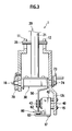
- Fig. 3 is a sectional view showing an assembled state of the shift lever device.
- the shift lever device 1 of the embodiment includes a first casing 11 and second casing 12 in pairs, as shown in Fig. 3. To the casings 11, 12 in pairs, there are attached a shift lever 20, a torque sensor 30 as a torque detecting unit, an actuator 40 as an assist-force imparting unit 40, a transmission plate 50 and a check mechanism 60.
- the torque sensor 30 is formed by a structure known in the prior art torque detecting unit.
- the first casing 11 and the second casing 12 are assembled to each other through fixing bolts 13.
- the shift lever 20 is pivotally operated by an operator (driver of vehicle) in order to change an operating range position in an automatic transmission (not shown) of a vehicle (also not shown).
- the operating range position can be changed to any one of respective operating range positions: "P" (parking range) position; “R” (reverse range) position; “N” (neutral range) position; “D” (drive range) position; “2" (second range) position; and “L” (low range) position.
- the shift lever 20 includes a shift rod 22 having its top end attached to an operating knob 21, a cylindrical lever body 23 having the shift rod 22 inserted thereinto, and an L-shaped lever base 24 attached to a lower end of the lever body 23.
- the shift rod 22 is always urged by a coil spring 26 inserted into the lever body 23, upwardly.
- a lock pin 25 is arranged to penetrate the lever body 23 and the shift rod 22 inserted into the lever body 23. Moving in operating holes 11a, 12a formed in upper parts of the first casing 11 and the second casing 12 respectively, the lock pin 25 operates to allow the shift rod 22 to come to a standstill in the above-mentioned range positions.
- the transmission plate 50 is attached to the lever base 24.
- the torque sensor 30 is carried by the transmission plate 50 and the lever base 24.
- the lever base 24 is provided, on its end face, with a rectangular recessed groove 24a. While, the transmission plate 50 is provided, on its top end, with a rectangular projection 50a. In engagement between the lever base 24 and the transmission plate 50, the rectangular projection 50 is fitted into the recessed groove 24a while remaining a designated gap.
- a lateral surface 24b is defined so as to oppose the transmission plate 50.
- the torque sensor 30 is supported, on both sides thereof, by the lateral surface 24b of the lever base 24 and the transmission plate 50.
- the torque sensor 30 has a supporting part 31 provided, on its one side, with a first shaft 31a and also provided, on the other side, with a second shaft 31b.
- the first shaft 31a is coaxial with the second shaft 31b.
- a torque detecting part 33 is interposed between the first shaft 31a and the second shaft 31b.
- the torque detecting part 33 is adapted so as to detect a torsional torque generated between the first shaft 31a and the second shaft 31b.
- both of the first shaft 31a and the second shaft 31b are together shaped to have substantially-oval cross sections each obtained as if cutting a round bar by two parallel planes partially.
- the lateral surface 24b of the lever base 24 and the transmission plate 50 have shaft holes 24c, 50c formed for engagement with the shafts 31a, 31b, respectively. Since the first and second shafts 31a, 31b are inserted into the shaft holes 24c, 50c for engagement, the torque sensor 30 is supported by the lever base 24 and the transmission plate 50.
- the transmission plate 50 is attached to the second shaft 31b of the supporting part 31 in the torque sensor 30 so as to rotate together with the second shaft 31b integrally.
- the first shaft 31a and the second shaft 31b are provided, at their respective leading ends, with axle parts 35a, 35b having circular cross-sections, respectively.
- the axle parts 35a, 35b are rotatably supported by the first casing 11 and the second casing 12 through bushes 19, 19, respectively.
- the first shaft 31a and the second shaft 31b of the torque sensor 30 penetrate the first casing 11 and the second casing 12 and project out of these casings 11, 12, respectively.
- a potentiometer 70 as a position-detecting sensor is attached to an end of the first shaft 31a projecting from the first casing 11.
- a select lever 73 is connected to the second shaft 31b projecting from the second casing 12 so as to rotate together with the second shaft 31b integrally. This connection between the second shaft 31b and the select lever 73 is completed since the second shaft 31b penetrates the select lever 73 and allows its penetrating end to thread-engage with a nut 74.
- the select lever 73 is connected to an in-vehicle automatic transmission (not shown).
- the potentiometer 70 is fixed on an outer surface of the first casing 11 through screws and also provided with a noncircular through-hole 71 that the first shaft 31a of the torque sensor 70 penetrates.
- a push nut 16 is attached to the circular axle part 35a forming a penetrating end of the first shaft 31a penetrating the through-hole 71, preventing the potentiometer 70 from dropping off the first shaft 31a.
- the potentiometer 70 With a rotation of the first shaft 31a of the torque sensor 30, the potentiometer 70 detects a pivot direction of the shift lever 20 and its assist position, allowing a detection of both rotating direction (normal/reverse rotation) and assist position of the actuator 40. In this way, owing to the provision of the potentiometer 70 on the supporting part 31 of the torque sensor 30, it is possible to detect both of the pivot direction and the assist position of the shift lever 20 with high accuracy.
- a transmitting part 51 is formed to extend downwardly of the lever base 24.
- the transmitting part 51 comprises a window part 51a at a substantially-central part of the part 51, a pair of arm parts 51b, 51b on both sides of the window part 51a, and a bridge part 51c bridging between respective lower ends of the arm parts 51b.
- the actuator 40 is interposed between the transmitting part 51 and the second casing 12.
- the actuator 40 is attached to a holder part 12c hanging from the lower end of the second casing 12 and also fixed on it by means of screws 15, 15 screwed into the holder part 12c. With this fixation, the actuator 40 is interposed between the second casing 12 and the transmission plate 50.
- the actuator 40 is formed by an electric motor 41 and a reduction-gear housing 42 assembled in alignment with the motor 41.
- the reduction-gear housing 42 is provided, on its outer surface, with a pinion gear 43.
- the pinion gear 43 is associated with an output shaft (not shown) of the electric motor 41 through reduction gears in the reduction-gear housing 42.
- the pinion gear 43 and the output shaft of the electric motor 41 are adapted so as to mutually transmit a rotating force to each other through the reduction gears.
- the pinion gear 43 of the actuator 40 is inserted into the window part 51a of the transmission plate 50.
- a transmission gear part 55 is formed in mesh with the pinion gear 55.
- the actuator 40 is connected to the shift lever 20 through the transmission plate 50. It is noted that if a load on the shift lever 20 is increased, then a torque detected by the torque sensor 30 also increases. Making use of this fact, in such a case, the actuator 40 operates to increase impressed voltage on the electric motor 41 corresponding to the so-increased torque to impart a rotating force of the electric motor 41 as an assist force to an operator' s manually-operating force against the shift lever 20.
- the rotating speed of the electric motor 41 is decelerated in one speed by the transmission gear part 55. Therefore, it is possible to miniaturize the electric motor 41 that much.
- the transmission plate 50 is also provided, on its lower surface opposing the transmission gear part 55, with a concavo-convex part 61 as a constituent of a check mechanism 60.
- the check mechanism 60 comprises the concavo-convex part 61 and a check roller 62.
- a pair of supporting parts 63a, 63a are formed by bending opposing free-end portions of an attachment arm 63 in the form of a plate spring upwardly.
- the check roller 62 is rotatably fitted to the attachment arm 63 since both ends of the roller 62 are inserted and held between the supporting parts 63a, 63a.
- the attachment arm 63 in the form of a plate spring is attached to the reduction gear housing 42 through a screw 17, so that the check roller 62 is elastically pressed on the concavo-convex part 61 of the bridge part 51c.
- the check roller 62 is engaged with the concavo-convex part 61 with pressure.
- the concavo-convex part 61 is formed so as to correspond to respective operating range positions occupied by the shift lever 20.
- the check roller 62 rotates in pressure-contact with the concavo-convex part 61.
- the check roller 62 moves from a concave part of the concavo-convex part 61 to its convex part or from a convex part of the concavo-convex part 61 to its concave part.
- a contact pressure on the concavo-convex part 61 changes.
- this change in the pressure of the check roller 62 is transmitted to the shift lever 20 through the transmission plate 50. In this way, it becomes possible to afford moderation to an operator's feeling of manipulating the shift lever 20 in the course of changing the operating range position.
- the lever base 24 rotates together with the shift lever 20. Then, a pivotal movement of the shift lever 20 is inputted to the potentiometer 70 to detect both pivot direction and pivot position of the shift lever 20. Due to the detection of these parameters, both assistant rotating direction and assist position by the actuator 40 are determined.
- the torque sensor 30 twists since the rectangular projection 50a in engagement with the recessed groove 24a moves in the gap remained in the recessed groove 24a. Thus, an operator's operating force applied on the shift lever 20 can be detected due to a torsional torque about the torque sensor 30.
- the operating range position in the automatic transmission (not shown) connected to the select lever 73 is changed.
- the attachment arm 63 bends and the check roller 62 moves from one concave part in the concavo-convex part 61 to the neighboring convex part while climbing over one convex part interposed between these concave parts. With this movement, the operator is informed of a situation where the operating range position in the automatic transmission has changed over to the other range position.
- the torque sensor 30 is assembled so that the supporting part 31 bridges between the lever base 24 and the transmission plate 50.
- the supporting part 31 of the torque sensor 30 is positioned in a pivot part of the shift lever 20 so as to double as its pivot shaft. That is, as a pivot shaft exclusive to the shift lever 20 becomes dispensable, the number of components is reduced to allow both weight-saving and miniaturization of the shift lever device.
- the transmission plate 50 rotated by the pinion gear 43 of the actuator 40 is attached to the supporting part 31 of the torque sensor 30 so as to rotate together with the part 31 integrally. Accordingly, it is possible to transmit the rotating force of the actuator 40 to the shift lever 20 directly. As a result, a long transmission cable in prior art becomes dispensable.
- As the check roller 62 and the concavo-convex part 61 in the check mechanism 60 are arranged so as to press the transmission plate 50, there is no possibility that it rattles during the operation of the shift lever device. For these reasons, it becomes possible to prevent occurrence of time-lag and delay in assistance to an operator's operating the shift lever. In addition, owing to the direct transmission of the rotating force, it is dispensable to both machine and assemble components for transmission with high accuracy.
- the check roller 62 engages with the concavo-convex part 61 of the transmission plate 50 while being in pressure-contact with the part 61 due to spring force, it is possible to prevent the transmission plate 50 from rattling during its rotating and swinging.
- the transmission plate 50 is formed with the transmission gear part 55 meshing with the pinion gear 43 of the actuator 40, the rotating force can be transmitted to the actuator 40 with a simple structure having the reduced number of components.
- the pivot direction of the shift lever 20 and the assist position are detected by the potentiometer 70. Nevertheless, such a potentiometer could be removed so long as these parameters can be detected by the torque sensor 30. Then, the number of components is reduced, so that the shift lever device can be simplified in structure and also assembled with ease.
Landscapes
- Engineering & Computer Science (AREA)
- General Engineering & Computer Science (AREA)
- Mechanical Engineering (AREA)
- Gear-Shifting Mechanisms (AREA)
- Arrangement Or Mounting Of Control Devices For Change-Speed Gearing (AREA)
Applications Claiming Priority (1)
| Application Number | Priority Date | Filing Date | Title |
|---|---|---|---|
| JP2005046215A JP2006234016A (ja) | 2005-02-22 | 2005-02-22 | シフトレバー装置 |
Publications (2)
| Publication Number | Publication Date |
|---|---|
| EP1693603A2 true EP1693603A2 (de) | 2006-08-23 |
| EP1693603A3 EP1693603A3 (de) | 2007-07-11 |
Family
ID=36190677
Family Applications (1)
| Application Number | Title | Priority Date | Filing Date |
|---|---|---|---|
| EP06003446A Withdrawn EP1693603A3 (de) | 2005-02-22 | 2006-02-20 | Schalthebelvorrichtung für Fahrzeug |
Country Status (3)
| Country | Link |
|---|---|
| US (1) | US20060185461A1 (de) |
| EP (1) | EP1693603A3 (de) |
| JP (1) | JP2006234016A (de) |
Families Citing this family (5)
| Publication number | Priority date | Publication date | Assignee | Title |
|---|---|---|---|---|
| JP2004203088A (ja) * | 2002-12-24 | 2004-07-22 | Calsonic Kansei Corp | 車両用自動変速装置 |
| ES2357411T3 (es) * | 2005-12-23 | 2011-04-26 | Innovius B.V. | Dispositivo de cambio de engranaje para aplicaciones motorizadas. |
| JP2016222234A (ja) * | 2015-05-29 | 2016-12-28 | 富士機工株式会社 | シフトレバー装置 |
| US10012307B2 (en) * | 2016-02-25 | 2018-07-03 | Fca Us Llc | Automatic transmission shifter with speed sensitive damping |
| DE102016119842B3 (de) * | 2016-10-18 | 2018-02-22 | Preh Gmbh | Betriebsarten-Wähleinrichtung für ein Fahrzeuggetriebe mit Schlittenmechanik |
Family Cites Families (8)
| Publication number | Priority date | Publication date | Assignee | Title |
|---|---|---|---|---|
| JP2898045B2 (ja) * | 1990-03-01 | 1999-05-31 | マツダ株式会社 | 車両用自動変速機の操作装置 |
| US6209408B1 (en) * | 1997-07-16 | 2001-04-03 | Grand Haven Stamped Products | Electrical sensing system for a vehicle shifter |
| EP1119719A4 (de) * | 1999-08-06 | 2006-08-23 | Stoneridge Control Devices Inc | Fahrbereichswähleinrichtung |
| US6289756B1 (en) * | 2000-01-21 | 2001-09-18 | Kelsey-Hayes Co. | Electronic shifter assembly with positioning mechanism to aid in setting shift lever to desired gear setting |
| US6658960B2 (en) * | 2001-09-21 | 2003-12-09 | American Electronic Components, Inc. | Transmission shift position sensor |
| JP2004203088A (ja) * | 2002-12-24 | 2004-07-22 | Calsonic Kansei Corp | 車両用自動変速装置 |
| DE602004001880T2 (de) * | 2003-01-07 | 2007-04-05 | Calsonic Kansei Corp. | Wählhebel für Automatikgetriebe |
| US7237450B2 (en) * | 2003-02-03 | 2007-07-03 | Calsonic Kansei Corporation | Vehicular automatic power transmission operating device |
-
2005
- 2005-02-22 JP JP2005046215A patent/JP2006234016A/ja active Pending
-
2006
- 2006-02-20 EP EP06003446A patent/EP1693603A3/de not_active Withdrawn
- 2006-02-21 US US11/358,319 patent/US20060185461A1/en not_active Abandoned
Non-Patent Citations (1)
| Title |
|---|
| None |
Also Published As
| Publication number | Publication date |
|---|---|
| JP2006234016A (ja) | 2006-09-07 |
| US20060185461A1 (en) | 2006-08-24 |
| EP1693603A3 (de) | 2007-07-11 |
Similar Documents
| Publication | Publication Date | Title |
|---|---|---|
| CN102834652B (zh) | 自动变速器的换档范围切换装置 | |
| US20070137397A1 (en) | Adjustable pedal system | |
| US20100212992A1 (en) | Transmission control apparatus for saddle-ride type vehicle | |
| JP2000168593A (ja) | 電気パワ―ステアリング装置 | |
| CN111824237A (zh) | 转向装置 | |
| EP1541903A1 (de) | Gangschaltvorrichtung | |
| EP1693603A2 (de) | Schalthebelvorrichtung für Fahrzeug | |
| JP2004203088A (ja) | 車両用自動変速装置 | |
| US20040018907A1 (en) | Shift range changeover mechanism | |
| KR100604441B1 (ko) | 자동변속기용 햅틱 변속 장치 | |
| US6796201B2 (en) | Input device provided with manipulating member that slides | |
| JP2003028293A (ja) | 車両用変速制御装置 | |
| JP2003185013A (ja) | 車両用変速制御装置 | |
| EP1528296A1 (de) | Positionwahleinrichtung für ein automatisches Getriebe. | |
| TWI826450B (zh) | 轉向裝置 | |
| JP2004239291A (ja) | 車両用自動変速装置 | |
| US20090100954A1 (en) | Control unit for automatic transmission | |
| EP1591697A2 (de) | Positionswahleinrichtung für ein automatisches Getriebe | |
| KR20190063348A (ko) | 차량용 변속조작 장치 | |
| EP1549539A2 (de) | Rückkoppelungsvorrichtung für einen elektronisch gesteuerten, elektromagnetischen stellantrieb eines kraftfahrzeugs | |
| JP2009012499A (ja) | 車両用変速機のマニュアルプレート構造 | |
| JP4430980B2 (ja) | 力覚付与型入力装置 | |
| JP2006231985A (ja) | シフトレバー装置 | |
| EP4455516A1 (de) | Arbeitsfahrzeug | |
| JP2001027318A (ja) | 変速機シフト操作装置 |
Legal Events
| Date | Code | Title | Description |
|---|---|---|---|
| PUAI | Public reference made under article 153(3) epc to a published international application that has entered the european phase |
Free format text: ORIGINAL CODE: 0009012 |
|
| 17P | Request for examination filed |
Effective date: 20060221 |
|
| AK | Designated contracting states |
Kind code of ref document: A2 Designated state(s): AT BE BG CH CY CZ DE DK EE ES FI FR GB GR HU IE IS IT LI LT LU LV MC NL PL PT RO SE SI SK TR |
|
| AX | Request for extension of the european patent |
Extension state: AL BA HR MK YU |
|
| PUAL | Search report despatched |
Free format text: ORIGINAL CODE: 0009013 |
|
| AK | Designated contracting states |
Kind code of ref document: A3 Designated state(s): AT BE BG CH CY CZ DE DK EE ES FI FR GB GR HU IE IS IT LI LT LU LV MC NL PL PT RO SE SI SK TR |
|
| AX | Request for extension of the european patent |
Extension state: AL BA HR MK YU |
|
| AKX | Designation fees paid |
Designated state(s): DE FR |
|
| STAA | Information on the status of an ep patent application or granted ep patent |
Free format text: STATUS: THE APPLICATION IS DEEMED TO BE WITHDRAWN |
|
| 18D | Application deemed to be withdrawn |
Effective date: 20080112 |