EP1693647B1 - Système pour la détermination par sections d'itinéraire - Google Patents
Système pour la détermination par sections d'itinéraire Download PDFInfo
- Publication number
- EP1693647B1 EP1693647B1 EP20060100134 EP06100134A EP1693647B1 EP 1693647 B1 EP1693647 B1 EP 1693647B1 EP 20060100134 EP20060100134 EP 20060100134 EP 06100134 A EP06100134 A EP 06100134A EP 1693647 B1 EP1693647 B1 EP 1693647B1
- Authority
- EP
- European Patent Office
- Prior art keywords
- route
- planning parameter
- destination
- region
- starting point
- Prior art date
- Legal status (The legal status is an assumption and is not a legal conclusion. Google has not performed a legal analysis and makes no representation as to the accuracy of the status listed.)
- Expired - Lifetime
Links
Images

Classifications
-
- G—PHYSICS
- G01—MEASURING; TESTING
- G01C—MEASURING DISTANCES, LEVELS OR BEARINGS; SURVEYING; NAVIGATION; GYROSCOPIC INSTRUMENTS; PHOTOGRAMMETRY OR VIDEOGRAMMETRY
- G01C21/00—Navigation; Navigational instruments not provided for in groups G01C1/00 - G01C19/00
- G01C21/26—Navigation; Navigational instruments not provided for in groups G01C1/00 - G01C19/00 specially adapted for navigation in a road network
- G01C21/34—Route searching; Route guidance
- G01C21/3446—Details of route searching algorithms, e.g. Dijkstra, A*, arc-flags or using precalculated routes
Definitions
- the invention relates to a system for determining a route with a computing unit for calculating the route within a road network from a starting point to a destination point, an input unit connected to the arithmetic unit, via which at least one planning parameter can be entered, which of the arithmetic unit during the calculation of the route is considered, as well as a memory in which the road network is stored digitally.
- a system for determining a route between a starting point and a destination point is used today in various application devices, for example in navigation devices of motor vehicles or maritime vehicles, in portable devices, such as PDAs or mobile radio devices, or even in stationary computer devices.
- the calculated route may be intended for a driver or a pedestrian.
- Object of the present invention is therefore to provide a system of the type described above, with which this problem is resolved.
- the present invention is based on the finding that the mentioned problem of unfavorable route guidance near the destination is due to the mode of operation of today's route planning method.
- This mode of operation is generally influenced by the specification of one or more planning parameters in today's systems. For example, a user may request the planning of the fastest or the shortest route or classify certain road classes as preferred or undesirable.
- the route planning algorithm then started by the system for determining a route searches in a digital road network for a route that fulfills the criteria specified by the planning parameters.
- the roads of the digital road network are generally associated with individual road classes, so for example minor roads, main roads, highways and highways. For example, if the user requests calculation of the fastest route, the route planning algorithm attempts to move within the higher street classes as much as possible.
- the disadvantage of the hitherto lacking possibility of a specific influencing of the operation of the route planning algorithm in the vicinity of a destination point or an intermediate destination is now remedied by means of the invention in that via the input unit of the route determination system at least two route areas can be predetermined and each of the route areas at least one planning parameter can be assigned.
- the arithmetic unit then calculates a route that is composed of at least two route sections, wherein each route section is assigned in each case to a route area and lies with its predominant path length within the assigned route area.
- the arithmetic unit in each case takes into account the planning parameters associated with the assigned route area.
- each predetermined route area is assigned a route section during route planning, i. E.
- the same number of route sections are created.
- Each route section lies with its predominant, i. more than half the path length within the assigned route area.
- a first distance from the starting point and / or a second distance from the destination point can be predetermined via the input unit, the radius of a circular route area being determined by each distance.
- the specification of the distance from the points can be done as a text input or graphically via mouse
- at least one lying between the starting point and the destination point, neither the start nor the destination point enclosing route area can be determined via the input unit.
- this route region may also be in the form of a circle or in the form of a width extension, for example as at right angles to the connecting line of start and end point lying corridor, are given.
- Additional route areas may be defined by providing another distance from the circles around the start and end points, the further distance determining the outer radius of an annular route area surrounding the start or end point during the first or second distance determines the inner radius of the circular route area.
- the definition of circular rings around the inner circles around the start and end point can be extended to any number. Center points of the resulting circular rings are always the start and / or the target point and the inner radius of the circular rings is determined in each case by the next smallest distance to the current distance. Thus, any number of annular route sections can be defined between the start and end point.
- a route area can be specified by defining an intermediate point via the input unit, which forms the boundary point between a circular or annular route area around the starting point and a circular or annular route area around the destination point , In this way, adjoining route areas can be predetermined, so that the entire spatial extent lying between the start and end points can be divided exactly into route areas.
- the arithmetic unit first calculates a first route on the basis of a planning parameter valid for the entire route and outputs it on an output unit, for example in the form of a graphical representation or as textual route guidance information. Based on the calculated route, the user can decide whether to have a more detailed influence on the operation of the Route planning algorithm wishes. In this case, he then defines the at least two route areas and the respectively associated planning parameters, after which the arithmetic unit calculates a second route consisting of the at least two route sections.
- This iterative approach has the advantage that the user can get an initial overview before making more detailed presets.
- the at least one planning parameter in one embodiment is at least one numerical value of a reference variable that should not be exceeded or not undershot. Accordingly, either a numerical value is defined as an upper or a lower limit, or two numerical values are specified for defining a range of values by means of upper and lower limits.
- the time duration required for covering the route section or the path length of the route section may be considered as reference variables.
- a road class can also be used as the planning parameter, it being specified either that the route section should preferably run along this road class or that the route section should preferably not run along the road class.
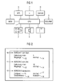
- FIG. 1 a system for determining a route for a motor vehicle is shown, consisting of a computing unit 1 and an input unit 2 and a memory 5, which are each connected to the arithmetic unit 1.
- the input unit 2 consists of control buttons.
- a pointer operating device such as a mouse or a rotary pushbutton may be present.
- a digital road map is stored, which maps the road network in which the route between a starting point and a destination point is to be calculated.
- the system for determining a route is part of a navigation system arranged in the motor vehicle.
- the navigation system further includes a satellite-based position detection unit 6, a speed sensor 7, a yaw rate sensor 8, a traffic information receiver 9 and a graphical output unit 3 and an acoustic output unit 4.
- the navigation system operates in the known manner, that is, the arithmetic unit 1 compares the from the route determining system determined route with the actually covered route and generates driving instructions that are output to assist the pursuit of the planned route to the driver. Change the traffic conditions, a new route is planned.
- a user can define route areas and enter assigned planning parameters that are taken into account during the determination of the route.
- FIG. 2 is a text output showing the result of such user input.
- a total of three route areas have been defined.
- the first route area 10 is set from the starting point of the route to be planned, the second route area 11 from the destination point, and the third route area 12 is defined as the area between the first and second route areas.
- the spatial extent of the route areas 10 and 11 and is determined by means of a respectively associated distance from the start or destination point. In this example, the distance describes in each case a circle around the starting point SP or the target point ZP, as in FIG FIG. 3 is shown.
- the first route area 10 has a circle radius of 5 km and the second route area 11 has a circle radius of 10 km.
- the third route region 12 between the first and second route regions 10 and 11 is determined by two straight lines 19 and 20, each of which runs perpendicular to the connecting straight line 21 of the starting point SP with the destination point ZP.
- the user For each route area 10, 11 and 12, the user has defined planning parameters for associated reference quantities.
- the type of reference quantities were determined beforehand via the selection menu.
- FIG. 2 It can be seen that the path length 13 has been selected as the reference variable for the first and second route regions 10 and 11 and it has been determined as associated planning parameter 14 that this path length should be minimal.
- a route section is to be planned, for the duration of which a minimum time duration is required. This is defined by the reference value 15 and the planning parameter 17. This route section should furthermore preferably run on highways, which is determined by the reference variable 16 and the planning parameter 18.
- the route planned according to these specifications is FIG. 3 refer to. Namely, the route runs along the first route section 22, the second route section 24 and the third route section 23, which are each shown as a solid line and lie with their predominant path length in the associated route areas 10, 11 and 12 respectively.
- route section 24 runs completely along a highway, which can be seen on the wider line, while the route sections 22 and 23 each lead along a main road branching off from the highway. In the event that the user did not make the division into the route areas 10, 11 and 12 and required a minimum amount of time for the entire route, a route would have been calculated along the streets shown broken.
- the system for determining a route would then have proposed to enter the highway via the road 25, since the assumed travel time along the road 25 and the subsequent motorway section to the junction of the route section 22 is less than along the route section 22.
- the user will see this detour but not necessarily as meaningful, since it first moves away from its actual destination.
- the detour he actually only takes into account if there is a clear time difference. Since this is not to be expected in the case of the constellation shown here, he will find the route proposed as a result of the route calculation in sections more favorable.
- the situation in the target area is similar to the destination point ZP.
- the system would recommend a later motorway exit and the use of the road 26 according to the assumed travel time. This in turn leads to an extension of the route, which is hardly accepted by the user.
- the system according to the invention for determining a route it is thus possible to carry out a route planning which leads to results which better correspond to the human perception of a meaningful route course.
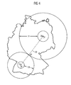
- FIG. 4 alternative possibilities for determining the spatial extent of route areas can be seen.
- the user uses a pointer operator for input in this example and traces his inputs graphically on the output unit 3.
- a first step he selects around the starting point SP by dragging a mouse pointer a first circle radius corresponding to a first distance from the starting point SP.
- the route area 27 is defined as the interior of the resulting circle.
- the user specifies a second distance for the destination point ZP, from which the circular route area 28 results. Then, starting from the starting point SP, he selects a third distance which reaches to the point GP, the point GP not yet being displayed during the input process.
- the circle radius passing through GP describes the outer boundary of a circle whose inner boundary is defined by the circle of the route area 27.
- the area of this circle defines the route area 29. Now the user selects, for example via a menu, the input option of an intermediate point.
- a connecting straight line 30 between the starting point SP and the target point ZP is superimposed and a displaceable intermediate point GP is displayed on this straight line 30.
- the user now places this intermediate point GP on the outer circle of the route area 29 by means of the mouse pointer, whereby the boundary point between the route area 29 and a route area 30 originating at the destination point ZP is determined.
- the route region 31 is in turn a circular ring, the outer boundary of which runs through GP and whose inner boundary is defined by the circle of the route region 28. For the four resulting route areas 27, 28, 29 and 31, the user can set planning parameters in a next step.
Landscapes
- Engineering & Computer Science (AREA)
- Radar, Positioning & Navigation (AREA)
- Remote Sensing (AREA)
- Automation & Control Theory (AREA)
- Physics & Mathematics (AREA)
- General Physics & Mathematics (AREA)
- Navigation (AREA)
Claims (13)
- Système destiné à déterminer un itinéraire et comportant une unité de calcul (1) pour le calcul de l'itinéraire à l'intérieur d'un réseau de routes entre un point de départ (SP) et un point de destination (ZP), une unité de saisie (2), reliée à l'unité de calcul (1) et par l'intermédiaire de laquelle il est possible de saisir au moins un paramètre de planification dont l'unité de calcul (1) tient compte lors du calcul de l'itinéraire, ainsi qu'une mémoire (5), dans laquelle le réseau de routes est stocké sous forme numérique,
caractérisé par le fait que
au moins deux zones (10, 11, 12) pour l'itinéraire peuvent être définies au préalable par l'intermédiaire de l'unité de saisie (2), qu'il est possible d'attribuer au moins un paramètre de planification (14, 17, 18) à chacune des zones (10, 11, 12) pour l'itinéraire et que l'unité de calcul (1) calcule un itinéraire qui se compose de au moins deux sections d'itinéraire (22, 23, 24), chaque section d'itinéraire (22, 23, 24) correspondant à une zone (10, 11, 12) pour l'itinéraire et se trouvant, en même temps, sur la plus grande partie de sa longueur, à l'intérieur de la zone (10, 11, 12) pour l'itinéraire correspondante et l'unité de calcul (1) calculant chaque section d'itinéraire (22, 23, 24) en tenant compte du au moins un paramètre de planification (14, 17, 18) attribué à la zone (10, 11, 12) pour l'itinéraire correspondante. - Système selon la revendication 1, caractérisé par le fait qu'il est possible de prescrire, par l'intermédiaire de l'unité de saisie (2), une première distance du point de départ (SP) et/ou une deuxième distance du point de destination (ZP), chaque distance définissant le rayon d'une zone circulaire (10, 11, 27, 28) pour l'itinéraire se trouvant autour du point de départ (SP) et/ou du point de destination (ZP).
- Système selon l'une des revendications précédentes, caractérisé par le fait qu'il est possible de prescrire, par l'intermédiaire de l'unité de saisie (2), au moins une zone (12, 29, 31) pour l'itinéraire se trouvant entre le point de départ (SP) et le point de destination (ZP).
- Système selon l'une des revendications 2 ou 3, caractérisé par le fait qu'il est possible de prescrire au moins une autre distance supplémentaire, cette autre distance supplémentaire définissant le rayon extérieur d'une zone annulaire (29, 31) pour l'itinéraire se trouvant autour du point de départ (SP) ou du point de destination (ZP), alors que la première ou la deuxième distance définissent le rayon intérieur (27, 28) de la zone annulaire (29, 31) pour l'itinéraire.
- Système selon l'une des revendications précédentes 2 à 4, caractérisé par le fait qu'il est possible de prescrire, par l'intermédiaire de l'unité de saisie (2), un point intermédiaire (GP) qui représente la limite entre une zone circulaire ou, respectivement, annulaire (29) pour l'itinéraire se trouvant autour du point de départ (SP) et une zone circulaire ou, respectivement, annulaire (31) pour l'itinéraire se trouvant autour du point de destination (ZP).
- Système selon l'une des revendications précédentes, caractérisé par le fait qu'il y a une unité graphique de sortie (3) reliée à l'unité de calcul (1), que l'unité de calcul (1) calcule un premier itinéraire à l'aide d'un paramètre de planification valable pour l'ensemble de l'itinéraire et édite cet itinéraire sur l'unité de sortie (3) et que, ensuite, l'unité de calcul (1) calcule, une fois que les au moins deux zones (10, 11, 12) pour l'itinéraire et le au moins un paramètre de planification (14, 17, 18) correspondant à chaque zone pour l'itinéraire ont été fixés, un deuxième itinéraire se composant des au moins deux sections d'itinéraires (22, 23, 24).
- Système selon l'une des revendications précédentes, caractérisé par le fait que le au moins un paramètre de planification est au moins une valeur numérique d'une grandeur de référence qui ne doit être dépassée ni vers le haut, ni vers le bas.
- Système selon l'une des revendications précédentes, caractérisé par le fait que le au moins un paramètre de planification (14, 17, 18) prescrit que, lors du calcul de la section d'itinéraire ( 22, 23, 24) correspondante, un maximum ou un minimum de la grandeur de référence (13, 15) doit être atteint.
- Système selon l'une des revendications précédentes, caractérisé par le fait que la grandeur de référence (15) du au moins un paramètre de planification (17) est le temps nécessaire pour parcourir la section d'itinéraire (24).
- Système selon l'une des revendications précédentes, caractérisé par le fait que la grandeur de référence (13) du au moins un paramètre de planification (14) est la longueur de la section d'itinéraire (22, 23).
- Système selon l'une des revendications précédentes, caractérisé par le fait que le paramètre de planification (18) est une catégorie de route.
- Système selon la revendication 11, caractérisé par le fait que, avec la catégorie de route, il est prescrit que la section d'itinéraire (24) doit, d'une façon préférentielle, passer le long de cette catégorie de route.
- Système selon la revendication 11, caractérisé par le fait que, avec la catégorie de route, il est prescrit que la section d'itinéraire ne doit pas, d'une façon préférentielle, passer le long de cette catégorie de route.
Applications Claiming Priority (1)
| Application Number | Priority Date | Filing Date | Title |
|---|---|---|---|
| DE200510004635 DE102005004635A1 (de) | 2005-02-01 | 2005-02-01 | System zur abschnittsweisen Bestimmung einer Route |
Publications (2)
| Publication Number | Publication Date |
|---|---|
| EP1693647A1 EP1693647A1 (fr) | 2006-08-23 |
| EP1693647B1 true EP1693647B1 (fr) | 2009-11-04 |
Family
ID=36201489
Family Applications (1)
| Application Number | Title | Priority Date | Filing Date |
|---|---|---|---|
| EP20060100134 Expired - Lifetime EP1693647B1 (fr) | 2005-02-01 | 2006-01-06 | Système pour la détermination par sections d'itinéraire |
Country Status (2)
| Country | Link |
|---|---|
| EP (1) | EP1693647B1 (fr) |
| DE (2) | DE102005004635A1 (fr) |
Families Citing this family (2)
| Publication number | Priority date | Publication date | Assignee | Title |
|---|---|---|---|---|
| US20080208445A1 (en) * | 2007-02-28 | 2008-08-28 | Garmin Ltd. | Route shaping systems and methods |
| DE102008043268A1 (de) * | 2008-10-29 | 2010-05-06 | Robert Bosch Gmbh | Navigationsverfahren und Navigationsvorrichtung |
Family Cites Families (11)
| Publication number | Priority date | Publication date | Assignee | Title |
|---|---|---|---|---|
| US5031104A (en) * | 1988-12-05 | 1991-07-09 | Sumitomo Electric Industries, Ltd. | Adaptive in-vehicle route guidance system |
| JP2874397B2 (ja) * | 1991-03-19 | 1999-03-24 | 松下電器産業株式会社 | 経路選出装置 |
| JP2673403B2 (ja) * | 1992-06-23 | 1997-11-05 | 本田技研工業株式会社 | 経路探索装置 |
| JP3173983B2 (ja) * | 1995-12-28 | 2001-06-04 | 松下電器産業株式会社 | 経路選出方法およびシステム |
| JP3223782B2 (ja) * | 1996-02-08 | 2001-10-29 | 三菱電機株式会社 | 車両経路算出装置 |
| JP3446930B2 (ja) * | 1996-09-30 | 2003-09-16 | 松下電器産業株式会社 | 経路選出方法および経路選出装置 |
| JP3413763B2 (ja) * | 1999-04-08 | 2003-06-09 | 株式会社ケンウッド | ナビゲーション装置 |
| DE19928295A1 (de) * | 1999-06-22 | 2000-12-28 | Bosch Gmbh Robert | Verfahren und Vorrichtung zum Bestimmen einer Route von einem Ausgangsort zu einem Zielort |
| DE10029198A1 (de) * | 2000-06-19 | 2001-12-20 | Bosch Gmbh Robert | Verfahren zur Auswahl von Karteninformationen und Navigationsvorrichtung |
| DE10162359B4 (de) * | 2001-12-18 | 2012-10-31 | Robert Bosch Gmbh | Verfahren zur Bereitstellung von Routendaten für ein Navigationsgerät |
| DE10218340A1 (de) * | 2002-04-24 | 2003-11-13 | Siemens Ag | Navigationssystem und Verfahren zur Routenbestimmung |
-
2005
- 2005-02-01 DE DE200510004635 patent/DE102005004635A1/de not_active Ceased
-
2006
- 2006-01-06 EP EP20060100134 patent/EP1693647B1/fr not_active Expired - Lifetime
- 2006-01-06 DE DE200650005274 patent/DE502006005274D1/de not_active Expired - Lifetime
Also Published As
| Publication number | Publication date |
|---|---|
| DE102005004635A1 (de) | 2006-08-10 |
| EP1693647A1 (fr) | 2006-08-23 |
| DE502006005274D1 (de) | 2009-12-17 |
Similar Documents
| Publication | Publication Date | Title |
|---|---|---|
| DE102011004670B4 (de) | Strassengestaltlernvorrichtung | |
| EP1186866B1 (fr) | Dispositif de navigation | |
| EP1505555B1 (fr) | Système de navigation avec détermination d'une route de consommation optimisée | |
| DE10013675B4 (de) | Fahrzeug-Navigationssystem | |
| EP3625785B1 (fr) | Procédé pour générer une compilation de probabilités de dépassement, procédé pour faire fonctionner un dispositif de commande d'un véhicule à moteur, dispositif de compilation de probabilités de dépassement et dispositif de commande | |
| DE102005046177A1 (de) | Fahrzeugnavigationssystem | |
| DE102015208790A1 (de) | Bestimmen einer Trajektorie für ein Fahrzeug | |
| DE102007058093B4 (de) | Verfahren und Vorrichtung zum Ermitteln einer Routenempfehlung aus einer Mehrzahl von Wegstrecken | |
| DE102015206263A1 (de) | Anwendungsvorhersage für kontextbezogene schnittstellen | |
| DE102017208931A1 (de) | Verfahren zum Unterstützen eines Benutzers eines Kraftfahrzeugs bei einer Fahrt mit dem Kraftfahrzeug, Navigationseinrichtung und Kraftfahrzeug | |
| EP2910445B1 (fr) | Procédé d'assistance d'un conducteur pour passer dans une voie de circulation rétrécie et système d'assistance du conducteur | |
| EP1947421A1 (fr) | Procédé d'émissions de directives pour tourner et dispositif de navigation | |
| DE102011118336A1 (de) | Unterstützen eines Fahrers eines Kraftfahrzeugs beim Planen eines Überholvorgangs mittels einer digitalen Karte | |
| EP1357359B1 (fr) | Dispositif et méthode pour guidage routier | |
| EP1430273A1 (fr) | Procede de calcul automatique d'itineraires optimaux | |
| EP2423643B1 (fr) | Technique de manipulation de routes basée sur un écran | |
| EP1693647B1 (fr) | Système pour la détermination par sections d'itinéraire | |
| DE102014100569A1 (de) | Navigationsverfahren und Navigationssystem | |
| EP2881298B1 (fr) | Procédé d'influence prévisionnelle de la vitesse d'un véhicule automobile | |
| EP2201552A1 (fr) | Appareil de navigation pour véhicules automobiles, et procédé de calcul et d'édition d'au moins un itinéraire de délestage en cas de bouchon | |
| DE102012201156B4 (de) | Verfahren, Datenverarbeitungsvorrichtung und Computerprogramm zum Bereitstellen von einer Geschwindigkeitswarnungsinformation für ein Navigationsgerät | |
| WO2009074370A1 (fr) | Procédé de détermination d'un itinéraire, et dispositif correspondant | |
| DE102018118589A1 (de) | Verfahren und gerät für dynamische navigationsmodifikation | |
| DE102007052297A1 (de) | Verfahren zum Betrieb eines Navigationssystems | |
| DE102016216538A1 (de) | Verfahren zum Betreiben einer Steuervorrichtung eines Kraftfahrzeugs, Steuervorrichtung und Kraftfahrzeug |
Legal Events
| Date | Code | Title | Description |
|---|---|---|---|
| PUAI | Public reference made under article 153(3) epc to a published international application that has entered the european phase |
Free format text: ORIGINAL CODE: 0009012 |
|
| 17P | Request for examination filed |
Effective date: 20060619 |
|
| AK | Designated contracting states |
Kind code of ref document: A1 Designated state(s): AT BE BG CH CY CZ DE DK EE ES FI FR GB GR HU IE IS IT LI LT LU LV MC NL PL PT RO SE SI SK TR |
|
| AX | Request for extension of the european patent |
Extension state: AL BA HR MK YU |
|
| AKX | Designation fees paid |
Designated state(s): DE FR GB IT |
|
| RAP1 | Party data changed (applicant data changed or rights of an application transferred) |
Owner name: CONTINENTAL AUTOMOTIVE GMBH |
|
| GRAP | Despatch of communication of intention to grant a patent |
Free format text: ORIGINAL CODE: EPIDOSNIGR1 |
|
| GRAS | Grant fee paid |
Free format text: ORIGINAL CODE: EPIDOSNIGR3 |
|
| GRAA | (expected) grant |
Free format text: ORIGINAL CODE: 0009210 |
|
| AK | Designated contracting states |
Kind code of ref document: B1 Designated state(s): DE FR GB IT |
|
| REG | Reference to a national code |
Ref country code: GB Ref legal event code: FG4D Free format text: NOT ENGLISH |
|
| REF | Corresponds to: |
Ref document number: 502006005274 Country of ref document: DE Date of ref document: 20091217 Kind code of ref document: P |
|
| PLBE | No opposition filed within time limit |
Free format text: ORIGINAL CODE: 0009261 |
|
| STAA | Information on the status of an ep patent application or granted ep patent |
Free format text: STATUS: NO OPPOSITION FILED WITHIN TIME LIMIT |
|
| 26N | No opposition filed |
Effective date: 20100805 |
|
| PGFP | Annual fee paid to national office [announced via postgrant information from national office to epo] |
Ref country code: IT Payment date: 20120123 Year of fee payment: 7 |
|
| PGFP | Annual fee paid to national office [announced via postgrant information from national office to epo] |
Ref country code: GB Payment date: 20130122 Year of fee payment: 8 |
|
| GBPC | Gb: european patent ceased through non-payment of renewal fee |
Effective date: 20140106 |
|
| PG25 | Lapsed in a contracting state [announced via postgrant information from national office to epo] |
Ref country code: GB Free format text: LAPSE BECAUSE OF NON-PAYMENT OF DUE FEES Effective date: 20140106 |
|
| REG | Reference to a national code |
Ref country code: FR Ref legal event code: PLFP Year of fee payment: 11 |
|
| PG25 | Lapsed in a contracting state [announced via postgrant information from national office to epo] |
Ref country code: IT Free format text: LAPSE BECAUSE OF NON-PAYMENT OF DUE FEES Effective date: 20140106 |
|
| REG | Reference to a national code |
Ref country code: FR Ref legal event code: PLFP Year of fee payment: 12 |
|
| REG | Reference to a national code |
Ref country code: FR Ref legal event code: PLFP Year of fee payment: 13 |
|
| PGFP | Annual fee paid to national office [announced via postgrant information from national office to epo] |
Ref country code: DE Payment date: 20180131 Year of fee payment: 13 |
|
| PGFP | Annual fee paid to national office [announced via postgrant information from national office to epo] |
Ref country code: FR Payment date: 20190123 Year of fee payment: 14 |
|
| REG | Reference to a national code |
Ref country code: DE Ref legal event code: R119 Ref document number: 502006005274 Country of ref document: DE |
|
| PG25 | Lapsed in a contracting state [announced via postgrant information from national office to epo] |
Ref country code: DE Free format text: LAPSE BECAUSE OF NON-PAYMENT OF DUE FEES Effective date: 20190801 |
|
| PG25 | Lapsed in a contracting state [announced via postgrant information from national office to epo] |
Ref country code: FR Free format text: LAPSE BECAUSE OF NON-PAYMENT OF DUE FEES Effective date: 20200131 |