EP1695320B1 - Procede pour fournir des donnees sur l'etat du trafic - Google Patents
Procede pour fournir des donnees sur l'etat du trafic Download PDFInfo
- Publication number
- EP1695320B1 EP1695320B1 EP03819174A EP03819174A EP1695320B1 EP 1695320 B1 EP1695320 B1 EP 1695320B1 EP 03819174 A EP03819174 A EP 03819174A EP 03819174 A EP03819174 A EP 03819174A EP 1695320 B1 EP1695320 B1 EP 1695320B1
- Authority
- EP
- European Patent Office
- Prior art keywords
- traffic
- vehicle
- value
- influence
- speed
- Prior art date
- Legal status (The legal status is an assumption and is not a legal conclusion. Google has not performed a legal analysis and makes no representation as to the accuracy of the status listed.)
- Expired - Lifetime
Links
- 238000000034 method Methods 0.000 title claims description 39
- 238000001514 detection method Methods 0.000 claims description 33
- 230000009467 reduction Effects 0.000 claims description 5
- 238000004590 computer program Methods 0.000 claims description 4
- 238000004804 winding Methods 0.000 claims description 4
- 238000012544 monitoring process Methods 0.000 claims description 3
- 230000002411 adverse Effects 0.000 description 6
- 230000005540 biological transmission Effects 0.000 description 5
- 230000008859 change Effects 0.000 description 5
- 230000008569 process Effects 0.000 description 5
- 238000013480 data collection Methods 0.000 description 4
- 238000010586 diagram Methods 0.000 description 4
- WYTGDNHDOZPMIW-RCBQFDQVSA-N alstonine Natural products C1=CC2=C3C=CC=CC3=NC2=C2N1C[C@H]1[C@H](C)OC=C(C(=O)OC)[C@H]1C2 WYTGDNHDOZPMIW-RCBQFDQVSA-N 0.000 description 2
- 230000000694 effects Effects 0.000 description 2
- 238000012360 testing method Methods 0.000 description 2
- 230000001133 acceleration Effects 0.000 description 1
- 238000009825 accumulation Methods 0.000 description 1
- 238000004422 calculation algorithm Methods 0.000 description 1
- 238000004364 calculation method Methods 0.000 description 1
- 230000001934 delay Effects 0.000 description 1
- 230000001419 dependent effect Effects 0.000 description 1
- 238000011156 evaluation Methods 0.000 description 1
- 230000006872 improvement Effects 0.000 description 1
- 230000004048 modification Effects 0.000 description 1
- 238000012986 modification Methods 0.000 description 1
- 230000008520 organization Effects 0.000 description 1
- 238000001556 precipitation Methods 0.000 description 1
- 230000001960 triggered effect Effects 0.000 description 1
Images




Classifications
-
- G—PHYSICS
- G08—SIGNALLING
- G08G—TRAFFIC CONTROL SYSTEMS
- G08G1/00—Traffic control systems for road vehicles
- G08G1/01—Detecting movement of traffic to be counted or controlled
- G08G1/0104—Measuring and analyzing of parameters relative to traffic conditions
-
- G—PHYSICS
- G08—SIGNALLING
- G08G—TRAFFIC CONTROL SYSTEMS
- G08G1/00—Traffic control systems for road vehicles
- G08G1/20—Monitoring the location of vehicles belonging to a group, e.g. fleet of vehicles, countable or determined number of vehicles
Definitions
- the invention relates to a method for providing traffic condition data, a method for transmitting traffic condition data, a method for generating and transmitting traffic condition data, and a computer program product for use in a motor vehicle and for generating and transmitting traffic condition data according to the preamble of the independent one claim.
- FCD floating car data
- the system used consists of a GPS receiver and a GSM module. Both modules are already available in many vehicles without FCD functionality.
- the GPS receiver measures the position and the FCD methods determine travel times of the vehicle from many of these position data. These travel times are transmitted via the GSM network as pearl necklaces (individual points of the route with location coordinates and timestamps) to the traffic data center. These can draw conclusions about the traffic situation from these travel times. In this way, data collection of traffic condition data for traffic information services is performed.
- the data transmission over the GSM network is associated with considerable costs.
- FCD In order to increase the traffic situation more precisely and additionally with information about weather, road conditions and local dangers in the future, FCD will be further developed into XFCD (Extended Floating Car Data).
- XFCD uses the various existing sensors and subsystems in the vehicle, which already provide their data on central data buses in the vehicle. The evaluation of the various data during the journey can provide information on traffic conditions, obstructions, road conditions (road surface), infrastructural conditions (serpentine), local hazards, precipitation, smoothness and slipping hazards.
- a method for displaying speed variables in a vehicle is known. It is proposed to determine the current position of the vehicle via a positioning device arranged in the vehicle and to assign a position in a digital map to the position of the vehicle.
- the position of the vehicle is assigned an area, in particular a state, a country or a city area, from the position in the digital map and an indication of a current vehicle speed or a permissible maximum speed for at least one road class in the area in a physical unit which is essentially provided in the area for road traffic.
- the object of the invention is in particular a method for providing high quality traffic condition data at acceptable costs.
- An essential aspect of the method according to the invention for providing traffic status data in the context of a traffic condition detection by a motor vehicle is that it is determined in a first step, whether the vehicle is exposed to at least one traffic influence that usually or compared to a reduction of the speed of the vehicle. the normal speed without such traffic influences, in a second step a value for the respective traffic influence is set for each corresponding traffic influence, in a third step an addition of the values of the traffic influences and thus a total value for the traffic influences is formed, in a fourth step Comparison of the determined total value is made with a predetermined reference value, and in a fifth step, a lower speed threshold and / or an upper speed threshold is lowered if the determined total value is greater than or equal to the reference value.
- negative traffic influences are included in the traffic status detection according to the invention, which usually lead to the driver being able to compare the speed with the traffic. reduced in a situation where there is no negative traffic or negative traffic.
- the consideration of negative traffic influences such as risk of black ice, black ice, fog, darkness, heavy rainfall, snowfall, winding route, etc., increases the reliability of detecting a traffic condition change, such as entering into a congestion (jam entrance) or the exit from a jam when the jam is over (congestion exit), because a very reliable distinction between a reduced speed due to the mentioned traffic influences, which do not necessarily lead to a congestion, and a reduced speed due to congestion can be.
- the acceptance of the use of the method according to the invention is increased due to the increasing reliability and costs for the transmission of false traffic jams from the vehicle to a corresponding the traffic situation reconstructing and performing institution, in particular a traffic data center, saved.
- the costs are, in particular, costs for corresponding SMS messages (short message service) or costs for a different transmission.
- the inventive method allows an event-oriented or state-oriented generation of traffic status data. Traffic condition data is transmitted only when the detected traffic condition, e.g. a traffic jam, this causes.
- the inventive method allows cost-effective and even timely data collection by the vehicle for the entire road network, especially on highways, rural roads and on roads in city traffic.
- the values for the different traffic influences are at least partially different.
- the various traffic influences can be flexibly weighted with regard to their individual influence on the usual speed with which the vehicle moves over the relevant road section.
- the value for the relevant traffic influence is not set or added until the traffic influence in question has been present for a predetermined period of time uninterruptedly.
- the time duration during which the traffic influence in question is detected via a counter associated with the traffic influence in question and the count of the counter is set to "0" when the traffic influence no longer exists.
- the lower speed threshold and / or the upper speed threshold is reduced to approximately 90% of the value before the reduction if the determined total value is greater than or equal to the reference value. This has proven to be suitable in practice so far. It is understood that the percentage may be different or may be chosen differently for the two speed thresholds, if this can achieve a more reliable traffic condition detection or traffic jam detection.
- the data acquisition method according to the invention also makes possible an advantageous method for transmitting traffic condition data from a first vehicle to a second vehicle, in particular via an ad hoc network, or from a traffic data center to one or more motor vehicles, optionally modified, in particular via broadcast. Likewise, it enables an advantageous method and computer program product for use in a motor vehicle to generate and broadcast traffic condition data.
- POI stands for "Point of Interest", such as restaurants, gas stations, hospitals etc.
- Data from the digital map provides information about whether the vehicle is even on a public road or z. B. located on a large park, a rest area or gas station.
- the flow chart of the determined traffic condition scope software module 100 uses the following sequential comparisons to find indications that the vehicle is not moving in the usual way on the road.
- the comparison 101 it is checked whether the door is open, in the comparison 102 it is checked whether a POI (Point of Interest) is in the vicinity, in the comparison 103 it is checked whether a high steering activity is present, in the comparison 104 is checked whether the reverse gear or the idling of the vehicle is engaged, in the comparison 105 is checked based on the data supplied by the navigation system (not shown), whether the vehicle is off the road, in the comparison 106, it is checked whether the handbrake is engaged, in the comparison 107 is checked whether the airbag has been triggered.
- the comparison 101 it is checked whether the door is open, in the comparison 102 it is checked whether a POI (Point of Interest) is in the vicinity, in the comparison 103 it is checked whether a high steering activity is present, in the comparison 104 is checked whether the reverse gear or the idling of the vehicle is engaged, in the
- a counter 108 is increased by "1". For example, if the door is opened, the comparison 101 gives a first "yes” and the counter is set to "1". In the next second, a new comparison 101 is made, and the counter is set to "2" with the door open, and so on. If the door is closed, the result is "No", and the next second is 102. If the result is "Yes “the counter is increased by" 1 "to” 3 ". If there is no positive comparison during a run of the comparisons 101 to 107, the count of the counter is reset to "0". Each positive comparison thus increases the count of the counter 108, but only until there is a run through the comparisons 101 to 107, in which the result of the comparisons was always “no". Possibly. the counter 101 is set to "0" as indicated at 109.
- the value t1 in a comparison 110 is set to "60" in this embodiment. If the count of the counter 108 does not reach the count "60", the result of the comparison 110 is "No" and the detection of whether a jam exists is suspended, as indicated by "Detection PAUSE” 111. Is the result of Comparison 110 "Yes”, ie if one of the states of the comparisons 101 to 107 is present for more than 60 seconds, a reset of the detection whether a congestion is present or not is carried out. This is indicated by “detection RESET” 112. How the “detection RESET” is performed or what it causes will be explained later in connection with Figure 5 in more detail.
- comparisons 101 to 107 can also be run in a different order. For example, query 106 could determine whether the handbrake is engaged prior to query 101, whether a door is open.
- the known standard sensor interface (SSI) 201 provides the normal speed (normal speed in an undisturbed traffic flow) for some streets on the basis of a digital map (not shown) having this information. For all other roads is on the digital map, usually a DVD of the navigation system, recorded which street type 202 and which street category 203 belongs to the concrete road. If the normal speed to be expected is not available, the expected speed level for an undisturbed traffic flow is assigned according to the invention for all other roads using a table 204 with entries for the different "road types" and possibly for the different "road categories”.
- the table 204 has a lower speed threshold S1 and an upper speed threshold S2 (expected speed level) for the respective road type, wherein it is also possible to distinguish whether the vehicle is moving on-site or off-road on this road type (street category). If the vehicle is on a developed main road, the normal speed is z. B. according to the maximum speed, in particular about 100 km / h.
- the lower speed threshold S1 is in the table at 35 km / h
- the upper speed threshold S2 at 45 km / h is set in the table, respectively.
- the normal speed for the concrete road can also be specified on the digital map. Possibly.
- the lower speed threshold S1 is set at 35% of the normal speed and the upper speed threshold S2 is set at 45% of the normal speed.
- the lower speed threshold S1 and the upper speed threshold S2 thus orient themselves at the normal speed.
- Table 204 below gives preferred values: Road category according to SSI Inland (S1 / S2) [ km / h ] Out of town (S1 / S2) [ km / h ] 0 unspecified as previously as previously 1 highway - 46/60 2 fast road 15/25 35/45 3 regional road 15/25 30/40 4 main road 15/25 30/40 5 local road 15/25 30/40 6 connecting road 15/25 30/40 7 slow road 10/20 25/35 8 minor road 10/20 25/35 9 service road 10/20 25/35
- the speed thresholds S1 and S2 are passed to a software module for determining the boundary conditions weather and road guidance according to FIG. 3, which possibly adapts the speed thresholds to the boundary conditions.
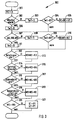
- FIG. 3 shows the flowchart of the software module 300 for determining the boundary conditions of weather and road guidance.
- step 302 it is compared whether the wiper of the vehicle wipes. If the result of the comparison 302 is "yes”, a value Tw1, which indicates the length of the windscreen wiper activity, is increased by the value "1" in step 303.
- step 304 it is compared whether the current value of Tw1 is higher than a value K1 indicating a lower time threshold. If the windscreen wiper runs longer than the lower time threshold K1, i.
- N1 M0 + N1.
- N1 is a value expressing how large the influence on the normal speed of the vehicle without adverse constraints is, and thus represents a weight for the condition "wiper wipes".
- N6 is a value that expresses how much influence is on the normal speed of the vehicle without adverse marginal conditions and thus represents a weight for the condition "temperature lower than 4 degrees Celsius and also wiper on”.
- step 320 If the result of the comparison is "No" or if N6 has been added in step 319, the process continues with step 320.
- step 320 it is checked whether the value M6 is greater than a predetermined value Mb.
- Mb is an empirical value or is determined, for example, by test drives and indicates from which value at a lower speed due to the aforementioned boundary conditions. the normal speed is calculated. If the result of the comparison 320 is "Yes", the lower speed threshold S1 and the upper speed threshold S2 are respectively reduced from the software module 200 for determining the expected speed level by multiplication by a value P1 smaller than 1. In practice, it has been found that a value P1 of about 0.9 is suitable, i. that the S1 and S2 should be reduced to about 90% of their normal value under the conditions mentioned above.
- the chain shown in FIG. 3 is again (preferably) run through approximately once per second, unless it is determined that the vehicle is outside the scope of the jam recognition according to the invention (see FIG.
- FIG. 4 shows the flow chart of a software module 400 for detecting intersection areas. Delays in the flow of traffic that occur through intersections, both light-signal-controlled and non-light-signal-controlled, are recognized as such and are filtered out during normal deceleration and subsequent intersection crossing. In this way, a crossing-free driving profile is practically emulated, thus enabling condition recognition even in intersections. For this, the SSI data "distance to the next intersection" (from the navigation system with digital map) and "speed" are used. A traffic jam in front of an intersection area is identified in the actual traffic condition recognition, FIG. 5.
- step 404 If the result of the comparison 401 is "no", ie the vehicle is not traveling in the area of an intersection, the actual speed v of the vehicle is forwarded as speed v2 in step 404 to the traffic condition recognition of FIG.
- FIG. 5 shows the flowchart of a traffic state detection software module 500 by means of a threshold method, i. to determine if there is a traffic jam or if you are free to drive.
- the inventive software module 500 allows the determination of a position indication for the traffic jam entrance and a position indication for the congestion exit.
- the basic data for the threshold value process performed by the software module 500 is the data obtained from the above four software modules and the current vehicle speed data. If the software module 100 (scopes) determines that the vehicle is not participating in the traffic flow, the traffic condition detection of FIG. 5 is suppressed. After participating in the traffic, the module data are used to modify the speed values v2 and to determine the current threshold values S1 and S2. The weather conditions, road conditions and road conditions (intersections, serpentines) are used to change the speed data. The modified speed data will be used for further calculations used.
- the threshold values are determined via the setpoint speed (software module 200). They divide the entire speed range into three parts; Speed v less than S1, v between S1 and S2 and v greater than S2.
- the modified speed data is preferably assigned to one of the three areas every second.
- the determination of the currently prevailing traffic conditions then takes place via the frequencies of the modified speed data in the individual areas.
- Traffic light and crossing areas are already taken into account by the modification of the speed data. Traffic jams in traffic lights or crossing areas are recognized in the same way as in traffic-free areas.
- the first step 501 of the flowchart of the software module 500 it is checked whether the speed v2 (possibly an intersection-adjusted speed of FIG. 4) is less than the lower speed threshold S1 (possibly modified by the boundary conditions of weather, road conditions and road guidance). If the result of the comparison 501 is "yes", which is regarded as an indication of a congestion, in step 502, starting from the count "0", it is counted up by a first counter by the value W1 (count 1 + W1). The first counter thus takes into account a low speed v2 ⁇ S1 of the vehicle. Since the flowchart is (preferably) run through every second, counting is continued every second if the comparison result remains the same.
- the state of the counter in step 502 is compared in step 503 with a value S5 (count 1> S5).
- step 504 If the result of the comparison 501 is "no", ie v2 is smaller than the lower speed threshold S1, it is checked in step 504 whether the (possibly modified) speed of the vehicle v2 is less than the upper speed threshold S2. If the result of the comparison 504 is "yes”, which is regarded as a clue for free travel or no congestion, in step 505, starting from the count "0", a second counter increments by the value W2 (count 2 + W2). The second counter thus takes into account a high speed v2> S2 of the vehicle. Since the flowchart is (preferably) run through every second, counting is continued every second if the comparison result remains the same.
- the meter reading may increase of the second counter in step 505 every second by the value "1", ie W2 is preferably "1". Of course, another value, such as "0.5”, could also be added.
- the state of the second counter in step 505 is compared with the value S8 in step 506. If the result is "yes”, the count of the first counter is reset to "0" in step 508. If the result is "no", step 517 continues.
- the first counter is then counted up in the event of congestion in step 502.
- the count of the first counter may exceed the value S5 and the result of the comparison 503 is "Yes”.
- the second counter is incremented in free travel in step 505 (count 2 + W2).
- the count of the second counter may exceed the value S8 and the result of the comparison 506 is "Yes”.
- step 513 it is checked whether the count of the second counter (count 2) has been reset to "0" for the first time in step 507. If the result is "yes”, in step 514 the location and the time at which the counter reading of the counter 1 was first greater than the value S5 in step 503 are stored (potential traffic jam entrance). Potentially because in step 509 it has yet to be shown whether there really is a traffic jam. In step 515, it is checked whether the count of the first counter (count 1) has been reset to "0" for the first time in step 508. If the result is "yes”, in step 516 the location and the time at which the counter reading of the counter 2 was first greater than the value S8 in step 506 were stored (potential congestion exit). Potentially because in step 511 it has yet to show whether there really is no traffic jam.
- step 517 it is checked in step 517 whether the absolute value of the difference between count 1 and count 2 is greater than a value S9 (
- S9
- step 504 If the speed v2 is between S1 and S2, the result of the comparison in step 504 is "No". This situation is considered an undefined state, i. It is not clear whether there is a traffic jam or no traffic jam or free travel.
- step 504 ' the count of the first counter is then increased by the value W3 and the count of the second counter also by the value W3, if necessary, every second, when the pass through the chain shown in Figure 5 takes place every second.
- W1 and W2 have the same value, W3 preferably having half the value of W1 or W2.
- the value of W1 or W2 is "1" and the value of W3 is "0.5". It will be appreciated that another weighting may be used if this results in more reliable jam detection.
- the count of the first counter (low speed) is compared in seconds with the value S6 in step 509 (count 1> S6). If the count of the first counter is greater than S6, if the result of the comparison is "yes”, in step 510 a first data set is generated which describes the state "congestion”. In step 518, it is checked whether there is a state change, i. whether the state "congestion" was preceded by the state "free". Each time the vehicle is restarted, the "free" state is set as the initial state.
- the first data record and the location and time of the (previously only potential) traffic jam entrance in step 519 for the purpose of data collection to a traffic situation reconstructing and representing institution, in particular a traffic data center, preferably a regional traffic data center , preferably by SMS, transmitted.
- step 511 it is checked whether the count of the second counter is greater than a value S7. If the result of the comparison is "yes”, a second data record is generated in step 512, which describes the state "free".
- step 520 it is checked whether there is a state change, i. whether the state "free” was preceded by the state "congestion". If the result of the comparison is "yes”, the second data set and the location and time of the (previously only potential) congestion exit in step 521 for the purpose of data collection to an organization reconstructing and representing the traffic situation, in particular a traffic data center, preferably a regional traffic data center , preferably by SMS, transmitted.
- a traffic data center preferably a regional traffic data center , preferably by SMS, transmitted.
- step 501 If the result of the comparisons in steps 518 or 520 is "no", no data transmission takes place. Rather, the method described in FIG. 5 starts again with step 501.
- step 509 If the count of the first counter (traffic jam entrance) is less than or equal to S6 in step 509, the result of the comparison 509 is "no". Then, in the next step 511, it is checked whether the count of the second counter (congestion exit or free travel) is greater than or equal to S7. If the counter reading of the second counter is greater than or equal to S7, the result of the comparison is "yes" and the institution reconstructing and representing the traffic situation is preferably once again transmitted via SMS the status "free” in step 512 for the purpose of the traffic situation survey.
- step 513 In order to be able to determine the location of the traffic jam entrance and to be able to transmit it to the traffic situation reconstructing and representing institution (not shown), after the resetting of the second counter in step 507 it is checked in step 513 whether it is the first pass or not whether this comparison 513 is performed for the first time. If the second counter has been reset to "0" for the first time in step 507, the result of the comparison 513 is "yes" and the position of the vehicle determined from the data of the navigation system at that time is stored as "congestion” in step 514.
- the position of the vehicle stored in step 514 ie, the "traffic jam entrance" to the institution reconstructing and representing the traffic situation is preferably also transmitted by SMS.
- step 515 In order to also be able to determine the location of the congestion exit and to be able to transmit to the traffic situation reconstructing and performing institution (not shown), it is checked in step 515 after the resetting of the first counter in step 508 whether it is the first pass or whether this comparison 515 is performed for the first time. If the first counter was reset to "0" for the first time in step 508, the result of the comparison 515 is "yes" and the position of the vehicle determined from the data of the navigation system at that time is stored as "congestion exit" in step 516. When transmitting the status "idle” in step 512, it is also preferred to have the position of the vehicle stored in step 516, i. the "congestion exit" to the traffic situation reconstructing and performing institution preferably transmitted via SMS.
- step 509 If the result of comparison 513 or 515 is No, or if the traffic jam entrance in step 514 or the jam exit has been stored in step 516, the comparison continues in step 509.
- a value of about 60 seconds is selected for S5 and a value of about 180 seconds for S6 and S7. It will be appreciated that values other than these practical values may be chosen if they allow a more reliable detection of jams.
Landscapes
- Chemical & Material Sciences (AREA)
- Analytical Chemistry (AREA)
- Physics & Mathematics (AREA)
- General Physics & Mathematics (AREA)
- Traffic Control Systems (AREA)
- Navigation (AREA)
Claims (10)
- Procédé pour fournir des données d'état du trafic dans le cadre d'une reconnaissance de l'état du trafic 500 par un véhicule,
caractérisé en ce que- dans une première étape 302, 307, 312, 314, 315, 318, on détermine si le véhicule est exposé à au moins une influence du trafic qui aboutit habituellement à une réduction de la vitesse du véhicule par rapport à la vitesse normale sans influence du trafic ;- dans une seconde étape, pour chaque influence du trafic, correspondante, on fixe une valeur N1, N2, N3, N4, N5, N6 pour l'influence du trafic concernée ;- dans une troisième étape, on additionne 305, 310, 313, 315, 317, 319 les valeurs des influences du trafic pour former une valeur totale des influences du trafic ;- dans une quatrième étape 320 on compare la valeur totale obtenue M6 à une valeur de référence prédéfinie Mb ; et- dans une cinquième étape 321, on réduit 321 un seuil inférieur de vitesse S1 et/ou un seuil supérieur de vitesse S2, si la valeur totale M6 est supérieure ou égale à la valeur de référence Mb. - Procédé selon la revendication 1,
caractérisé en ce que
les valeurs N1, N2, N3, N4, N5, N6, pour les différentes influences de circulation 302, 307, 312, 314, 316, 318 sont au moins en partie différentes. - Procédé selon la revendication 1 ou 2,
caractérisé en ce qu'
on fixe ou on additionne la valeur N1, N2 de l'influence du trafic concerné seulement si cette influence du trafic est ininterrompue pendant une durée prédéfinie K1, K2. - Procédé selon la revendication 3,
caractérisé en ce qu'
on a des durées K1, K2 au moins en partie différentes pour des influences de circulation différentes 303, 307. - Procédé selon l'une des revendications 3 ou 4,
caractérisé en ce que
l'on saisit la durée Tw 1, Tw2, pendant laquelle existe l'influence de circulation concernée à l'aide d'un compteur 303, 308 associé à cette influence du trafic et on met à « 0 » l'état de comptage du compteur 306, 311 lorsque l'influence du trafic disparaît. - Procédé selon l'une des revendications 1 à 5,
caractérisé en ce qu'
on détermine l'influence du trafic « pluie » en demandant l'état des essuie-glace du pare-brise 302 et/ou l'influence du trafic « chaussée glissante » en interrogeant l'état du système ASC et/ou DSC ou ABS 307, et/ou l'influence du trafic « brouillard » en interrogeant l'état des feux de brouillard 312 et/ou l'influence de circulation « trajet sinueux » 314 en surveillant l'angle de braquage et/ou l'influence du trafic luminosité en interrogeant un capteur de lumière diurne ou en interrogeant l'état des feux de croisement 316 et/ou l'influence du trafic « température extérieure » en vérifiant si la température extérieure est inférieure à 4°C et si de plus les essuie-glace de pare-brise sont en marche 318. - Procédé selon l'une des revendications précédentes,
caractérisé en ce qu'
on réduit à environ 90 % de la valeur avant réduction le seuil inférieur de vitesse S1 et/ou le seuil supérieur de vitesse S2 si la valeur totale obtenue est supérieure ou égale à la valeur de référence 320. - Procédé de transmission de données d'état du trafic d'un premier véhicule vers un second véhicule,
caractérisé en ce que
la collecte des données concernant l'état du trafic se fait à l'aide d'un procédé selon l'une des revendications de procédé précédentes. - Procédé pour générer et émettre des données d'état du trafic dans un véhicule,
caractérisé en ce que
la génération des données d'état du trafic se fait à l'aide d'un procédé selon l'une des revendications 1 à 7. - Programme d'ordinateur en tant que produit utilisé dans un véhicule pour générer et émettre des données d'état du trafic,
caractérisé en ce que
le programme d'ordinateur exécute un procédé selon l'une des revendications de procédé 1 à 7.
Applications Claiming Priority (1)
| Application Number | Priority Date | Filing Date | Title |
|---|---|---|---|
| PCT/EP2003/014644 WO2005064568A1 (fr) | 2003-12-19 | 2003-12-19 | Procede pour fournir des donnees sur l'etat du trafic |
Publications (2)
| Publication Number | Publication Date |
|---|---|
| EP1695320A1 EP1695320A1 (fr) | 2006-08-30 |
| EP1695320B1 true EP1695320B1 (fr) | 2007-10-10 |
Family
ID=34717111
Family Applications (1)
| Application Number | Title | Priority Date | Filing Date |
|---|---|---|---|
| EP03819174A Expired - Lifetime EP1695320B1 (fr) | 2003-12-19 | 2003-12-19 | Procede pour fournir des donnees sur l'etat du trafic |
Country Status (4)
| Country | Link |
|---|---|
| EP (1) | EP1695320B1 (fr) |
| DE (1) | DE50308383D1 (fr) |
| ES (1) | ES2291754T3 (fr) |
| WO (1) | WO2005064568A1 (fr) |
Cited By (2)
| Publication number | Priority date | Publication date | Assignee | Title |
|---|---|---|---|---|
| WO2013139551A1 (fr) | 2012-03-21 | 2013-09-26 | Bayerische Motoren Werke Aktiengesellschaft | Procédé et dispositif de détermination d'un état de trafic routier |
| CN106297321A (zh) * | 2016-08-29 | 2017-01-04 | 成都汉康信息产业有限公司 | 一种城市拥堵路段车流指示监测系统 |
Families Citing this family (3)
| Publication number | Priority date | Publication date | Assignee | Title |
|---|---|---|---|---|
| DE102012219850A1 (de) | 2012-10-30 | 2014-04-30 | Robert Bosch Gmbh | Datenverarbeitungseinrichtung und Verfahren für eine solche Datenverarbeitungseinrichtung |
| GB201415802D0 (en) * | 2014-09-07 | 2014-10-22 | Tomtom Int Bv | Methods and systems for identifying navigable elements affected by weather conditions |
| CN105139645A (zh) * | 2015-07-23 | 2015-12-09 | 合肥革绿信息科技有限公司 | 一种基于浮动车技术的城市区域路网运行指数评估方法 |
Family Cites Families (6)
| Publication number | Priority date | Publication date | Assignee | Title |
|---|---|---|---|---|
| DE4201142C2 (de) * | 1991-01-18 | 2001-11-29 | Mazda Motor | Fahrgeschwindigkeitsbegrenzungsvorrichtung |
| DE4205979A1 (de) * | 1992-02-27 | 1993-09-02 | Bosch Gmbh Robert | Navigationseinrichtung fuer landfahrzeuge |
| DE19725075A1 (de) * | 1997-06-13 | 1998-12-17 | Bosch Gmbh Robert | Einrichtung zur Bereitstellung von Informationen über die jeweils vorgegebene Höchstgeschwindigkeit in einem Kraftfahrzeug |
| US6246948B1 (en) * | 1998-12-10 | 2001-06-12 | Ericsson Inc. | Wireless intelligent vehicle speed control or monitoring system and method |
| DE19950156C5 (de) * | 1999-10-19 | 2010-03-04 | Robert Bosch Gmbh | Verfahren zur automatischen Anpassung der Anzeige eines Kombiinstruments |
| US6462675B1 (en) * | 2000-10-13 | 2002-10-08 | International Business Machines Corporation | Method, system, and program for auditing driver compliance to a current speed limit |
-
2003
- 2003-12-19 WO PCT/EP2003/014644 patent/WO2005064568A1/fr not_active Ceased
- 2003-12-19 DE DE50308383T patent/DE50308383D1/de not_active Expired - Lifetime
- 2003-12-19 EP EP03819174A patent/EP1695320B1/fr not_active Expired - Lifetime
- 2003-12-19 ES ES03819174T patent/ES2291754T3/es not_active Expired - Lifetime
Cited By (4)
| Publication number | Priority date | Publication date | Assignee | Title |
|---|---|---|---|---|
| WO2013139551A1 (fr) | 2012-03-21 | 2013-09-26 | Bayerische Motoren Werke Aktiengesellschaft | Procédé et dispositif de détermination d'un état de trafic routier |
| DE102012204542A1 (de) | 2012-03-21 | 2013-09-26 | Bayerische Motoren Werke Aktiengesellschaft | Verfahren und Vorrichtung zum Ermitteln eines Verkehrszustandes |
| US9460614B2 (en) | 2012-03-21 | 2016-10-04 | Bayerische Motoren Werke Aktiengesellschaft | Method and apparatus for determining traffic status |
| CN106297321A (zh) * | 2016-08-29 | 2017-01-04 | 成都汉康信息产业有限公司 | 一种城市拥堵路段车流指示监测系统 |
Also Published As
| Publication number | Publication date |
|---|---|
| ES2291754T3 (es) | 2008-03-01 |
| EP1695320A1 (fr) | 2006-08-30 |
| WO2005064568A1 (fr) | 2005-07-14 |
| DE50308383D1 (de) | 2007-11-22 |
Similar Documents
| Publication | Publication Date | Title |
|---|---|---|
| EP1695317B1 (fr) | Identification d'etat du trafic par un procede de valeurs seuils | |
| EP1695295B1 (fr) | Verification du champ d'application de donnees sur l'etat du trafic | |
| DE102015207804B4 (de) | Verfahren zum Erkennen von Parkflächen und/oder Freiflächen | |
| EP0931301B1 (fr) | Procede et dispositif pour la transmission de donnees pour l'evaluation de la situation du trafic | |
| DE112019000714T5 (de) | Glasfasererfassung zur autobahninstandhaltung | |
| WO2005064566A1 (fr) | Procede pour determiner un niveau de vitesse auquel s'attendre | |
| EP0879459A1 (fr) | Procede pour l'obtention de donnees relatives a une situation de trafic | |
| DE102011085287A1 (de) | Verfahren zur Ermittlung der Bodenbeschaffenheit | |
| DE102012201472A1 (de) | Verfahren zur Bereitstellung von Parkinformationen zu freien Parkplätzen | |
| EP3347737B1 (fr) | Procédé de détection d'une aire de stationnement d'une section de route | |
| WO2013056767A1 (fr) | Procédé pour déterminer des informations de parcours à jour sur une carte numérique | |
| WO2013091742A1 (fr) | Procédé pour générer et exploiter des informations pertinentes sur la circulation par des véhicules d'un pool de véhicules | |
| EP4150511B1 (fr) | Procédé de commande d'une surveillance d'état d'un tronçon de route d'un réseau routier faisant appel à une flotte, ainsi que système associé, véhicule automobile et dispositif serveur associé | |
| CN108711281A (zh) | 一种运用路段实际运行车速数据评价公路安全性的方法 | |
| DE102005059902A1 (de) | Verfahren zur Sensorzustandserfassung sowie Abstandsmessvorrichtung und Einparkassistenzsystem | |
| DE102010043673A1 (de) | Navigationssystem und Navigationsverfahren mit Verkehrsbeeinträchtigungs-Erkennungsfunktion | |
| EP1695314B1 (fr) | Identification de zones de croisement lors d'une identification de l'etat du trafic | |
| EP3770879B1 (fr) | Procédé, dispositif et programme informatique permettant de traiter des données au niveau d'un feu de signalisation | |
| WO2013139551A1 (fr) | Procédé et dispositif de détermination d'un état de trafic routier | |
| DE19833614B4 (de) | Verfahren zur Verkehrsqualitätserkennung und Fahrzeug als Mittel dazu | |
| DE102012009822A1 (de) | Verfahren zur Ermittlung einer Größe zur Beschreibung eines lokalenVerkehrs | |
| WO2021001460A1 (fr) | Détermination de l'état de composants de carrosserie | |
| EP1262934B1 (fr) | Méthode pour la detection de la situation du trafic routier | |
| DE102011122825B4 (de) | Vorrichtung zur Erfassung von Umfeldinformationen eines Kraftfahrzeuges | |
| EP1695320A1 (fr) | Procede pour fournir des donnees sur l'etat du trafic |
Legal Events
| Date | Code | Title | Description |
|---|---|---|---|
| PUAI | Public reference made under article 153(3) epc to a published international application that has entered the european phase |
Free format text: ORIGINAL CODE: 0009012 |
|
| 17P | Request for examination filed |
Effective date: 20060519 |
|
| AK | Designated contracting states |
Kind code of ref document: A1 Designated state(s): DE ES FR GB IT SE |
|
| 17Q | First examination report despatched |
Effective date: 20061013 |
|
| RBV | Designated contracting states (corrected) |
Designated state(s): DE ES FR GB IT SE |
|
| GRAP | Despatch of communication of intention to grant a patent |
Free format text: ORIGINAL CODE: EPIDOSNIGR1 |
|
| GRAS | Grant fee paid |
Free format text: ORIGINAL CODE: EPIDOSNIGR3 |
|
| GRAA | (expected) grant |
Free format text: ORIGINAL CODE: 0009210 |
|
| AK | Designated contracting states |
Kind code of ref document: B1 Designated state(s): DE ES FR GB IT SE |
|
| REG | Reference to a national code |
Ref country code: GB Ref legal event code: FG4D Free format text: NOT ENGLISH |
|
| GBT | Gb: translation of ep patent filed (gb section 77(6)(a)/1977) |
Effective date: 20071010 |
|
| REF | Corresponds to: |
Ref document number: 50308383 Country of ref document: DE Date of ref document: 20071122 Kind code of ref document: P |
|
| REG | Reference to a national code |
Ref country code: SE Ref legal event code: TRGR |
|
| REG | Reference to a national code |
Ref country code: ES Ref legal event code: FG2A Ref document number: 2291754 Country of ref document: ES Kind code of ref document: T3 |
|
| ET | Fr: translation filed | ||
| PLBE | No opposition filed within time limit |
Free format text: ORIGINAL CODE: 0009261 |
|
| STAA | Information on the status of an ep patent application or granted ep patent |
Free format text: STATUS: NO OPPOSITION FILED WITHIN TIME LIMIT |
|
| 26N | No opposition filed |
Effective date: 20080711 |
|
| REG | Reference to a national code |
Ref country code: FR Ref legal event code: PLFP Year of fee payment: 13 |
|
| REG | Reference to a national code |
Ref country code: FR Ref legal event code: PLFP Year of fee payment: 14 |
|
| REG | Reference to a national code |
Ref country code: FR Ref legal event code: PLFP Year of fee payment: 15 |
|
| PGFP | Annual fee paid to national office [announced via postgrant information from national office to epo] |
Ref country code: SE Payment date: 20221221 Year of fee payment: 20 Ref country code: GB Payment date: 20221222 Year of fee payment: 20 Ref country code: FR Payment date: 20221219 Year of fee payment: 20 Ref country code: DE Payment date: 20220621 Year of fee payment: 20 |
|
| PGFP | Annual fee paid to national office [announced via postgrant information from national office to epo] |
Ref country code: ES Payment date: 20230119 Year of fee payment: 20 |
|
| PGFP | Annual fee paid to national office [announced via postgrant information from national office to epo] |
Ref country code: IT Payment date: 20221230 Year of fee payment: 20 |
|
| P01 | Opt-out of the competence of the unified patent court (upc) registered |
Effective date: 20230502 |
|
| REG | Reference to a national code |
Ref country code: DE Ref legal event code: R071 Ref document number: 50308383 Country of ref document: DE |
|
| REG | Reference to a national code |
Ref country code: ES Ref legal event code: FD2A Effective date: 20231227 |
|
| REG | Reference to a national code |
Ref country code: GB Ref legal event code: PE20 Expiry date: 20231218 |
|
| PG25 | Lapsed in a contracting state [announced via postgrant information from national office to epo] |
Ref country code: GB Free format text: LAPSE BECAUSE OF EXPIRATION OF PROTECTION Effective date: 20231218 |
|
| PG25 | Lapsed in a contracting state [announced via postgrant information from national office to epo] |
Ref country code: ES Free format text: LAPSE BECAUSE OF EXPIRATION OF PROTECTION Effective date: 20231220 |
|
| REG | Reference to a national code |
Ref country code: SE Ref legal event code: EUG |
|
| PG25 | Lapsed in a contracting state [announced via postgrant information from national office to epo] |
Ref country code: GB Free format text: LAPSE BECAUSE OF EXPIRATION OF PROTECTION Effective date: 20231218 Ref country code: ES Free format text: LAPSE BECAUSE OF EXPIRATION OF PROTECTION Effective date: 20231220 |