EP1695603A1 - Bodenbearbeitungs- und Bodenbehandlungsmaschine mit grosser Breite - Google Patents
Bodenbearbeitungs- und Bodenbehandlungsmaschine mit grosser Breite Download PDFInfo
- Publication number
- EP1695603A1 EP1695603A1 EP06290302A EP06290302A EP1695603A1 EP 1695603 A1 EP1695603 A1 EP 1695603A1 EP 06290302 A EP06290302 A EP 06290302A EP 06290302 A EP06290302 A EP 06290302A EP 1695603 A1 EP1695603 A1 EP 1695603A1
- Authority
- EP
- European Patent Office
- Prior art keywords
- tools
- sections
- machine
- lateral
- section
- Prior art date
- Legal status (The legal status is an assumption and is not a legal conclusion. Google has not performed a legal analysis and makes no representation as to the accuracy of the status listed.)
- Granted
Links
- 239000002689 soil Substances 0.000 title description 6
- 230000006978 adaptation Effects 0.000 description 1
- 230000008878 coupling Effects 0.000 description 1
- 238000010168 coupling process Methods 0.000 description 1
- 238000005859 coupling reaction Methods 0.000 description 1
- 230000000694 effects Effects 0.000 description 1
- 230000037431 insertion Effects 0.000 description 1
- 238000003780 insertion Methods 0.000 description 1
- 230000035515 penetration Effects 0.000 description 1
Images

Classifications
-
- A—HUMAN NECESSITIES
- A01—AGRICULTURE; FORESTRY; ANIMAL HUSBANDRY; HUNTING; TRAPPING; FISHING
- A01B—SOIL WORKING IN AGRICULTURE OR FORESTRY; PARTS, DETAILS, OR ACCESSORIES OF AGRICULTURAL MACHINES OR IMPLEMENTS, IN GENERAL
- A01B73/00—Means or arrangements to facilitate transportation of agricultural machines or implements, e.g. folding frames to reduce overall width
- A01B73/02—Folding frames
- A01B73/04—Folding frames foldable about a horizontal axis
- A01B73/044—Folding frames foldable about a horizontal axis the axis being oriented in a longitudinal direction
- A01B73/046—Folding frames foldable about a horizontal axis the axis being oriented in a longitudinal direction each folding frame part being foldable in itself
Definitions
- the present invention generally relates to agricultural machines for working or treating the soil, carrying tools such as disks, teeth, coulters or seeders, and more particularly such machines adapted to the work of large widths of ground, for example. example at least equal to 8 meters.
- Such machines are known for a long time, especially in countries such as the United States or Russia where the land to be cultivated is large. Usually, they consist of several sections arranged next to each other in the direction of the width of the work, each section being hinged to the (or) section (s) neighbor (s). During the work, the machine is deployed to treat a large width of land, then, during road transport, the lateral sections are folded and arranged vertically so as to reduce the transverse dimension of the machine.
- a machine of this type is for example described in WO 98/47344 (equivalent to DE 197 16 801) or in EP 1 008 286.
- These machines consist of five sections: a central section carrying two lateral sections on each of its lateral edges: a central lateral section articulated on said central section and an end lateral section hinged to the median lateral section.
- the center section can carry tools or be missing.
- the lateral sections are brought back above the central section.
- the end side sections are rotated 180 ° with respect to the medial side sections to bring them over said medial side sections, and then said median side sections are rotated by 90 ° with respect to the cross section.
- the beam of the central section remains horizontal while the beams of the side sections are arranged, two by two, vertically above the beam of the central section.
- the tools carried by the lateral end sections are positioned opposite one another in the space separating the two groups of vertical beams and the tools of the median cross sections are arranged on either side of said vertical beams, in the direction from the outside.
- the width of the folded machine in the transport position is equal to four times the height of the tools plus the thickness of the beams of the side sections.
- the expression "tool height” designates the height between the beam that carries it and its working end
- the expression “beam thickness” designates the vertical space requirement of a beam and means which are disposed on the face thereof opposite the tools, for example the attachment heads of the tools, lifting means, etc.
- This limitation has the effect of limiting the release of the working parts of the tools and therefore the technical performance of the machine because of the risk of jamming, a small working depth, etc..
- the present invention aims to provide a machine for working large land widths which is suitable for road transport but does not have the disadvantages described above.
- the invention relates to a machine for working or treating a large width of ground, consisting of a central section, two medial lateral sections articulated on said central section and two lateral sections of articulated ends. on either side of said medial lateral sections, each section consisting generally of a beam and some of said beams carrying tools, said sections being movable in rotation relative to each other between an unfolded working state of the machine in which said sections extend generally horizontally in the same plane, and a folded transport position of the machine, in which the lateral sections are arranged vertically above the central section, at least two of the lateral sections being positioned with their tools facing each other, characterized in that the beams of the lateral sections ls face are, in their folded vertical position, spaced from each other by a distance greater than the height of a tool but less than twice the height of a tool, the tools of a section side inserted into free spaces separating the tools of the other side section facing them.
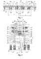
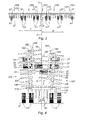
- Figures 1 and 2 show a machine according to a first embodiment of the invention, seen from the rear, respectively unfolded working position and folded transport position.
- Said machine is intended to work or treat a large width of terrain, for this purpose it consists of a central section 1, two median side sections 2 and 3 of width L and two lateral end sections 4 and 5.
- the medial lateral sections 2, 3 are hinged on either side of said central section 1, on the lateral edges thereof, respectively by the hinges 12 and 13.
- the lateral end sections 4, 5 are articulated on either side of the medial lateral sections 2, 3, on the external lateral edges thereof, respectively by the articulations 24 and 35.
- Means of known type such as hydraulic cylinders not shown in the drawing, allow the tilting of the sections relative to each other during folding of the machine for road traffic and unfolding thereof.
- Each section 1 to 5 is equipped with at least one beam 10, 20, 30, 40, 50 carrying tools, respectively 61, 62, 63, 64, 65, for working or treating the soil and is equipped with wheels 11, 21, 31, 41, 51.
- the central section 1 does not carry tools.
- Each tool is preferably a soil penetration tool consisting each time of at least one stanchion and a wear part such as plowshare, blade, coulter or tooth.
- the central section 1 is equipped with two pairs of wheels 11 arranged near the lateral ends of the beam 10, the median lateral sections 2, 3 are each equipped with a pair of wheels 21, 31 and the lateral end sections 4, 5 are each equipped with a wheel 41, 51.
- the wheels are evenly distributed along the machine so as to support the weight thereof and to distribute the support force to the ground S.
- Said wheels 11 to 51 are carried by mounting means 17 to 57 pivotally mounted on the beams 10 to 50 so as to adjust the height of said beams relative to the ground S.
- said beams 10 to 50 are in said high position for which the tools are spaced from the ground. This position is used for maneuvers at the headland.
- Figure 1 the sections thereof extending generally horizontally in the same plane. Said sections are generally in the same horizontal plane when the ground is flat and are free to move angularly relative to each other to follow the undulations of the ground.
- two lateral sections here the lateral end sections 4, 5 are positioned vertically above the central section 1 with their tools 64, 65 facing each other.
- the joints 12, 13 are not positioned at the lateral ends of the beam 10 but at a distance from said ends.
- the distance separating said hinges 12, 13 from the lateral ends of the beam 10 is such that the distance between the ends of the tools 62, 63 of the median lateral sections 2, 3 respects the road gauge.
- the beams 40, 50 are, in their folded vertical position, spaced from each other by a distance greater than the height of a tool but less than twice the height of a tool.
- the lateral sections are formed of at least one beam-type frame carrying tools axially offset in the forward-back direction taken in the direction of movement of the machine to delimit a plurality of rows of tools.
- the tools are evenly distributed over the entire width thereof.
- said tools are further distributed symmetrically with respect to the central axis CC of the machine.
- the tools are not arranged symmetrically with respect to the central axis CC of the machine.
- the first tool disposed to the left of the central axis CC is at the distance X of the latter, while the first tool disposed to the right of said central axis CC is at the distance Y.
- X is smaller than Y.
- the nth tool to the right of the central axis CC is farther away from said center axis than the nth tool on the left.
- said tools of an end section When viewed from behind the machine in the folded position, said tools of an end section are inserted between the tools of the other side section facing them by being positioned alternately in the vertical direction. which creates an overlap by superposition of said tools.
- the width of the folded machine is equal to four beam thicknesses plus between three and four times the height of the tools.
- the overlap between the tools facing each other is at least one third of the height of a tool.
- the tools overlap almost to their full height so that the width of the machine in the folded position is reduced by about a tool height compared to known machines such as that shown in FIG. WO 98/47344.
- the machine according to the invention can be equipped with tools of greater height than the tools usually used in this type of machine.
- the machine according to the invention is then more efficient because of the reduction of the risk of jamming, the increase in the working depth, etc.
- the tools are arranged symmetrically with respect to the central axis CC of the machine as in known machines, the two tools arranged on either side of the machine.
- median axis CC are at the same distance Z thereof.
- the joints 124 and 135 between the medial lateral sections 102, 103 and the lateral end sections 104, 105 are not disposed symmetrically with respect to said central axis CC.
- the hinge 135 is disposed at the distance T from the central axis CC while the hinge 124 is disposed at the distance U, less than T, of said central axis.
- Said tools are thus alternated in the vertical direction.
- Figure 5 is a top view of a hitch comprising a machine according to the invention coupled to a tractor A.
- the working or soil treatment machines usually comprise several rows of tools arranged axially one after the other in the direction of travel of the hitch.
- tools seen next to each other when the machine is viewed from the rear are arranged axially at a distance from each other. It is thus possible to provide machines carrying a large number of tools in the transverse direction and allowing work or treatment of the earth in furrows very close to each other.
- the tools of the lateral end sections 204, 205 are offset axially with respect to each other.
- the tools 641, 642, 643, 644 and 645 of the end lateral section 204 are respectively axially in front of the tools 651, 652 in the direction of travel of the coupling. , 653, 654 and 655 of the end lateral section 205.
- the beams 240, 250 are for this purpose of different shapes.
- This arrangement makes it possible to further promote the insertion of the tools carried by a lateral section into free spaces separating the tools of the other lateral section facing them when the machine is folded.
- said tools can thus be positioned alternately in the vertical direction, the one above the other, forming an overlapping overlap of the tools, that in the axial direction, one after the other in the axial direction of movement of the machine, forming an overlap by juxtaposition of the tools.
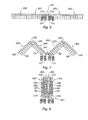
- Figures 6 to 8 show a machine according to another embodiment of the present invention wherein the side sections 302, 303 are hinged to the central section 301 at hinge points 312, 313 close to each other and positioned near the center of the beam 310 of said central section 301.
- only the central section 301 carries wheels 11.
- at least some of the lateral sections carry wheels or rollers.
- the side end sections 304, 305 are connected to the medial side sections 302, 303 by link rods 324, 335.
- the configuration of the machine in the folded transport position is different from that described above.
- the beams 320, 330 of the median lateral sections 302, 303 extend perpendicularly to the beam 310 of the central section 301 while being positioned one beside the other and the beams 340, 350 side end sections 304, 305 are disposed on either side of said beams 320, 330, near the side faces of the machine.
- each middle lateral section 302 here each middle lateral section 302, respectively 303, with each end lateral section 304, respectively 305, are positioned vertically above the central section 301 with their tools.
- the beams 320, 340, 330, 350 are, in their folded vertical position, spaced apart from one another by a distance greater than the height of a tool but less than twice the height of a tool.
Landscapes
- Life Sciences & Earth Sciences (AREA)
- Engineering & Computer Science (AREA)
- Mechanical Engineering (AREA)
- Soil Sciences (AREA)
- Environmental Sciences (AREA)
- Agricultural Machines (AREA)
- Soil Working Implements (AREA)
Applications Claiming Priority (1)
| Application Number | Priority Date | Filing Date | Title |
|---|---|---|---|
| FR0501822A FR2882218B1 (fr) | 2005-02-23 | 2005-02-23 | Machine pour le travail ou le traitement d'une grande largeur de terrain |
Publications (2)
| Publication Number | Publication Date |
|---|---|
| EP1695603A1 true EP1695603A1 (de) | 2006-08-30 |
| EP1695603B1 EP1695603B1 (de) | 2017-03-29 |
Family
ID=35395887
Family Applications (1)
| Application Number | Title | Priority Date | Filing Date |
|---|---|---|---|
| EP06290302.6A Expired - Lifetime EP1695603B1 (de) | 2005-02-23 | 2006-02-22 | Bodenbearbeitungs- und Bodenbehandlungsmaschine mit grosser Breite |
Country Status (2)
| Country | Link |
|---|---|
| EP (1) | EP1695603B1 (de) |
| FR (1) | FR2882218B1 (de) |
Cited By (2)
| Publication number | Priority date | Publication date | Assignee | Title |
|---|---|---|---|---|
| WO2017076376A1 (en) * | 2015-11-07 | 2017-05-11 | Farmet, A.S. | Agricultural machine for soil cultivation |
| EP3311646A1 (de) * | 2016-10-21 | 2018-04-25 | CNH Industrial Belgium NV | Zusammenklappbares kopfteil |
Citations (3)
| Publication number | Priority date | Publication date | Assignee | Title |
|---|---|---|---|---|
| US4867245A (en) * | 1988-08-15 | 1989-09-19 | Deere & Company | Wing fold implement with latching structure |
| DE19716801A1 (de) | 1997-04-22 | 1998-10-29 | Horsch Maschinen Gmbh | Werkzeugträger für Bodenbearbeitungs- und Bodenbehandlungsmaschinen |
| EP1008286A1 (de) | 1998-12-10 | 2000-06-14 | Amazonen-Werke H. Dreyer GmbH & Co. KG | Werkzeugträger |
-
2005
- 2005-02-23 FR FR0501822A patent/FR2882218B1/fr not_active Expired - Fee Related
-
2006
- 2006-02-22 EP EP06290302.6A patent/EP1695603B1/de not_active Expired - Lifetime
Patent Citations (4)
| Publication number | Priority date | Publication date | Assignee | Title |
|---|---|---|---|---|
| US4867245A (en) * | 1988-08-15 | 1989-09-19 | Deere & Company | Wing fold implement with latching structure |
| DE19716801A1 (de) | 1997-04-22 | 1998-10-29 | Horsch Maschinen Gmbh | Werkzeugträger für Bodenbearbeitungs- und Bodenbehandlungsmaschinen |
| WO1998047344A2 (de) | 1997-04-22 | 1998-10-29 | Horsch Maschinen Gmbh | Werkzeugträger für bodenbearbeitungs- und bodenbehandlungsmaschinen |
| EP1008286A1 (de) | 1998-12-10 | 2000-06-14 | Amazonen-Werke H. Dreyer GmbH & Co. KG | Werkzeugträger |
Cited By (7)
| Publication number | Priority date | Publication date | Assignee | Title |
|---|---|---|---|---|
| WO2017076376A1 (en) * | 2015-11-07 | 2017-05-11 | Farmet, A.S. | Agricultural machine for soil cultivation |
| PL127333U1 (de) * | 2015-11-07 | 2019-02-11 | ||
| RU192572U1 (ru) * | 2015-11-07 | 2019-09-23 | ФАРМЕТ,а.с. | Сельскохозяйственная машина для обработки почвы |
| CZ308271B6 (cs) * | 2015-11-07 | 2020-04-08 | Farmet A.S. | Zemědělský stroj na zpracování půdy |
| EP3311646A1 (de) * | 2016-10-21 | 2018-04-25 | CNH Industrial Belgium NV | Zusammenklappbares kopfteil |
| BE1024679B1 (nl) * | 2016-10-21 | 2018-05-22 | Cnh Industrial Belgium Nv | Vouwbaar maaibord |
| US10405482B2 (en) | 2016-10-21 | 2019-09-10 | Cnh Industrial America Llc | Foldable header |
Also Published As
| Publication number | Publication date |
|---|---|
| FR2882218A1 (fr) | 2006-08-25 |
| EP1695603B1 (de) | 2017-03-29 |
| FR2882218B1 (fr) | 2007-04-06 |
Similar Documents
| Publication | Publication Date | Title |
|---|---|---|
| CA2535238C (fr) | Engin agricole pour la coupe de produits | |
| EP2699074B1 (de) | Landwirtschaftliche maschine mit verbesserter faltvorrichtung | |
| EP2451265A1 (de) | Pflanzenernte-/verpackungsmaschine mit einer vorrichtung zur gleichmässigen verteilung von auf den boden zurückgegebenen pflanzen | |
| FR2756699A1 (fr) | Machine agricole de preparation de la terre a outils independants | |
| EP2923539B1 (de) | Sämaschine mit integrierter walze zum zerstören einer vegetationsdeckschicht | |
| EP1695603B1 (de) | Bodenbearbeitungs- und Bodenbehandlungsmaschine mit grosser Breite | |
| FR2604331A1 (fr) | Machine centrifuge pour la fenaison | |
| EP4039073B1 (de) | Klappvorrichtung für transport mit gelenkmechanismus | |
| FR2935218A1 (fr) | Charrue portee comportant un bras de roue perfectionne. | |
| FR3007934A1 (fr) | Machine de travail du sol avec un dispositif de reglage de la profondeur de travail perfectionne | |
| FR2543784A1 (fr) | Cultivateur de retournement de sol | |
| EP2534934B1 (de) | Sämaschine mit einer Walze, die aus verschobener Abschnitte besteht | |
| EP4144196B1 (de) | Landwirtschaftliche vorrichtung mit zwei arbeitseinheiten | |
| EP0966875B1 (de) | Sähmaschine | |
| EP2314140A1 (de) | Landwirtschaftliche Maschine für die Aussaat mit einem zusätzlichen Andruckmittel | |
| FR2923676A1 (fr) | Dispositif pour le dechiquetage et le broyage de vegetaux au sol, attelable a un vehicule tracteur. | |
| WO2005015974A2 (fr) | Machine combinee forestiere pour le travail du sol | |
| EP3403481A1 (de) | Werkzeughalterahmen für die bodenbearbeitung mit begrenzter verschiebung | |
| FR3066067B1 (fr) | Chassis porte outils de travail du sol comportant deux troncons arriere lateraux repliables et un troncon arriere central mobile | |
| EP4736609A1 (de) | Bodenbearbeitungsmaschine | |
| FR2550909A1 (fr) | Machine pour travailler le sol munie d'un attelage perfectionne | |
| FR2971388A1 (fr) | Andaineur de pierres | |
| CA3074078A1 (fr) | Machine agricole et procede de pliage d'une machine agricole | |
| FR2651407A1 (fr) | Machine de preparation du sol avant ensemencement. | |
| FR2589312A1 (fr) | Machine pour travailler le sol munie d'un attelage perfectionne |
Legal Events
| Date | Code | Title | Description |
|---|---|---|---|
| PUAI | Public reference made under article 153(3) epc to a published international application that has entered the european phase |
Free format text: ORIGINAL CODE: 0009012 |
|
| AK | Designated contracting states |
Kind code of ref document: A1 Designated state(s): AT BE BG CH CY CZ DE DK EE ES FI FR GB GR HU IE IS IT LI LT LU LV MC NL PL PT RO SE SI SK TR |
|
| AX | Request for extension of the european patent |
Extension state: AL BA HR MK YU |
|
| 17P | Request for examination filed |
Effective date: 20070126 |
|
| 17Q | First examination report despatched |
Effective date: 20070227 |
|
| AKX | Designation fees paid |
Designated state(s): AT BE BG CH CY CZ DE DK EE ES FI FR GB GR HU IE IS IT LI LT LU LV MC NL PL PT RO SE SI SK TR |
|
| GRAP | Despatch of communication of intention to grant a patent |
Free format text: ORIGINAL CODE: EPIDOSNIGR1 |
|
| INTG | Intention to grant announced |
Effective date: 20161027 |
|
| GRAS | Grant fee paid |
Free format text: ORIGINAL CODE: EPIDOSNIGR3 |
|
| GRAA | (expected) grant |
Free format text: ORIGINAL CODE: 0009210 |
|
| AK | Designated contracting states |
Kind code of ref document: B1 Designated state(s): AT BE BG CH CY CZ DE DK EE ES FI FR GB GR HU IE IS IT LI LT LU LV MC NL PL PT RO SE SI SK TR |
|
| REG | Reference to a national code |
Ref country code: GB Ref legal event code: FG4D Free format text: NOT ENGLISH |
|
| REG | Reference to a national code |
Ref country code: CH Ref legal event code: EP |
|
| REG | Reference to a national code |
Ref country code: AT Ref legal event code: REF Ref document number: 878892 Country of ref document: AT Kind code of ref document: T Effective date: 20170415 |
|
| REG | Reference to a national code |
Ref country code: IE Ref legal event code: FG4D Free format text: LANGUAGE OF EP DOCUMENT: FRENCH |
|
| REG | Reference to a national code |
Ref country code: DE Ref legal event code: R096 Ref document number: 602006052091 Country of ref document: DE |
|
| REG | Reference to a national code |
Ref country code: SE Ref legal event code: TRGR |
|
| PG25 | Lapsed in a contracting state [announced via postgrant information from national office to epo] |
Ref country code: FI Free format text: LAPSE BECAUSE OF FAILURE TO SUBMIT A TRANSLATION OF THE DESCRIPTION OR TO PAY THE FEE WITHIN THE PRESCRIBED TIME-LIMIT Effective date: 20170329 Ref country code: LT Free format text: LAPSE BECAUSE OF FAILURE TO SUBMIT A TRANSLATION OF THE DESCRIPTION OR TO PAY THE FEE WITHIN THE PRESCRIBED TIME-LIMIT Effective date: 20170329 Ref country code: GR Free format text: LAPSE BECAUSE OF FAILURE TO SUBMIT A TRANSLATION OF THE DESCRIPTION OR TO PAY THE FEE WITHIN THE PRESCRIBED TIME-LIMIT Effective date: 20170630 |
|
| REG | Reference to a national code |
Ref country code: NL Ref legal event code: MP Effective date: 20170329 |
|
| REG | Reference to a national code |
Ref country code: AT Ref legal event code: MK05 Ref document number: 878892 Country of ref document: AT Kind code of ref document: T Effective date: 20170329 |
|
| PG25 | Lapsed in a contracting state [announced via postgrant information from national office to epo] |
Ref country code: BG Free format text: LAPSE BECAUSE OF FAILURE TO SUBMIT A TRANSLATION OF THE DESCRIPTION OR TO PAY THE FEE WITHIN THE PRESCRIBED TIME-LIMIT Effective date: 20170629 Ref country code: LV Free format text: LAPSE BECAUSE OF FAILURE TO SUBMIT A TRANSLATION OF THE DESCRIPTION OR TO PAY THE FEE WITHIN THE PRESCRIBED TIME-LIMIT Effective date: 20170329 |
|
| PG25 | Lapsed in a contracting state [announced via postgrant information from national office to epo] |
Ref country code: NL Free format text: LAPSE BECAUSE OF FAILURE TO SUBMIT A TRANSLATION OF THE DESCRIPTION OR TO PAY THE FEE WITHIN THE PRESCRIBED TIME-LIMIT Effective date: 20170329 |
|
| PG25 | Lapsed in a contracting state [announced via postgrant information from national office to epo] |
Ref country code: EE Free format text: LAPSE BECAUSE OF FAILURE TO SUBMIT A TRANSLATION OF THE DESCRIPTION OR TO PAY THE FEE WITHIN THE PRESCRIBED TIME-LIMIT Effective date: 20170329 Ref country code: CZ Free format text: LAPSE BECAUSE OF FAILURE TO SUBMIT A TRANSLATION OF THE DESCRIPTION OR TO PAY THE FEE WITHIN THE PRESCRIBED TIME-LIMIT Effective date: 20170329 Ref country code: RO Free format text: LAPSE BECAUSE OF FAILURE TO SUBMIT A TRANSLATION OF THE DESCRIPTION OR TO PAY THE FEE WITHIN THE PRESCRIBED TIME-LIMIT Effective date: 20170329 Ref country code: ES Free format text: LAPSE BECAUSE OF FAILURE TO SUBMIT A TRANSLATION OF THE DESCRIPTION OR TO PAY THE FEE WITHIN THE PRESCRIBED TIME-LIMIT Effective date: 20170329 Ref country code: SK Free format text: LAPSE BECAUSE OF FAILURE TO SUBMIT A TRANSLATION OF THE DESCRIPTION OR TO PAY THE FEE WITHIN THE PRESCRIBED TIME-LIMIT Effective date: 20170329 Ref country code: AT Free format text: LAPSE BECAUSE OF FAILURE TO SUBMIT A TRANSLATION OF THE DESCRIPTION OR TO PAY THE FEE WITHIN THE PRESCRIBED TIME-LIMIT Effective date: 20170329 |
|
| PG25 | Lapsed in a contracting state [announced via postgrant information from national office to epo] |
Ref country code: PL Free format text: LAPSE BECAUSE OF FAILURE TO SUBMIT A TRANSLATION OF THE DESCRIPTION OR TO PAY THE FEE WITHIN THE PRESCRIBED TIME-LIMIT Effective date: 20170329 Ref country code: PT Free format text: LAPSE BECAUSE OF FAILURE TO SUBMIT A TRANSLATION OF THE DESCRIPTION OR TO PAY THE FEE WITHIN THE PRESCRIBED TIME-LIMIT Effective date: 20170731 Ref country code: IS Free format text: LAPSE BECAUSE OF FAILURE TO SUBMIT A TRANSLATION OF THE DESCRIPTION OR TO PAY THE FEE WITHIN THE PRESCRIBED TIME-LIMIT Effective date: 20170729 |
|
| REG | Reference to a national code |
Ref country code: DE Ref legal event code: R097 Ref document number: 602006052091 Country of ref document: DE |
|
| PG25 | Lapsed in a contracting state [announced via postgrant information from national office to epo] |
Ref country code: DK Free format text: LAPSE BECAUSE OF FAILURE TO SUBMIT A TRANSLATION OF THE DESCRIPTION OR TO PAY THE FEE WITHIN THE PRESCRIBED TIME-LIMIT Effective date: 20170329 |
|
| PLBE | No opposition filed within time limit |
Free format text: ORIGINAL CODE: 0009261 |
|
| STAA | Information on the status of an ep patent application or granted ep patent |
Free format text: STATUS: NO OPPOSITION FILED WITHIN TIME LIMIT |
|
| REG | Reference to a national code |
Ref country code: FR Ref legal event code: PLFP Year of fee payment: 13 |
|
| PG25 | Lapsed in a contracting state [announced via postgrant information from national office to epo] |
Ref country code: IT Free format text: LAPSE BECAUSE OF FAILURE TO SUBMIT A TRANSLATION OF THE DESCRIPTION OR TO PAY THE FEE WITHIN THE PRESCRIBED TIME-LIMIT Effective date: 20170329 |
|
| 26N | No opposition filed |
Effective date: 20180103 |
|
| PG25 | Lapsed in a contracting state [announced via postgrant information from national office to epo] |
Ref country code: SI Free format text: LAPSE BECAUSE OF FAILURE TO SUBMIT A TRANSLATION OF THE DESCRIPTION OR TO PAY THE FEE WITHIN THE PRESCRIBED TIME-LIMIT Effective date: 20170329 |
|
| REG | Reference to a national code |
Ref country code: CH Ref legal event code: PL |
|
| PG25 | Lapsed in a contracting state [announced via postgrant information from national office to epo] |
Ref country code: MC Free format text: LAPSE BECAUSE OF FAILURE TO SUBMIT A TRANSLATION OF THE DESCRIPTION OR TO PAY THE FEE WITHIN THE PRESCRIBED TIME-LIMIT Effective date: 20170329 |
|
| REG | Reference to a national code |
Ref country code: IE Ref legal event code: MM4A |
|
| REG | Reference to a national code |
Ref country code: BE Ref legal event code: MM Effective date: 20180228 |
|
| PG25 | Lapsed in a contracting state [announced via postgrant information from national office to epo] |
Ref country code: CH Free format text: LAPSE BECAUSE OF NON-PAYMENT OF DUE FEES Effective date: 20180228 Ref country code: LU Free format text: LAPSE BECAUSE OF NON-PAYMENT OF DUE FEES Effective date: 20180222 Ref country code: LI Free format text: LAPSE BECAUSE OF NON-PAYMENT OF DUE FEES Effective date: 20180228 |
|
| PG25 | Lapsed in a contracting state [announced via postgrant information from national office to epo] |
Ref country code: IE Free format text: LAPSE BECAUSE OF NON-PAYMENT OF DUE FEES Effective date: 20180222 |
|
| PG25 | Lapsed in a contracting state [announced via postgrant information from national office to epo] |
Ref country code: BE Free format text: LAPSE BECAUSE OF NON-PAYMENT OF DUE FEES Effective date: 20180228 |
|
| PG25 | Lapsed in a contracting state [announced via postgrant information from national office to epo] |
Ref country code: TR Free format text: LAPSE BECAUSE OF FAILURE TO SUBMIT A TRANSLATION OF THE DESCRIPTION OR TO PAY THE FEE WITHIN THE PRESCRIBED TIME-LIMIT Effective date: 20170329 |
|
| PGFP | Annual fee paid to national office [announced via postgrant information from national office to epo] |
Ref country code: SE Payment date: 20200227 Year of fee payment: 15 Ref country code: DE Payment date: 20200227 Year of fee payment: 15 |
|
| PG25 | Lapsed in a contracting state [announced via postgrant information from national office to epo] |
Ref country code: HU Free format text: LAPSE BECAUSE OF FAILURE TO SUBMIT A TRANSLATION OF THE DESCRIPTION OR TO PAY THE FEE WITHIN THE PRESCRIBED TIME-LIMIT; INVALID AB INITIO Effective date: 20060222 |
|
| PG25 | Lapsed in a contracting state [announced via postgrant information from national office to epo] |
Ref country code: CY Free format text: LAPSE BECAUSE OF FAILURE TO SUBMIT A TRANSLATION OF THE DESCRIPTION OR TO PAY THE FEE WITHIN THE PRESCRIBED TIME-LIMIT Effective date: 20170329 |
|
| GBPC | Gb: european patent ceased through non-payment of renewal fee |
Effective date: 20200222 |
|
| PG25 | Lapsed in a contracting state [announced via postgrant information from national office to epo] |
Ref country code: GB Free format text: LAPSE BECAUSE OF NON-PAYMENT OF DUE FEES Effective date: 20200222 |
|
| REG | Reference to a national code |
Ref country code: DE Ref legal event code: R119 Ref document number: 602006052091 Country of ref document: DE |
|
| REG | Reference to a national code |
Ref country code: SE Ref legal event code: EUG |
|
| PG25 | Lapsed in a contracting state [announced via postgrant information from national office to epo] |
Ref country code: SE Free format text: LAPSE BECAUSE OF NON-PAYMENT OF DUE FEES Effective date: 20210223 |
|
| PG25 | Lapsed in a contracting state [announced via postgrant information from national office to epo] |
Ref country code: DE Free format text: LAPSE BECAUSE OF NON-PAYMENT OF DUE FEES Effective date: 20210901 |
|
| PGFP | Annual fee paid to national office [announced via postgrant information from national office to epo] |
Ref country code: FR Payment date: 20220216 Year of fee payment: 17 |
|
| PG25 | Lapsed in a contracting state [announced via postgrant information from national office to epo] |
Ref country code: FR Free format text: LAPSE BECAUSE OF NON-PAYMENT OF DUE FEES Effective date: 20230228 |