EP1696187A2 - Wärmetauscher zum Verbessern des thermischen Wirkungsgrades und Klimaanlage mit einem solchen Wärmetauscher - Google Patents
Wärmetauscher zum Verbessern des thermischen Wirkungsgrades und Klimaanlage mit einem solchen Wärmetauscher Download PDFInfo
- Publication number
- EP1696187A2 EP1696187A2 EP06000843A EP06000843A EP1696187A2 EP 1696187 A2 EP1696187 A2 EP 1696187A2 EP 06000843 A EP06000843 A EP 06000843A EP 06000843 A EP06000843 A EP 06000843A EP 1696187 A2 EP1696187 A2 EP 1696187A2
- Authority
- EP
- European Patent Office
- Prior art keywords
- refrigerant
- heat exchange
- air
- heat
- housing
- Prior art date
- Legal status (The legal status is an assumption and is not a legal conclusion. Google has not performed a legal analysis and makes no representation as to the accuracy of the status listed.)
- Withdrawn
Links
- 239000003507 refrigerant Substances 0.000 claims abstract description 173
- 238000001802 infusion Methods 0.000 claims abstract description 10
- 230000005540 biological transmission Effects 0.000 claims description 6
- 238000007664 blowing Methods 0.000 claims description 4
- 238000007599 discharging Methods 0.000 claims description 3
- 238000000034 method Methods 0.000 claims description 2
- 239000003570 air Substances 0.000 description 111
- 238000001816 cooling Methods 0.000 description 15
- 238000010438 heat treatment Methods 0.000 description 12
- 239000007788 liquid Substances 0.000 description 8
- 238000010276 construction Methods 0.000 description 5
- 230000000694 effects Effects 0.000 description 5
- 239000012080 ambient air Substances 0.000 description 3
- 239000007787 solid Substances 0.000 description 3
- 238000009834 vaporization Methods 0.000 description 3
- 230000008016 vaporization Effects 0.000 description 3
- 241000270295 Serpentes Species 0.000 description 2
- 230000002159 abnormal effect Effects 0.000 description 2
- 230000008859 change Effects 0.000 description 2
- 238000009833 condensation Methods 0.000 description 2
- 230000005494 condensation Effects 0.000 description 2
- 230000001351 cycling effect Effects 0.000 description 2
- 238000001704 evaporation Methods 0.000 description 2
- 238000012986 modification Methods 0.000 description 2
- 230000004048 modification Effects 0.000 description 2
- 239000000284 extract Substances 0.000 description 1
- 230000008569 process Effects 0.000 description 1
Images


Classifications
-
- A—HUMAN NECESSITIES
- A45—HAND OR TRAVELLING ARTICLES
- A45D—HAIRDRESSING OR SHAVING EQUIPMENT; EQUIPMENT FOR COSMETICS OR COSMETIC TREATMENTS, e.g. FOR MANICURING OR PEDICURING
- A45D8/00—Hair-holding devices; Accessories therefor
- A45D8/36—Hair straps; Hair rings
-
- F—MECHANICAL ENGINEERING; LIGHTING; HEATING; WEAPONS; BLASTING
- F24—HEATING; RANGES; VENTILATING
- F24F—AIR-CONDITIONING; AIR-HUMIDIFICATION; VENTILATION; USE OF AIR CURRENTS FOR SCREENING
- F24F1/00—Room units for air-conditioning, e.g. separate or self-contained units or units receiving primary air from a central station
- F24F1/06—Separate outdoor units, e.g. outdoor unit to be linked to a separate room comprising a compressor and a heat exchanger
- F24F1/26—Refrigerant piping
- F24F1/32—Refrigerant piping for connecting the separate outdoor units to indoor units
-
- A—HUMAN NECESSITIES
- A45—HAND OR TRAVELLING ARTICLES
- A45D—HAIRDRESSING OR SHAVING EQUIPMENT; EQUIPMENT FOR COSMETICS OR COSMETIC TREATMENTS, e.g. FOR MANICURING OR PEDICURING
- A45D8/00—Hair-holding devices; Accessories therefor
- A45D8/002—Accessories therefor
-
- A—HUMAN NECESSITIES
- A45—HAND OR TRAVELLING ARTICLES
- A45D—HAIRDRESSING OR SHAVING EQUIPMENT; EQUIPMENT FOR COSMETICS OR COSMETIC TREATMENTS, e.g. FOR MANICURING OR PEDICURING
- A45D8/00—Hair-holding devices; Accessories therefor
- A45D8/004—Hair-holding devices; Accessories therefor with decorative arrangements or form
- A45D8/006—Interchangeable ornaments attached to hair holding devices
-
- F—MECHANICAL ENGINEERING; LIGHTING; HEATING; WEAPONS; BLASTING
- F24—HEATING; RANGES; VENTILATING
- F24F—AIR-CONDITIONING; AIR-HUMIDIFICATION; VENTILATION; USE OF AIR CURRENTS FOR SCREENING
- F24F1/00—Room units for air-conditioning, e.g. separate or self-contained units or units receiving primary air from a central station
- F24F1/0007—Indoor units, e.g. fan coil units
- F24F1/0043—Indoor units, e.g. fan coil units characterised by mounting arrangements
- F24F1/0057—Indoor units, e.g. fan coil units characterised by mounting arrangements mounted in or on a wall
-
- F—MECHANICAL ENGINEERING; LIGHTING; HEATING; WEAPONS; BLASTING
- F24—HEATING; RANGES; VENTILATING
- F24F—AIR-CONDITIONING; AIR-HUMIDIFICATION; VENTILATION; USE OF AIR CURRENTS FOR SCREENING
- F24F1/00—Room units for air-conditioning, e.g. separate or self-contained units or units receiving primary air from a central station
- F24F1/0007—Indoor units, e.g. fan coil units
- F24F1/0059—Indoor units, e.g. fan coil units characterised by heat exchangers
- F24F1/0063—Indoor units, e.g. fan coil units characterised by heat exchangers by the mounting or arrangement of the heat exchangers
-
- F—MECHANICAL ENGINEERING; LIGHTING; HEATING; WEAPONS; BLASTING
- F24—HEATING; RANGES; VENTILATING
- F24F—AIR-CONDITIONING; AIR-HUMIDIFICATION; VENTILATION; USE OF AIR CURRENTS FOR SCREENING
- F24F1/00—Room units for air-conditioning, e.g. separate or self-contained units or units receiving primary air from a central station
- F24F1/0007—Indoor units, e.g. fan coil units
- F24F1/0059—Indoor units, e.g. fan coil units characterised by heat exchangers
- F24F1/0067—Indoor units, e.g. fan coil units characterised by heat exchangers by the shape of the heat exchangers or of parts thereof, e.g. of their fins
-
- F—MECHANICAL ENGINEERING; LIGHTING; HEATING; WEAPONS; BLASTING
- F24—HEATING; RANGES; VENTILATING
- F24F—AIR-CONDITIONING; AIR-HUMIDIFICATION; VENTILATION; USE OF AIR CURRENTS FOR SCREENING
- F24F1/00—Room units for air-conditioning, e.g. separate or self-contained units or units receiving primary air from a central station
- F24F1/06—Separate outdoor units, e.g. outdoor unit to be linked to a separate room comprising a compressor and a heat exchanger
- F24F1/26—Refrigerant piping
-
- F—MECHANICAL ENGINEERING; LIGHTING; HEATING; WEAPONS; BLASTING
- F25—REFRIGERATION OR COOLING; COMBINED HEATING AND REFRIGERATION SYSTEMS; HEAT PUMP SYSTEMS; MANUFACTURE OR STORAGE OF ICE; LIQUEFACTION SOLIDIFICATION OF GASES
- F25B—REFRIGERATION MACHINES, PLANTS OR SYSTEMS; COMBINED HEATING AND REFRIGERATION SYSTEMS; HEAT PUMP SYSTEMS
- F25B39/00—Evaporators; Condensers
Definitions
- the document relates to an air conditioner. More particularly, the document relates to a heat exchanger for air conditioner configured to prevent refrigerant from being excessively concentrated to a particular heat exchange line.
- the air conditioner refers to a cooler for cooling an indoor air and a heater for heating the indoor air.
- the air conditioner is developed to a multi-type air conditioner which can cool and heat at the same time enabling to cool or heat all the rooms in the same operation mode for maintaining a more comfortable room environment without being influenced from external weather or environment.
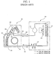
- FIG. 1 is a representation schematically illustrating a multi-type air conditioner according to the prior art.
- the air conditioner shown in FIG.1 largely includes an outdoor unit (10) installed in outdoor and an indoor heat exchanger (20) installed in indoor.
- the outdoor unit (10) further includes a compressor (11) for compressing refrigerant to high pressure and high temperature, an outdoor heat exchanger (12) for heat exchanging the refrigerant with an outdoor air, an outdoor fan device (13) for forcibly blowing ambient air of the outdoor heat exchanger (12) to promote the heat exchange of the outdoor heat exchanger (12), and an expansion device (14) for adiabatic expansion of the refrigerant.
- the indoor heat exchanger (20) includes first and second heat exchange lines (21. 22) in which the refrigerant circulates, and an indoor fan device (23) for forcibly blowing the ambient air of the indoor heat changer (20).
- a refrigerant circle (a refrigerant cycling loop) is constructed in the form of the compressor (11)-the outdoor heat exchanger (12)-the expansion device (14)-the indoor heat exchanger (20).
- the outdoor heat exchanger (12) functions as a condensing device during cooling operation
- the indoor heat exchanger (20) functions as an evaporating device and the refrigerant is circulated in the solid arrow direction to form a cooling cycle.
- the refrigerant compressed in the compressor (11) to high temperature and high pressure in the cooling cycle is transferred to the outdoor heat exchanger (12), and the refrigerant in the outdoor heat exchanger (12) releases the heat in outdoor air to be condensed into a liquid refrigerant of middle temperature and high pressure state.
- the liquid refrigerant thus condensed passes the expansion device (14) is converted into a liquid refrigerant of low temperature and low pressure and transferred toward the indoor heat exchanger (20) via a first refrigerant tube (31).
- the refrigerant transferred to the first refrigerant pipe (31) is divided at first and second branched tubes (33. 34) and flows into the first and second heat exchange lines (21. 22) and extracts the heat from the indoor air to cool the indoor.
- the refrigerant having passed the first heat exchange line (21) while conducting the cooling operation is discharged via a third branched tube (35), and the refrigerant having passed the second heat exchange line (22) is discharged via a fourth branched tube (36) to be converged at a second refrigerant tube (32) and flows into the compressor (11).
- the outdoor heat exchanger (10) functions as an evaporating device during heating operation
- the indoor heat exchanger (20) functions as a condensing device, where the refrigerant circulates along the arrow illustrated in FIG.1 to form a heating cycling loop.
- the refrigerant in the heating cycle is compressed by the compressor (11) to flow toward the indoor heat exchanger (20) via the second refrigerant tube (32).
- the refrigerant having flowed toward the indoor heat exchanger (20) is divided by the first and second heat exchange lines (21. 22) via the third and fourth branched tubes (35. 36), and discharges heat into the indoor air and heats the indoor.
- the refrigerant having finished the heating process converges on the first refrigerant tube (31) to flow into the expansion device (14).
- the refrigerant at the expansion device (14) is converted to a liquid refrigerant of low temperature and low pressure, which in turn passes the outdoor heat exchanger (12) to evaporate to a gaseous refrigerant of low temperature and low pressure and returns to the compressor (11).
- FIG.2 illustrates a process in which the refrigerant in the indoor heat exchanger (20) heat-exchanges with the indoor air during the cooling and heating operations of the air conditioner.
- the indoor heat exchanger (20) is frontally disposed with air intakes (20a. 20b. 20c) for sucking the air, each at an appropriate location.
- the indoor heat exchanger (20) is further disposed thereunder at an appropriate location thereof with an air outlet (20d) for discharging the air forcibly blown by the indoor fan device (23), where the air is introduced to i 1 , i 2 , i 3 directions via air inlets (20a.20b.20c)and discharged to 'o' direction.
- the refrigerant of low pressure and low temperature branched via the first branched tube (33) flow into the first heat exchange line (21) and the refrigerant branched via the second branched tube (34) flows to the second heat exchange line (22).
- the first heat exchange line(21) is comprised of first through fourteenth tubes (21a) (21b) (21c) (21d) (21e) (21f) (21g) (21h) (21i) (21j) (21k) (21l )(21m)(21n)disposed on the indoor heat exchanger(20), and the second heat exchange line is comprised of first through fourteenth tubes (22a) (22b) (22c) (22d) (22e) (22f) (22g) (22h) (22i) (22j) (22k) (22l )(22m)(22n)disposed underneath the indoor heat exchanger (20).
- the refrigerant is circulated in low flow rate in the second heat exchange line (22) on top of the indoor heat exchanger (20) during the cooling operation due to brisk heat exchange and vaporization. Meanwhile, the refrigerant is circulated in high flow rate in the first heat exchange line (21) underneath the indoor heat exchanger (20) due to dull heat exchange and vaporization.
- the fifth through eighth tubes (21e through 21h) disposed at a lower end (A) of the first heat exchange line (21) can hardly contact the air, such that the refrigerant shows an abnormal circulation of low dryness at this end (A).
- the refrigerant of high pressure and high temperature is branched and flows to the first and second heat exchange lines (21.22) via the third and fourth branched tubes (35.36) along the arrow indicated in FIG.2.
- the refrigerant in the second heat exchange line (22) shows a high flow due to smooth heat exchange and condensation
- the refrigerant of high temperature and high pressure in the first heat exchange line (21) shows a low flow due to bad heat exchange and condensation.
- the fifth through eighth heat exchange tubes (21e through 21h) having less air contact experience an abnormal flow of high dryness.
- the present invention is disclosed to solve the aforementioned problems and it is an object of the present invention to provide a heat exchanger for an air conditioner, the heat exchanger configured to heat exchange by branching refrigerant into a plurality of heat exchange lines, the heat exchanger further configured to prevent the refrigerant from being excessively concentrated to a particular heat exchange line and to allow the refrigerant to flow evenly into all heat exchange lines.
- Another object is to provide an air conditioner having an improved structure of a heat exchanger by allowing an even flow rate of the refrigerant in all the heat exchange lines, thereby enabling to enhance the heating and cooling efficiency.
- a heat exchanger for an air conditioner comprising: a housing having at least one air inlet and at least one air outlet; and a plurality of heat exchange lines each disposed in the housing and branched from a refrigerant tube into which refrigerant branched via a refrigerant tube is infused and in which the refrigerant switches flowing directions along the respective interiors thereof, wherein the plurality of heat exchange lines are arranged in such a manner that each line crosses before and after an infusion direction of air introduced via the air inlet.
- an air conditioner comprising: a compressor for compressing refrigerant; an outdoor heat exchanger connected to the compressor to allow the refrigerant to move therein and for heat exchanging between the refrigerant and outside air; an expansion device connected to the outdoor heat exchanger for the refrigerant to move therein; and an indoor heat exchanger connected to the expansion device and the compressor via refrigerant tubes for the refrigerant to move therein and for heat exchanging between the refrigerant and indoor air
- the indoor heat exchanger comprises: a housing having at least one air inlet and at least one air outlet for infusing and discharging the indoor air; and a plurality of heat exchange lines respectively disposed inside the housing, and into which the refrigerant branched via the refrigerant tube is infused and in which the refrigerant flows along each interior thereof changing flow directions, and wherein the plurality of heat exchange lines are arranged in such a manner that each line crosses before and after the infusion directions of air introduced
- Each heat exchange line is substantially the same in diameter and length thereof, and the air quantity initially contacting each heat exchange line is substantially the same, out of the air infused into the housing via the air inlets, and the heat exchanged quantity of the refrigerant passing through each heat exchange line is substantially the same.
- refrigerant inlets of each heat exchange line are contiguous thereamong so as to converge at one side of an interior of the housing, and refrigerant outlets of each heat exchange line are contiguous thereamong so as to converge at one side of an interior of the housing.
- the heat exchanger may comprise: a heat transmission member coupled.to each heat exchange line for increasing a heat exchanging area of each heat exchange line; a housing having at least one air inlet and at least one air outlet; and a plurality of heat exchange lines into which refrigerant branched via a refrigerant tube is infused and in which the refrigerant switches flowing directions along the respective interiors thereof, wherein the plurality of heat exchange lines are arranged in such a manner that each line crosses before and after the infusion directions of air introduced via the air inlet.
- the refrigerant is prevented from being excessively concentrated to a particular heat exchange line and allowed to flow evenly into all heat exchange lines, because the heat exchanged refrigerant flowing along each branched heat exchange line shows the same quantity of flow rate at the entire heat exchange line.
- FIG.3 is a schematic exemplary structural view of a heat exchanger of an air conditioner according to the present invention
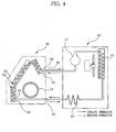
- FIG.4 is a schematic view illustrating a construction of an air conditioner disposed with a heat exchanger according to an embodiment of the present invention
- FIGS.5a and 5b are graphs each illustrating an operational effect of a heat exchanger according an embodiment of the present invention.
- a heat exchanger is used as an indoor heat exchanger of an air conditioner where an indoor heat exchanger and an outdoor heat exchanger are separately provided.
- the heat exchanger includes a housing (51) having air inlets (51a. 51b. 51c) and an air outlet (51d); and first and second heat exchange lines (52. 53) in which refrigerant flows and heat exchanges.with ambient air, and an indoor fan device (54) for forcibly blowing the air inside the housing (51) outside of the housing (51) via the air outlet (51d).
- the first heat exchange line (52) is disposed with first through fourteenth tubes (52a. 52b. 52c. 52d. 52e. 52f. 52g. 52h. 52i. 52j. 52k. 521. 52m. 52n), each approximately perpendicular to the air infused through the air inlets (51a. 51b. 51c), and connected to form an overall shape of a serpent.
- the flow direction of the refrigerant between the adjacent tubes is opposite.
- the first tube (52a) which is an inlet of the first heat exchange line (52) is connected to a first branched tube (63) and the fourteenth tube (52n) which is an outlet of the first heat exchange line (52) is connected to a third branched tube (65).
- the second heat exchange line (53) which corresponds as a structurally composing element to the first heat exchange line (52) is the same in diameter and length as those of the first heat exchange line (52).
- the second heat exchange line (53) is also disposed with first through fourteenth tubes (53a. 53b. 53c. 53d. 53e. 53f. 53g. 53h. 53i. 53j. 53k. 53l. 53m. 53n), each approximately perpendicular to the air infused through the air inlets (51a. 51b. 51c), and connected to form an overall shape of a serpent.
- the first tube (53a) which is an inlet of the second heat exchange line (53) is connected to a second branched tube (64) and the fourteenth tube (53n) which is an outlet is connected to a fourth branched tube (66).
- the first heat exchange line (52) and the second heat exchange line (53) cross each other before and after the air inlets (51a. 51b. 51c).
- the first heat exchange line (52) is arranged such that the third, fourth, seventh, eighth, tenth, eleventh and twelfth tubes (52c. 52d. 52g. 52h. 52j. 52k. 521) are disposed in front of the housing (51) which is in front of the second heat exchange line (53).
- the other remaining first, second, fifth, sixth, ninth, thirteenth and fourteenth tubes (52a. 52b. 52e. 52f. 52i. 52m. 52n) are disposed behind the housing (51) which is behind the second heat exchange line (53).
- the second heat exchange line (53) is arranged such that the first, second, fifth, sixth, ninth, tenth, thirteenth and fourteenth tubes (53a. 53b. 53e. 53f. 53i. 53j. 53m. 53n) are disposed in front of the first heat exchange line (52) which is at the rear of the housing (51), and the remaining third, fourth, seventh, eighth, eleventh and twelfth tubes (53c. 53d. 53g. 53h. 53k. 531) are disposed at the rear of the first heat exchange line (52) which is at the rear of the housing (51).
- Each first tube (52a. 53a) of the first and second heat exchange lines (52. 53) where the refrigerant is infused and discharged are adjacently disposed therebetween at one side of front lower end of the housing (51), and the fourteenth tubes (52n. 53n) which are respectively another inlet and outlet of refrigerant of the first and second heat exchange lines (52. 53) are adjacently disposed therebetween at one side of rear upper end of the housing (51).
- Each tube of the first and second heat exchange lines (52. 53) where the refrigerant flows is coupled to a heat transmission member (55) for increasing the air contact area so that the heat exchanges of refrigerant can be briskly performed.
- a heat exchanging device disposed with a heat exchanger includes a compressor (41) for compressing refrigerant; an outdoor heat exchanger (42) connected to the compressor (41) to allow the refrigerant to move therein and for heat exchanging between the refrigerant and outside air; an expansion device (43) connected to the outdoor heat exchanger (42) for the refrigerant to move therein; and an indoor heat exchanger (50) connected to the expansion device (43) and the compressor (41) via first and second refrigerant tubes (61. 62) for the refrigerant to move therein and for heat exchanging between the refrigerant and indoor air.
- the refrigerant flows toward a solid arrow.
- the refrigerant in the cooling cycle is initially compressed in the compressor (41) to high temperature and high pressure and is condensed to a liquid refrigerant of high pressure and middle temperature.
- the refrigerant thus condensed passes the expansion device (43) to be changed to liquid refrigerant of low temperature and low pressure, and flows toward the indoor heat exchanger (50) via the first refrigerant tube (61).
- the refrigerant flowing along the first refrigerant tube (61) is branched into the first and second heat exchange lines (52. 53) by the first and second branched tubes (63. 64) connected to the first refrigerant tube (61) and is kept flowing.
- the refrigerant transmitted via the first refrigerant tube (61) zigzags from the first tube (52a) to the fourteenth tube (52n) of the first heat exchange line (52) and is heat exchanged by the driving of the indoor fan device (54) with the indoor air infused into the housing (51) via the air inlets (51a. 51b. 51c).
- the refrigerant transmitted to the second refrigerant tube (64) zigzags from the first tube (53a) to the fourteenth tube (53n) of the second heat exchange line (53) to heat exchange with the indoor air infused into the housing (51).
- the heat exchange is briskly realized at the first, second, fifth, sixth, ninth, tenth, thirteenth and fourteenth tubes (53a. 53b. 53e. 53f. 53i. 53j. 53m. 53n) adjacent to the air inlets (51a. 51b. 51c), and when the refrigerant passes the third, fourth, seventh, eighth, eleventh and twelfth tubes (53c. 53d. 53g. 53h. 53k. 531) at the rear of the first heat exchange line (52); the heat exchange is a bit dulled.
- the refrigerant having passed the last fourteenth tube (53n) of the second heat exchange line (53) slips out via the fourth branched tube (66).
- the heat exchanged quantity at the first and second heat exchange lines (52. 53) is substantially the same because the tenth, eleventh and twelfth tubes (52j. 52k. 521) of the first heat exchange line (52) are disposed near the air inlet (51a) above the housing (51) where the air infusion quantity is large.
- the refrigerant discharged into the third and fourth branched tubes (65. 66) merges at the second refrigerant tube (62) and is returned to the compressor (41), and the heat exchanged air is discharged by the drive of the indoor fan device (54) to the '0' direction via the air outlet (51d).
- the refrigerant of high pressure and high temperature discharged from the compressor (41) flows toward the indoor heat exchanger (50) along the second refrigerant tube (62).
- the refrigerant flowing along the second refrigerant tube (62) is branched by the third and fourth branched tubes (65. 66) to flow toward the first and second heat exchange lines (52. 53), as shown in FIG.3.
- the refrigerant flowing toward the third branched tube (65) is infused into the fourteenth tube (52n) to zigzag along each tube and is heat exchanged with the indoor air introduced in the housing (51).
- the refrigerant flowing toward the fourth branched tube (66) is introduced into the fourteenth tube (53n) and passes each tube to flow to the first tube (53a) and to discharge heat via the air infused into the housing (51).
- the air quantity initially contacting the first heat exchange line (52) and the air quantity initially contacting second heat exchange line (53) are the same, out of the air introduced into the housing (51) via the air inlets (51a. 51b. 51c), whereby the heat exchange quantity of refrigerant at each heat exchange line (52. 53) is the same.
- the refrigerant flows in the same quantity and in the same state in the first and second heat exchange lines (52. 53) without showing any flow abnormalcy where the refrigerant is over-cooled due to over-discharge of heat from a certain heat exchange line and the refrigerant shows a high dryness due to insufficient heat exchange at a certain heat exchange line.
- the air heated by the heat exchange of the refrigerant is discharged outside of the housing (51) via the air outlet (51d) by the drive of the indoor fan device (54). Furthermore, the refrigerant having heated the indoor air and slipped out of the first tube (52a) of the first heat exchange line (52) and the refrigerant having slipped out of the first tube (53a) of the second heat exchange line (53) converge at the first refrigerant tube (61) and flows toward the outdoor unit (40).
- the refrigerant is transformed to liquid refrigerant of low temperature and low pressure at the expansion device (43), to flow toward the outdoor heat exchanger (42), and the refrigerant is vaporized to a gas of low temperature and low pressure at the outdoor heat exchanger (42) and is returned to the compressor (41).
- FIG.5a it shows that, if Coefficient of Performance (COP) of an air conditioner using the conventional heat exchanger is 3.03 during cooling operation, the COP of an air conditioner using the heat exchanger under the same condition according to the present invention is increased to 3.06, while the electric power consumption of a compressor drops to 1,209KW from 1,210KW.
- COP Coefficient of Performance
- an air conditioner using the conventional heat exchanger showed a COP of 3.37 during heating operation, and the electric power consumption of a compressor was 1,030W, while the COP was increased to 3.42 but electric power consumption of a compressor dropped to 1,026W when a heat exchanger according to the present invention was used under the same condition, showing that an overall performance of the air conditioner has been upgraded.
- FIG.6 is a schematic view illustrating a construction of an air conditioner disposed with a heat exchanger according to another embodiment of the present invention.
- the heat exchanger illustrated in FIG.6 according to another embodiment of the present invention also uses an indoor heat exchanger as the one in the above preferred embodiment.
- a first heat exchange line (52') and a second heat exchange line (S3') are so aligned as to cross each other before and after the air inlet direction.
- a first branched tube (63') branched from a first refrigerant tube (61') connected to an expansion device (43') is connected to a fourteenth tube (52n') of a first heat exchange line (52')
- a second branched tube (64') branched from a first refrigerant tube (61') is connected to a fourteenth tube (53n') which is a distal end of a second heat exchange line (53')
- a first tube (52a') of the first heat exchange line (52') is connected to a third branched tube (65') branched from a second refrigerant tube (62')
- a first tube (53a') of the second heat exchange line (53') is connected to a fourth branched tube (66').
- Other detailed description thereto will be omitted as construction, operation and effect are the same as those of the heat exchanger according to the hitherto-mentioned earlier preferred embodiment of the present invention.
- the present invention is not limited thereto, and can be applied to various heat exchangers using a plurality of heat exchange lines regardless of indoor heat exchanger or outdoor heat exchanger.
- heat exchange lines formed by being branched inside a heat exchanger are so aligned as to cross before and after an air inlet direction, such that the heat exchanged quantity between refrigerant and air at each heat exchange line is same, and the refrigerant is not biased to a particular heat exchange line but evenly flows in all the heat exchange lines. Consequently, a heat exchange efficiency of a heat exchanger can be improved.
- heat exchange efficiency of a heat exchanger is improved, cooling and heating efficiency of an air conditioner disposed with the improved heat exchanger can be enhanced at the same time.
Landscapes
- Engineering & Computer Science (AREA)
- Mechanical Engineering (AREA)
- General Engineering & Computer Science (AREA)
- Chemical & Material Sciences (AREA)
- Combustion & Propulsion (AREA)
- Physics & Mathematics (AREA)
- Thermal Sciences (AREA)
- Other Air-Conditioning Systems (AREA)
- Air Filters, Heat-Exchange Apparatuses, And Housings Of Air-Conditioning Units (AREA)
- Heat-Exchange Devices With Radiators And Conduit Assemblies (AREA)
Applications Claiming Priority (1)
| Application Number | Priority Date | Filing Date | Title |
|---|---|---|---|
| KR1020050008074A KR20060087173A (ko) | 2005-01-28 | 2005-01-28 | 공기조화장치용 열교환기 |
Publications (2)
| Publication Number | Publication Date |
|---|---|
| EP1696187A2 true EP1696187A2 (de) | 2006-08-30 |
| EP1696187A3 EP1696187A3 (de) | 2008-06-25 |
Family
ID=36297224
Family Applications (1)
| Application Number | Title | Priority Date | Filing Date |
|---|---|---|---|
| EP06000843A Withdrawn EP1696187A3 (de) | 2005-01-28 | 2006-01-16 | Wärmetauscher zum Verbessern des thermischen Wirkungsgrades und Klimaanlage mit einem solchen Wärmetauscher |
Country Status (5)
| Country | Link |
|---|---|
| US (1) | US20060168982A1 (de) |
| EP (1) | EP1696187A3 (de) |
| JP (1) | JP2006207998A (de) |
| KR (1) | KR20060087173A (de) |
| CN (1) | CN1811305A (de) |
Families Citing this family (9)
| Publication number | Priority date | Publication date | Assignee | Title |
|---|---|---|---|---|
| KR100814025B1 (ko) * | 2007-04-04 | 2008-03-17 | 삼성전자주식회사 | 공기조화기 |
| JP5447569B2 (ja) * | 2012-03-26 | 2014-03-19 | ダイキン工業株式会社 | 空気調和装置の熱交換器及び空気調和装置 |
| JP5772787B2 (ja) * | 2012-10-31 | 2015-09-02 | ダイキン工業株式会社 | 空気熱交換器 |
| WO2014091521A1 (ja) * | 2012-12-12 | 2014-06-19 | 三菱電機株式会社 | 空気調和機の室外ユニット |
| US20160187075A1 (en) * | 2014-12-29 | 2016-06-30 | Thermo King Corporation | Heat exchange units |
| WO2016155171A1 (zh) * | 2015-04-03 | 2016-10-06 | 广东美的制冷设备有限公司 | 制冷设备和用于制冷设备的换热器组件 |
| CN111433549A (zh) | 2017-07-17 | 2020-07-17 | 分形散热器技术有限责任公司 | 多重分形散热器系统及方法 |
| CN108825839A (zh) * | 2018-05-24 | 2018-11-16 | 中建三局安装工程有限公司 | 四管制风机盘管预制阀组 |
| CN113007923B (zh) * | 2021-03-12 | 2022-05-17 | 珠海格力电器股份有限公司 | 换热器及具有其的空调器 |
Citations (3)
| Publication number | Priority date | Publication date | Assignee | Title |
|---|---|---|---|---|
| JPH04359798A (ja) | 1991-06-04 | 1992-12-14 | Sharp Corp | 空気調和機 |
| US5542271A (en) | 1993-10-18 | 1996-08-06 | Hitachi, Ltd. | Air-conditioner employing non-azeotrope refrigerant |
| JP2003214723A (ja) | 2002-01-25 | 2003-07-30 | Hitachi Ltd | 空気調和機 |
Family Cites Families (17)
| Publication number | Priority date | Publication date | Assignee | Title |
|---|---|---|---|---|
| US1758643A (en) * | 1927-07-05 | 1930-05-13 | Baetz Henry | Air heater |
| US2669099A (en) * | 1950-12-29 | 1954-02-16 | Kramer Trenton Co | Evaporator construction for heat exchange systems |
| US4825664A (en) * | 1988-03-21 | 1989-05-02 | Kool-Fire Limited | High efficiency heat exchanger |
| JPH02144327A (ja) * | 1988-11-22 | 1990-06-04 | Sumikura Ind Co Ltd | 段積装置 |
| JP3594333B2 (ja) * | 1994-05-30 | 2004-11-24 | 三洋電機株式会社 | 熱交換器 |
| JPH0835740A (ja) * | 1994-07-22 | 1996-02-06 | Sanyo Electric Co Ltd | 熱交換器 |
| US5613554A (en) * | 1995-06-23 | 1997-03-25 | Heatcraft Inc. | A-coil heat exchanger |
| DE19540297C2 (de) * | 1995-10-28 | 1997-09-04 | Loh Kg Rittal Werk | Luft-Wasser-Wärmetauscher für einen Schaltschrank |
| DE19634450A1 (de) * | 1996-08-26 | 1998-03-05 | Basf Ag | Vorrichtung zur kontinuierlichen Durchführung chemischer Reaktionen |
| JPH1096525A (ja) * | 1996-09-20 | 1998-04-14 | Fujitsu General Ltd | 空気調和機 |
| US6142220A (en) * | 1996-10-02 | 2000-11-07 | Matsushita Electric Industrial Co., Ltd. | Finned heat exchanger |
| KR100261476B1 (ko) * | 1998-03-06 | 2000-07-01 | 윤종용 | 분리형 공기 조화기의 증발기 |
| JP2000081255A (ja) * | 1998-09-07 | 2000-03-21 | Sanyo Electric Co Ltd | 熱交換器 |
| US6543698B1 (en) * | 2000-04-10 | 2003-04-08 | Heat-N-Glo Fireplace Products, Inc. | Fireplace make-up air heat exchange system |
| KR20030058079A (ko) * | 2001-12-29 | 2003-07-07 | 주식회사 엘지이아이 | 열교환기의 조립방법 |
| US6991025B2 (en) * | 2004-03-17 | 2006-01-31 | Dana Canada Corporation | Cross-over rib pair for heat exchanger |
| JP4734915B2 (ja) * | 2004-12-24 | 2011-07-27 | ダイキン工業株式会社 | 熱交換器およびそれを備えた空気調和機の室内機 |
-
2005
- 2005-01-28 KR KR1020050008074A patent/KR20060087173A/ko not_active Ceased
-
2006
- 2006-01-16 EP EP06000843A patent/EP1696187A3/de not_active Withdrawn
- 2006-01-24 US US11/337,596 patent/US20060168982A1/en not_active Abandoned
- 2006-01-25 JP JP2006016351A patent/JP2006207998A/ja active Pending
- 2006-01-25 CN CNA2006100027654A patent/CN1811305A/zh active Pending
Patent Citations (3)
| Publication number | Priority date | Publication date | Assignee | Title |
|---|---|---|---|---|
| JPH04359798A (ja) | 1991-06-04 | 1992-12-14 | Sharp Corp | 空気調和機 |
| US5542271A (en) | 1993-10-18 | 1996-08-06 | Hitachi, Ltd. | Air-conditioner employing non-azeotrope refrigerant |
| JP2003214723A (ja) | 2002-01-25 | 2003-07-30 | Hitachi Ltd | 空気調和機 |
Also Published As
| Publication number | Publication date |
|---|---|
| CN1811305A (zh) | 2006-08-02 |
| EP1696187A3 (de) | 2008-06-25 |
| US20060168982A1 (en) | 2006-08-03 |
| JP2006207998A (ja) | 2006-08-10 |
| KR20060087173A (ko) | 2006-08-02 |
Similar Documents
| Publication | Publication Date | Title |
|---|---|---|
| EP2295877B1 (de) | Klimaanlage | |
| EP2636973B1 (de) | Verdampfer und kälteanlage mit dem verdampfer | |
| WO2008064251A2 (en) | Space-saving multichannel heat exchanger | |
| JP2003254555A (ja) | 空気調和機 | |
| EP1696187A2 (de) | Wärmetauscher zum Verbessern des thermischen Wirkungsgrades und Klimaanlage mit einem solchen Wärmetauscher | |
| JP5749210B2 (ja) | 空気調和機 | |
| EP3593061B1 (de) | Klimaanlage | |
| CN110455021A (zh) | 一种蓄热式热泵融霜系统 | |
| CN113418324A (zh) | 空气源热泵烘干系统及其控制方法和控制装置 | |
| CN107044704A (zh) | 一种热泵系统及其化霜控制方法 | |
| JP4450120B2 (ja) | 空気調和機 | |
| JP2004347135A (ja) | 空気調和装置の室外機 | |
| EP3379175B1 (de) | Wärmepumpensystem | |
| CN108973583A (zh) | 车用空调装置 | |
| JP5636676B2 (ja) | 空気調和機 | |
| JP5199041B2 (ja) | 空気調和機 | |
| JP2005536398A (ja) | 車両空調装置用熱交換器配置および暖房/冷房回路、そして空調装置の暖房/冷房回路を制御および/または調節するための方法 | |
| JP5803898B2 (ja) | 空気調和機 | |
| JPH1151412A (ja) | 空気調和機用室内ユニットとその室内熱交換器 | |
| KR100519331B1 (ko) | 환기겸용 냉난방시스템 및 이 시스템이 적용된 공기조화기 | |
| JP2004271062A (ja) | 空気調和機 | |
| CN115989387A (zh) | 空调装置 | |
| JPH1163768A (ja) | 冷凍コンテナ | |
| JP3596513B2 (ja) | 空気調和機 | |
| WO2024203167A1 (ja) | 熱交換器及び熱交換器を備えた冷凍サイクル装置 |
Legal Events
| Date | Code | Title | Description |
|---|---|---|---|
| PUAI | Public reference made under article 153(3) epc to a published international application that has entered the european phase |
Free format text: ORIGINAL CODE: 0009012 |
|
| 17P | Request for examination filed |
Effective date: 20060216 |
|
| AK | Designated contracting states |
Kind code of ref document: A2 Designated state(s): AT BE BG CH CY CZ DE DK EE ES FI FR GB GR HU IE IS IT LI LT LU LV MC NL PL PT RO SE SI SK TR |
|
| AX | Request for extension of the european patent |
Extension state: AL BA HR MK YU |
|
| PUAL | Search report despatched |
Free format text: ORIGINAL CODE: 0009013 |
|
| AK | Designated contracting states |
Kind code of ref document: A3 Designated state(s): AT BE BG CH CY CZ DE DK EE ES FI FR GB GR HU IE IS IT LI LT LU LV MC NL PL PT RO SE SI SK TR |
|
| AX | Request for extension of the european patent |
Extension state: AL BA HR MK YU |
|
| AKX | Designation fees paid |
Designated state(s): DE FR GB IT |
|
| 17Q | First examination report despatched |
Effective date: 20090219 |
|
| STAA | Information on the status of an ep patent application or granted ep patent |
Free format text: STATUS: THE APPLICATION IS DEEMED TO BE WITHDRAWN |
|
| 18D | Application deemed to be withdrawn |
Effective date: 20120801 |