EP1696201A1 - Compensation du bruit de phase pour un interféromètre de mesure d'une distance absolue - Google Patents
Compensation du bruit de phase pour un interféromètre de mesure d'une distance absolue Download PDFInfo
- Publication number
- EP1696201A1 EP1696201A1 EP05101373A EP05101373A EP1696201A1 EP 1696201 A1 EP1696201 A1 EP 1696201A1 EP 05101373 A EP05101373 A EP 05101373A EP 05101373 A EP05101373 A EP 05101373A EP 1696201 A1 EP1696201 A1 EP 1696201A1
- Authority
- EP
- European Patent Office
- Prior art keywords
- interferogram
- phase
- reference length
- absolute distance
- distance measuring
- Prior art date
- Legal status (The legal status is an assumption and is not a legal conclusion. Google has not performed a legal analysis and makes no representation as to the accuracy of the status listed.)
- Withdrawn
Links
- 238000000034 method Methods 0.000 claims abstract description 30
- 230000005855 radiation Effects 0.000 claims abstract description 18
- 238000004590 computer program Methods 0.000 claims abstract description 3
- 230000005670 electromagnetic radiation Effects 0.000 claims abstract description 3
- 238000005259 measurement Methods 0.000 claims description 48
- 238000005457 optimization Methods 0.000 claims description 15
- 238000005070 sampling Methods 0.000 claims description 11
- 239000006094 Zerodur Substances 0.000 claims description 10
- 230000033001 locomotion Effects 0.000 claims description 9
- HSFWRNGVRCDJHI-UHFFFAOYSA-N alpha-acetylene Natural products C#C HSFWRNGVRCDJHI-UHFFFAOYSA-N 0.000 claims description 8
- 238000012937 correction Methods 0.000 claims description 6
- 125000002534 ethynyl group Chemical group [H]C#C* 0.000 claims description 6
- 230000002123 temporal effect Effects 0.000 claims description 6
- 238000002156 mixing Methods 0.000 claims description 4
- 230000001419 dependent effect Effects 0.000 claims description 3
- 238000012545 processing Methods 0.000 claims description 3
- 238000000926 separation method Methods 0.000 claims description 3
- BJQHLKABXJIVAM-UHFFFAOYSA-N bis(2-ethylhexyl) phthalate Chemical compound CCCCC(CC)COC(=O)C1=CC=CC=C1C(=O)OCC(CC)CCCC BJQHLKABXJIVAM-UHFFFAOYSA-N 0.000 claims description 2
- 230000002596 correlated effect Effects 0.000 claims description 2
- 230000003287 optical effect Effects 0.000 description 9
- 230000004044 response Effects 0.000 description 9
- 230000008859 change Effects 0.000 description 7
- 230000008569 process Effects 0.000 description 5
- 238000000862 absorption spectrum Methods 0.000 description 4
- 238000013459 approach Methods 0.000 description 4
- 230000000875 corresponding effect Effects 0.000 description 4
- 230000005540 biological transmission Effects 0.000 description 3
- 230000000694 effects Effects 0.000 description 3
- 230000008901 benefit Effects 0.000 description 2
- 230000015572 biosynthetic process Effects 0.000 description 2
- 230000003111 delayed effect Effects 0.000 description 2
- 238000011156 evaluation Methods 0.000 description 2
- 239000000835 fiber Substances 0.000 description 2
- 238000001914 filtration Methods 0.000 description 2
- 230000010354 integration Effects 0.000 description 2
- 230000000087 stabilizing effect Effects 0.000 description 2
- 230000036962 time dependent Effects 0.000 description 2
- 230000007704 transition Effects 0.000 description 2
- 238000010521 absorption reaction Methods 0.000 description 1
- 238000004458 analytical method Methods 0.000 description 1
- 230000002238 attenuated effect Effects 0.000 description 1
- 230000035559 beat frequency Effects 0.000 description 1
- 238000010009 beating Methods 0.000 description 1
- 238000012512 characterization method Methods 0.000 description 1
- 238000007405 data analysis Methods 0.000 description 1
- 238000000354 decomposition reaction Methods 0.000 description 1
- 238000013461 design Methods 0.000 description 1
- 238000009826 distribution Methods 0.000 description 1
- 238000002592 echocardiography Methods 0.000 description 1
- 238000004519 manufacturing process Methods 0.000 description 1
- 239000000463 material Substances 0.000 description 1
- 239000000203 mixture Substances 0.000 description 1
- 238000012544 monitoring process Methods 0.000 description 1
- 230000010363 phase shift Effects 0.000 description 1
- 230000009467 reduction Effects 0.000 description 1
- 238000002310 reflectometry Methods 0.000 description 1
- 230000000284 resting effect Effects 0.000 description 1
- 239000004065 semiconductor Substances 0.000 description 1
- 230000006641 stabilisation Effects 0.000 description 1
- 238000011105 stabilization Methods 0.000 description 1
- 230000001629 suppression Effects 0.000 description 1
- 238000012360 testing method Methods 0.000 description 1
Images


Classifications
-
- G—PHYSICS
- G01—MEASURING; TESTING
- G01B—MEASURING LENGTH, THICKNESS OR SIMILAR LINEAR DIMENSIONS; MEASURING ANGLES; MEASURING AREAS; MEASURING IRREGULARITIES OF SURFACES OR CONTOURS
- G01B9/00—Measuring instruments characterised by the use of optical techniques
- G01B9/02—Interferometers
- G01B9/02001—Interferometers characterised by controlling or generating intrinsic radiation properties
- G01B9/02002—Interferometers characterised by controlling or generating intrinsic radiation properties using two or more frequencies
- G01B9/02004—Interferometers characterised by controlling or generating intrinsic radiation properties using two or more frequencies using frequency scans
-
- G—PHYSICS
- G01—MEASURING; TESTING
- G01B—MEASURING LENGTH, THICKNESS OR SIMILAR LINEAR DIMENSIONS; MEASURING ANGLES; MEASURING AREAS; MEASURING IRREGULARITIES OF SURFACES OR CONTOURS
- G01B9/00—Measuring instruments characterised by the use of optical techniques
- G01B9/02—Interferometers
- G01B9/02055—Reduction or prevention of errors; Testing; Calibration
- G01B9/0207—Error reduction by correction of the measurement signal based on independently determined error sources, e.g. using a reference interferometer
-
- G—PHYSICS
- G01—MEASURING; TESTING
- G01B—MEASURING LENGTH, THICKNESS OR SIMILAR LINEAR DIMENSIONS; MEASURING ANGLES; MEASURING AREAS; MEASURING IRREGULARITIES OF SURFACES OR CONTOURS
- G01B2290/00—Aspects of interferometers not specifically covered by any group under G01B9/02
- G01B2290/30—Grating as beam-splitter
-
- G—PHYSICS
- G01—MEASURING; TESTING
- G01B—MEASURING LENGTH, THICKNESS OR SIMILAR LINEAR DIMENSIONS; MEASURING ANGLES; MEASURING AREAS; MEASURING IRREGULARITIES OF SURFACES OR CONTOURS
- G01B2290/00—Aspects of interferometers not specifically covered by any group under G01B9/02
- G01B2290/60—Reference interferometer, i.e. additional interferometer not interacting with object
Definitions
- the invention relates to an absolute distance measuring method according to the preamble of claim 1, an absolute distance measuring device according to the preamble of claim 14 and a computer program product.
- a tunable laser light source is used for absolute distance measurement.
- the tuning of the optical frequency of the laser source takes place linearly.
- the received signal is superimposed with a second signal derived from the emitted light signal.
- the resulting beat frequency of the heterodyne mixed product, the interferogram is a measure of the distance to the target object.
- the wavelength of the emitted light signal represents the measure of the measurement. This is generally not known and must therefore be determined in an additional measurement. For this purpose, for example, a part of the emitted light via a reference interferometer defined reference length out. From the resulting beating product can be concluded on the basis of the known reference length on the temporal wavelength change of the emitted light signal.
- the devices used to implement these methods typically use a laser as a signal source, which can be chirped by modulation of the external (eg, Bragg grating) or internal cavity (eg, Distributed Feedback (DFB) or Distributed Bragg Reflector (DBR)).
- a laser e.g., Bragg grating
- DFB Distributed Feedback
- DBR Distributed Bragg Reflector
- DE 195 22 262 describes a system with two laser sources for producing synthetic wavelengths. Although lower requirements are placed on the interferometric stability of the structure and the target distance, the system has increased complexity due to the two laser sources.
- US 2003/0107743 A1 describes a method for eliminating phase noise of the signal source. The method is used to measure the group delay of optical components with large optical length. It is not suitable for measuring absolute distances in the form described.
- An object of the invention is to provide a solution that allows for generic absolute distance meter improved identification and knowledge of the frequency response and / or a reduction or avoidance of errors or their effects.
- the tuning characteristic and the phase noise of the emitted laser light should be characterized in a reference interferometer, so that in particular nonlinearity and noise can be taken into account algorithmically and their influence on the measurement accuracy can be eliminated.
- Another object of the present invention is also to enable interferometric measurements beyond the coherence length.
- the phase characteristic of the signal source is determined in a reference interferometer.
- the determined phase history data are then used to virtually eliminate the influence of the non-idealities of the laser source.
- t K ⁇ ⁇ K ⁇ ⁇ r
- the correction factor ⁇ ⁇ 1 models the deviation between the sampling interval and the delay time of the reference length.
- the sampling interval corresponds to the known delay time of the reference length ⁇ r .
- the distance to the target object R is obtained for a resting target object by resolving the following relation R R r ⁇ ⁇ ⁇ M ( t ) ⁇ ⁇ r ( t )
- Equation (4) can be done either at a given time T - the end of the measurement interval - or formulated as an optimization problem.
- Equation (4) is now written as R m ⁇ ⁇ ⁇ R r ⁇ ⁇ ⁇ M ( t ) ⁇ ⁇ m ⁇ r ( t ) and is met with great accuracy for any course of tuning the laser frequency and phase noise. Substituting equation (5) into equation (6) also shows that the correction factor ⁇ can be eliminated.
- the unknown parameter m which expresses the length ratio between reference and measuring interferometer, has to be determined in the analysis of the measured data.
- phase characteristic on the measuring path degenerates into a noise process.
- the formation of the synthetic phase curve of a virtual test section now generates a correlated noise process.
- the target distance is determined by the numerical search for a correlation maximum.
- the resolution of the relationship (6) is advantageously replaced by an optimization problem of the following kind min R ⁇ [ R ⁇ m ⁇ ⁇ ⁇ R r ⁇ ⁇ m ⁇ r ( t ) - ⁇ ⁇ M ( t ) ] 2
- this optimization can also take place approximately to simplify the system.
- Relationships (6) and (8) assume that both the phase characteristic of the reference interferogram and that of the measuring interferometer can be determined. In general this applies to the reference measurement. The measurements on the test section, however, are often so much noise that the phase (M (t) ⁇ ) can not be determined from the measurement of the heterodyne signal s (t) ⁇ A ⁇ cos. In this case, to determine the target distance, an optimization problem is solved directly on the measured signal amplitudes of the interferogram, rather than on the derived phases min A ⁇ . R ⁇ [ A ⁇ ⁇ cos ( R ⁇ ⁇ ⁇ ⁇ ⁇ R r ⁇ ⁇ m ⁇ r ( t ) ) - s ( t ) ] 2
- this optimization can also be carried out approximately to simplify the system.
- the movement of the measurement object is taken into account by introducing a motion model V ( t ; ⁇ ) with velocity parameters ⁇ to be determined in the optimization problem of the phase characteristic data of the following type min R ⁇ . ⁇ ⁇ [ R ⁇ m ⁇ ⁇ ⁇ R r ⁇ ⁇ m ⁇ r ( t ) - ⁇ ⁇ M ( t ) + 2 ⁇ V ( t ; ⁇ ⁇ ) ⁇ t ⁇ ] 2
- Both the length of the reference interferometer and the sampling interval of the digitization determine the relative accuracy of the distance meter. While electronic oscillators are available with ppm accuracy, stabilizing the reference length is a big problem.
- the problem can be solved by stabilizing the reference length by design measures, or calibrated with an inherently temperature stable or temperature stabilized element, such as a gas cell or a temperature stabilized etalon.
- the transmission extremes are determined by the said element simultaneously with the measurement of the phase characteristic of the reference interferometer during the tuning of the laser frequency.
- the frequency separation ⁇ of these extremes is very precisely determined by the structure of the element.
- This measurement can be carried out simultaneously or sequentially with the measurement to the target object.
- the measurement accuracy can be improved by filtering, assuming slow fluctuations in the reference length.
- the influence of the phase noise on the calibration of the reference length can be greatly suppressed without further measures.
- the measurement range is not limited by the laser coherence length and the measurement accuracy can be maintained even at high measurement rates.
- the usability of an easily realizable, inexpensive laser source with corresponding follows Cost advantage of the overall system with high measuring accuracy, wide measuring range and high measuring rate.
- the signal source SQ is coupled into the measuring interferometer MI, the reference interferometer RI and the optional calibration unit KE via the optical connections OV1-OV4.
- the target ZI to be measured is part of the measuring interferometer during the measurement.
- the signals are forwarded to the detector units D2, D3 and D4 via the optical paths OS2, OS3 and OS4. Detector signals are fed via electrical lines L2, L3 and L4 to the signal processor SP.
- the signal processor SP handles the processing and evaluation of the signals and also controls the signal source SQ via the control line SL.
- Fig. 2 shows the schematic representation of an interferometer for forming the heterodyne mixed product.
- a portion of the emitted light is coupled out of the beam splitter 1 and superimposed after reflection on the reflector 2 and passage through the beam splitter with the backscattered by the reflector 3 light signal.
- the superimposition of the two E fields delayed by the distances traveled produces a heterodyne frequency f .
- This fundamental relationship connects the distance to be measured with the carrier signal of the heterodyne frequency f .
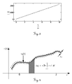
- FIG. 3 shows the phase of an interferogram recorded by a quadrature receiver.
- This received intensity represents the basis of the signal processing.
- the carrier frequency can be obtained directly by a Fourier decomposition so that the distance to be determined can be calculated directly.
- the signals are distorted, so that it offers advantages, the phase ⁇ of the oscillating intensity directly through an optical To measure quadrature receiver.
- the phase thus increases in time dependence - as shown in Fig. 3 - linear.
- FIG. 4 illustrates the frequency response of a monofrequency signal.
- a temporal integration window according to equations (1) and (3) is depicted.
- An interferometer detects the phase change between the emitted signal e (t) and the signal r ( t ) received again after a run over a distance.
- a monofrequency signal or composed of several monofrequency components is used.
- FIG. 5 shows the representation of the frequency response of the virtual interferogram.
- the equivalent measurement data of a length corresponding to the measurement path is generated synthetically.
- An example of the composition of the phases of such a virtual interferogram is shown in the frequency profile in FIG.
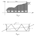
- FIG. 6 schematically shows a first embodiment of the reference element for determining the reference length.
- the interferometer is completely integrated into a Zerodur block 4.
- a first grid 5 is attached, which can be supplemented by a further grid 8 on the exit side.
- the incident beam is split into two beam paths corresponding to zeroth and first order extrema.
- the first beam path 7 of zeroth order propagates directly through the Zerodur block 4, whereas the second beam path 6 of the first order has multiple (total) reflections at the interfaces of the Zerodur block 4.
- the path difference of the beam paths provides in the superposition after exiting a heterodyne signal of known frequency from the physical scale of the Zerodur block.
- the radiation can be recorded by a detector and further processed.
- the Zerodur material a large independence of temperature influences can be achieved. Due to the grids, which can be applied, for example, lithographically, beam guidance can be realized exclusively in the compact and temperature-stable Zerodur block 4. In addition to the two-dimensional separation, a three-dimensional distribution with propagation directions and beam paths in three axes can be realized.
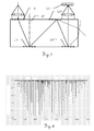
- FIG. 7 schematically illustrates a second embodiment of the reference element with a photodetector, on which a beam path with multiple diffraction is guided.
- This reference element is particularly suitable for narrow wavelength ranges.
- the basis of the realization is a Zerodur block 4 ', on or in the surface of which a first grid 9 and optionally further gratings 10, 10', 10 "are located.
- the angle of the beam guide is the sensitive information.
- the diffraction angle at 1 ⁇ m wavelength in Zerodur is 22.5 °, which corresponds to a grating period of approximately 4.2 ⁇ m.
- the required resolution (1 ppm) determines the width of the illuminated grid section.
- Fig.8 - Fig.9 illustrate the illustration of a gas cell as a third embodiment of the reference element.
- This embodiment uses a natural wavelength reference defined by absorption in a medium, comparable to stabilization in a HeNe laser.
- acetylene gas cells which are commercially available as components can be used for this purpose.
- the application range is 1540 nm with line widths of 0.1 pm.
- 2-3 transitions of high accuracy can be used, so that a very precise determination of the laser wavelength and thus calibration of the reference interferometer can be carried out. Due to the atomic nature of the transitions, temperature-dependent influences can be neglected.
- Figure 8 shows the representation of the absorption spectrum of acetylene
- Figure 9 shows a section of the absorption spectrum of acetylene.
- a gas cell third embodiment of the reference element is illustrated within a complete fiber optic structure.
- Light from the laser source 12 is passed through an optical isolator 13 to avoid external feedback.
- the light in a first beam splitter 14 is coupled asymmetrically (10 dB coupler) into two interferometers, wherein an output terminates in an end piece 15.
- Both interferometers in turn each have a 3X3 coupler 16, which has a phase shift between the effect two detectors, each forming one of the two associated quadrature receiver 17.
- the gas cell 18 is arranged.
- Faraday mirrors 19-19 in the two reference interferometers generate an orthogonally polarized reflected wave with 100% modulation depth in the superimposition. By performing with fibers, good overlap of the radiation is achieved without alignment requirements.
- the singlemode characteristic allows the emission of planar wavefronts via a transmission optics 21 for measuring a target 22. Two photodiodes 20 'are used for monitoring.
Landscapes
- Physics & Mathematics (AREA)
- General Physics & Mathematics (AREA)
- Instruments For Measurement Of Length By Optical Means (AREA)
- Length Measuring Devices By Optical Means (AREA)
- Optical Radar Systems And Details Thereof (AREA)
Priority Applications (8)
| Application Number | Priority Date | Filing Date | Title |
|---|---|---|---|
| EP05101373A EP1696201A1 (fr) | 2005-02-23 | 2005-02-23 | Compensation du bruit de phase pour un interféromètre de mesure d'une distance absolue |
| AU2006217996A AU2006217996B2 (en) | 2005-02-23 | 2006-02-09 | Phase noise compensation for interferometric absolute distance measuring |
| CN200680005923XA CN101128717B (zh) | 2005-02-23 | 2006-02-09 | 用于干涉仪绝对距离测量的相位噪声补偿 |
| US11/816,825 US7619719B2 (en) | 2005-02-23 | 2006-02-09 | Phase noise compensation for interferometric absolute rangefinders |
| PCT/EP2006/050797 WO2006089845A1 (fr) | 2005-02-23 | 2006-02-09 | Compensation du bruit de phase pour mesure de distance absolue par interferometrie |
| EP06708141.4A EP1851504B1 (fr) | 2005-02-23 | 2006-02-09 | Compensation du bruit de phase pour un interféromètre de mesure d'une distance absolue |
| CA2599128A CA2599128C (fr) | 2005-02-23 | 2006-02-09 | Compensation du bruit de phase pour mesure de distance absolue par interferometrie |
| JP2007556586A JP5108534B2 (ja) | 2005-02-23 | 2006-02-09 | 干渉法絶対距離計の位相ノイズ補正 |
Applications Claiming Priority (1)
| Application Number | Priority Date | Filing Date | Title |
|---|---|---|---|
| EP05101373A EP1696201A1 (fr) | 2005-02-23 | 2005-02-23 | Compensation du bruit de phase pour un interféromètre de mesure d'une distance absolue |
Publications (1)
| Publication Number | Publication Date |
|---|---|
| EP1696201A1 true EP1696201A1 (fr) | 2006-08-30 |
Family
ID=34938800
Family Applications (2)
| Application Number | Title | Priority Date | Filing Date |
|---|---|---|---|
| EP05101373A Withdrawn EP1696201A1 (fr) | 2005-02-23 | 2005-02-23 | Compensation du bruit de phase pour un interféromètre de mesure d'une distance absolue |
| EP06708141.4A Expired - Lifetime EP1851504B1 (fr) | 2005-02-23 | 2006-02-09 | Compensation du bruit de phase pour un interféromètre de mesure d'une distance absolue |
Family Applications After (1)
| Application Number | Title | Priority Date | Filing Date |
|---|---|---|---|
| EP06708141.4A Expired - Lifetime EP1851504B1 (fr) | 2005-02-23 | 2006-02-09 | Compensation du bruit de phase pour un interféromètre de mesure d'une distance absolue |
Country Status (7)
| Country | Link |
|---|---|
| US (1) | US7619719B2 (fr) |
| EP (2) | EP1696201A1 (fr) |
| JP (1) | JP5108534B2 (fr) |
| CN (1) | CN101128717B (fr) |
| AU (1) | AU2006217996B2 (fr) |
| CA (1) | CA2599128C (fr) |
| WO (1) | WO2006089845A1 (fr) |
Cited By (6)
| Publication number | Priority date | Publication date | Assignee | Title |
|---|---|---|---|---|
| EP2128560A1 (fr) | 2008-05-28 | 2009-12-02 | Leica Geosystems AG | Procédé de mesure de distance interférométrique doté d'une double puce spectrale séparable et dispositif correspondant |
| EP2128561A1 (fr) | 2008-05-28 | 2009-12-02 | Leica Geosystems AG | Procédé de mesure de distance interférométrique doté d'un signal de Chirp décalé et dispositif correspondant |
| WO2012041586A1 (fr) * | 2010-09-29 | 2012-04-05 | Carl Zeiss Ag | Dispositif et procédé pour mesurer la distance d'un objet à un point de référence |
| EP2816315A1 (fr) * | 2013-06-18 | 2014-12-24 | Hexagon Technology Center GmbH | Détermination interférométrique de changement de distance à l'aide d'une diode laser, de détection de largeur de bande élevée et de traitement rapide de signal |
| DE102015110362A1 (de) * | 2015-06-26 | 2016-12-29 | n-hands GmbH & Co. KG | Verfahren und Vorrichtung zur interferometrischen Absolutmessung einer Entfernung |
| CN118673567A (zh) * | 2024-08-12 | 2024-09-20 | 山西智绘沧穹科技有限公司 | 基于智能移动终端的地理信息监测系统 |
Families Citing this family (16)
| Publication number | Priority date | Publication date | Assignee | Title |
|---|---|---|---|---|
| KR101418832B1 (ko) | 2009-12-14 | 2014-08-13 | 라이카 게오시스템스 아게 | 간섭 거리 측정기에서의 스페클 경감 방법 및 대응하는 거리 측정기 |
| EP2541193A1 (fr) | 2011-06-27 | 2013-01-02 | Hexagon Technology Center GmbH | Procédé de mesure d'éloignement interférométrique pour la mesure de surfaces et un tel appareil de mesure |
| JP5868132B2 (ja) * | 2011-11-14 | 2016-02-24 | キヤノン株式会社 | 撮像装置および画像処理方法 |
| DE102012217282B4 (de) * | 2012-09-25 | 2023-03-02 | Trimble Jena Gmbh | Verfahren und Vorrichtung zur Zuordnung von Messpunkten zu einem Satz von Festpunkten |
| CN103487403B (zh) * | 2013-10-14 | 2015-09-02 | 北京信息科技大学 | 带有参考腔补偿的双波长组合光纤激光器气体检测系统 |
| EP3234500A4 (fr) | 2014-12-19 | 2018-07-04 | University of Utah Research Foundation | Système d'interférométrie et procédés associés |
| EP3329250B1 (fr) * | 2015-07-30 | 2018-12-26 | Koninklijke Philips N.V. | Capteur laser pour détection de taille de particules |
| US11162781B2 (en) | 2016-06-23 | 2021-11-02 | University Of Utah Research Foundation | Interferometry systems and methods |
| US10514250B2 (en) | 2016-06-23 | 2019-12-24 | University Of Utah Research Foundation | Interferometry system and associated methods |
| WO2018160240A2 (fr) * | 2016-11-30 | 2018-09-07 | Blackmore Sensors and Analytics Inc. | Procédé et système de détection doppler et de correction doppler de détection de plage compressée optique |
| CN107741591A (zh) * | 2017-09-21 | 2018-02-27 | 深圳市盛路物联通讯技术有限公司 | 一种干涉测距方法及系统 |
| CN111048978B (zh) * | 2018-10-12 | 2021-04-20 | 华为技术有限公司 | 一种多波长激光器 |
| CA3091463A1 (fr) | 2019-08-29 | 2021-02-28 | Institut National De La Recherche Scientifique | Systeme et methode de stabilisation d'interferometres optiques multivoies |
| CN111445400B (zh) * | 2020-03-13 | 2023-03-17 | 五邑大学 | 存在投影盲区去除绝对相位噪声方法、装置及存储介质 |
| CN116819431B (zh) * | 2023-08-31 | 2023-12-08 | 杭州岸达科技有限公司 | 基于反常相模激励的相位干涉仪测向方法 |
| CN121977683B (zh) * | 2026-04-03 | 2026-06-09 | 齐鲁工业大学(山东省科学院) | 一种神经网络辅助三倍混频pgc差分解调的低频振动信号检测方法 |
Citations (8)
| Publication number | Priority date | Publication date | Assignee | Title |
|---|---|---|---|---|
| EP0260894A1 (fr) * | 1986-09-12 | 1988-03-23 | Cogent Limited | Système de mesure à fibres optiques |
| US5371587A (en) * | 1992-05-06 | 1994-12-06 | The Boeing Company | Chirped synthetic wavelength laser radar |
| EP0646767A2 (fr) * | 1993-10-05 | 1995-04-05 | Renishaw plc | Dispositif de mesure de distance par interférométrie |
| DE19522262A1 (de) * | 1995-06-20 | 1997-01-09 | Zeiss Carl Jena Gmbh | Heterodyn-Interferometer-Anordnung mit durchstimmbaren Lasern |
| WO1998038475A1 (fr) * | 1997-02-25 | 1998-09-03 | Aberlink Technology Limited | Appareil permettant d'etalonner avec precision un intergerometre de mesure de la longueur |
| US20030095261A1 (en) * | 2001-11-16 | 2003-05-22 | Shijie Gu | Tuning and temperature compensation of the air-gap etalon for dense wavelength-division multiplexing application |
| US20030107743A1 (en) * | 2001-12-06 | 2003-06-12 | Van Wiggeren Gregory D. | Phase noise compensation in an interferometric system |
| US20040130728A1 (en) * | 2002-03-29 | 2004-07-08 | Degertekin Fahrettin Levent | Highly-sensitive displacement-measuring optical device |
Family Cites Families (11)
| Publication number | Priority date | Publication date | Assignee | Title |
|---|---|---|---|---|
| US4830486A (en) | 1984-03-16 | 1989-05-16 | Goodwin Frank E | Frequency modulated lasar radar |
| US4697926A (en) * | 1985-02-08 | 1987-10-06 | The Board Of Trustees Of The Leland Stanford Junior University | Coherent distributed sensor and method using short coherence length sources |
| JP2764630B2 (ja) * | 1990-03-20 | 1998-06-11 | 横河電機株式会社 | アブソリュート測長器 |
| JP2725434B2 (ja) * | 1990-03-30 | 1998-03-11 | 横河電機株式会社 | Fmヘテロダイン法を用いたアブソリュート測長方法およびアブソリュート測長器 |
| DE4316348A1 (de) * | 1993-05-15 | 1994-11-17 | Wild Heerbrugg Ag | Vorrichtung zur Distanzmessung |
| CN1099128A (zh) * | 1994-03-04 | 1995-02-22 | 清华大学 | 用双波长激光进行外差干涉测量绝对距离系统 |
| DE19542490C1 (de) * | 1995-11-15 | 1997-06-05 | Leica Ag | Elektro-optisches Meßgerät für absolute Distanzen |
| US6360609B1 (en) * | 2000-02-23 | 2002-03-26 | Massachusetts Institute Of Technology | Method and system for interpreting and utilizing multimode dispersive acoustic guided waves |
| CN1346965A (zh) * | 2001-10-15 | 2002-05-01 | 天津大学 | 一种光纤干涉测量距离的方法及测量设备 |
| US7009691B2 (en) * | 2002-05-29 | 2006-03-07 | Agilent Technologies, Inc. | System and method for removing the relative phase uncertainty in device characterizations performed with a polarimeter |
| EP1707982A1 (fr) * | 2005-03-31 | 2006-10-04 | AGELLIS Group AB | Méthode pour analyser une substance dans un récipient |
-
2005
- 2005-02-23 EP EP05101373A patent/EP1696201A1/fr not_active Withdrawn
-
2006
- 2006-02-09 JP JP2007556586A patent/JP5108534B2/ja not_active Expired - Fee Related
- 2006-02-09 CA CA2599128A patent/CA2599128C/fr not_active Expired - Fee Related
- 2006-02-09 EP EP06708141.4A patent/EP1851504B1/fr not_active Expired - Lifetime
- 2006-02-09 AU AU2006217996A patent/AU2006217996B2/en not_active Ceased
- 2006-02-09 US US11/816,825 patent/US7619719B2/en not_active Expired - Lifetime
- 2006-02-09 CN CN200680005923XA patent/CN101128717B/zh not_active Expired - Lifetime
- 2006-02-09 WO PCT/EP2006/050797 patent/WO2006089845A1/fr not_active Ceased
Patent Citations (8)
| Publication number | Priority date | Publication date | Assignee | Title |
|---|---|---|---|---|
| EP0260894A1 (fr) * | 1986-09-12 | 1988-03-23 | Cogent Limited | Système de mesure à fibres optiques |
| US5371587A (en) * | 1992-05-06 | 1994-12-06 | The Boeing Company | Chirped synthetic wavelength laser radar |
| EP0646767A2 (fr) * | 1993-10-05 | 1995-04-05 | Renishaw plc | Dispositif de mesure de distance par interférométrie |
| DE19522262A1 (de) * | 1995-06-20 | 1997-01-09 | Zeiss Carl Jena Gmbh | Heterodyn-Interferometer-Anordnung mit durchstimmbaren Lasern |
| WO1998038475A1 (fr) * | 1997-02-25 | 1998-09-03 | Aberlink Technology Limited | Appareil permettant d'etalonner avec precision un intergerometre de mesure de la longueur |
| US20030095261A1 (en) * | 2001-11-16 | 2003-05-22 | Shijie Gu | Tuning and temperature compensation of the air-gap etalon for dense wavelength-division multiplexing application |
| US20030107743A1 (en) * | 2001-12-06 | 2003-06-12 | Van Wiggeren Gregory D. | Phase noise compensation in an interferometric system |
| US20040130728A1 (en) * | 2002-03-29 | 2004-07-08 | Degertekin Fahrettin Levent | Highly-sensitive displacement-measuring optical device |
Cited By (9)
| Publication number | Priority date | Publication date | Assignee | Title |
|---|---|---|---|---|
| EP2128560A1 (fr) | 2008-05-28 | 2009-12-02 | Leica Geosystems AG | Procédé de mesure de distance interférométrique doté d'une double puce spectrale séparable et dispositif correspondant |
| EP2128561A1 (fr) | 2008-05-28 | 2009-12-02 | Leica Geosystems AG | Procédé de mesure de distance interférométrique doté d'un signal de Chirp décalé et dispositif correspondant |
| US8654341B2 (en) | 2008-05-28 | 2014-02-18 | Leica Geosystems Ag | Interferometric distance measuring method with spectrally separable double chirp and device |
| WO2012041586A1 (fr) * | 2010-09-29 | 2012-04-05 | Carl Zeiss Ag | Dispositif et procédé pour mesurer la distance d'un objet à un point de référence |
| EP2816315A1 (fr) * | 2013-06-18 | 2014-12-24 | Hexagon Technology Center GmbH | Détermination interférométrique de changement de distance à l'aide d'une diode laser, de détection de largeur de bande élevée et de traitement rapide de signal |
| US9310178B2 (en) | 2013-06-18 | 2016-04-12 | Hexagon Technology Center Gmbh | Interferometric determination of distance change with laser diode, high bandwidth detection and fast signal processing |
| DE102015110362A1 (de) * | 2015-06-26 | 2016-12-29 | n-hands GmbH & Co. KG | Verfahren und Vorrichtung zur interferometrischen Absolutmessung einer Entfernung |
| DE102015110362B4 (de) * | 2015-06-26 | 2018-01-18 | n-hands GmbH & Co. KG | Verfahren und Vorrichtung zur interferometrischen Absolutmessung einer Entfernung |
| CN118673567A (zh) * | 2024-08-12 | 2024-09-20 | 山西智绘沧穹科技有限公司 | 基于智能移动终端的地理信息监测系统 |
Also Published As
| Publication number | Publication date |
|---|---|
| CN101128717A (zh) | 2008-02-20 |
| CA2599128A1 (fr) | 2006-08-31 |
| JP2008532001A (ja) | 2008-08-14 |
| EP1851504B1 (fr) | 2016-11-09 |
| AU2006217996B2 (en) | 2010-08-05 |
| AU2006217996A1 (en) | 2006-08-31 |
| CN101128717B (zh) | 2010-04-14 |
| US20080204698A1 (en) | 2008-08-28 |
| US7619719B2 (en) | 2009-11-17 |
| JP5108534B2 (ja) | 2012-12-26 |
| WO2006089845A1 (fr) | 2006-08-31 |
| CA2599128C (fr) | 2013-07-09 |
| EP1851504A1 (fr) | 2007-11-07 |
Similar Documents
| Publication | Publication Date | Title |
|---|---|---|
| EP1851504B1 (fr) | Compensation du bruit de phase pour un interféromètre de mesure d'une distance absolue | |
| EP2128561B1 (fr) | Procédé de mesure de distance interférométrique doté d'un signal de Chirp décalé et dispositif correspondant | |
| EP2128560B1 (fr) | Procédé de mesure de distance interférométrique doté d'une double puce spectrale séparable et dispositif correspondant | |
| DE69725859T2 (de) | Messen von Effekten des Brechungsindex eines Gases mit unterschiedlicher Vielfach - Interferometrie ( superheterodyn ) | |
| DE69723709T2 (de) | Superheterodyn-interferometer und verfahren zur kompensation des brechungsindexes von luft mittels elektronischer frequenzmultiplikation | |
| DE19601875C2 (de) | Verfahren und Vorrichtung zur Elimination von Störeinflüssen beim FMCW-Radar | |
| DE19743493C2 (de) | Verfahren und Vorrichtung zur Laserfrequenzmessung und -Stabilisierung | |
| EP2223038B1 (fr) | Dispositif d'interférométrie et procédé pour le faire fonctionner | |
| DE102012001754A1 (de) | Mehrskalige Distanzmessung mit Frequenzkämmen | |
| EP3581962A1 (fr) | Procédé de mesure de distance fmcw à deux faisceaux à compensation d'une erreur de mesure de distance dépendante de la vitesse | |
| DE19628200A1 (de) | Vorrichtung und Verfahren zur Durchführung interferometrischer Messungen | |
| DE102014004697B4 (de) | System und Verfahren zur Distanzmessung | |
| DE102021105770A1 (de) | Abstandsmessung mittels eines aktiven optischen Sensorsystems | |
| DE60219550T2 (de) | Verfahren und System zur optischen Spektrumsanalyse mit Korrektur einer ungleichmässigen Abtastrate | |
| DE102004053082A1 (de) | Positionsmesssystem | |
| DE102010062842B4 (de) | Verfahren und Vorrichtung zur Bestimmung der absoluten Position eines Objekts | |
| WO2008003302A1 (fr) | Procédé pour le palpage de motifs d'interférence optiques avec des capteurs linéaires | |
| DE4116039A1 (de) | Interferometrisches verfahren und interferometer zur durchfuehrung desselben | |
| DE4139839A1 (de) | Verfahren und vorrichtung zur bestimmung von schwebungsfrequenzaenderungen zwischen zwei single-mode-lasern sowie zur vermessung von distanzen | |
| EP4050301B1 (fr) | Dispositif de mesure interférometrique de distance | |
| EP0646766A2 (fr) | Procédé et dispositif pour l'interférométrie absolue avec du rayonnement à diode-laser | |
| DE19707773C2 (de) | Vorrichtung und Verfahren zum Bestimmen der Phasendifferenz zwischen interferierenden Strahlen | |
| DE102020215073A1 (de) | Selbstkalibrierendes optronisches Messsystem | |
| EP1064517B1 (fr) | Procede et dispositif de mesure de longueur interferometrique absolue | |
| DE102022120607B4 (de) | Optische Vorrichtung, System und Verfahren zur Dispersionsinterferometrie |
Legal Events
| Date | Code | Title | Description |
|---|---|---|---|
| PUAI | Public reference made under article 153(3) epc to a published international application that has entered the european phase |
Free format text: ORIGINAL CODE: 0009012 |
|
| AK | Designated contracting states |
Kind code of ref document: A1 Designated state(s): AT BE BG CH CY CZ DE DK EE ES FI FR GB GR HU IE IS IT LI LT LU MC NL PL PT RO SE SI SK TR |
|
| AX | Request for extension of the european patent |
Extension state: AL BA HR LV MK YU |
|
| AKX | Designation fees paid | ||
| REG | Reference to a national code |
Ref country code: DE Ref legal event code: 8566 |
|
| STAA | Information on the status of an ep patent application or granted ep patent |
Free format text: STATUS: THE APPLICATION IS DEEMED TO BE WITHDRAWN |
|
| 18D | Application deemed to be withdrawn |
Effective date: 20070302 |