EP1696332A2 - Bus sans fil interne haute vitesse - Google Patents
Bus sans fil interne haute vitesse Download PDFInfo
- Publication number
- EP1696332A2 EP1696332A2 EP06100718A EP06100718A EP1696332A2 EP 1696332 A2 EP1696332 A2 EP 1696332A2 EP 06100718 A EP06100718 A EP 06100718A EP 06100718 A EP06100718 A EP 06100718A EP 1696332 A2 EP1696332 A2 EP 1696332A2
- Authority
- EP
- European Patent Office
- Prior art keywords
- computing device
- resources
- computing
- critical
- computer
- Prior art date
- Legal status (The legal status is an assumption and is not a legal conclusion. Google has not performed a legal analysis and makes no representation as to the accuracy of the status listed.)
- Granted
Links
Images


Classifications
-
- G—PHYSICS
- G06—COMPUTING OR CALCULATING; COUNTING
- G06F—ELECTRIC DIGITAL DATA PROCESSING
- G06F15/00—Digital computers in general; Data processing equipment in general
- G06F15/16—Combinations of two or more digital computers each having at least an arithmetic unit, a program unit and a register, e.g. for a simultaneous processing of several programs
-
- H—ELECTRICITY
- H04—ELECTRIC COMMUNICATION TECHNIQUE
- H04W—WIRELESS COMMUNICATION NETWORKS
- H04W92/00—Interfaces specially adapted for wireless communication networks
- H04W92/16—Interfaces between hierarchically similar devices
- H04W92/18—Interfaces between hierarchically similar devices between terminal devices
-
- G—PHYSICS
- G06—COMPUTING OR CALCULATING; COUNTING
- G06F—ELECTRIC DIGITAL DATA PROCESSING
- G06F13/00—Interconnection of, or transfer of information or other signals between, memories, input/output devices or central processing units
- G06F13/10—Program control for peripheral devices
- G06F13/12—Program control for peripheral devices using hardware independent of the central processor, e.g. channel or peripheral processor
-
- H—ELECTRICITY
- H04—ELECTRIC COMMUNICATION TECHNIQUE
- H04W—WIRELESS COMMUNICATION NETWORKS
- H04W76/00—Connection management
- H04W76/10—Connection setup
-
- H—ELECTRICITY
- H04—ELECTRIC COMMUNICATION TECHNIQUE
- H04W—WIRELESS COMMUNICATION NETWORKS
- H04W8/00—Network data management
- H04W8/005—Discovery of network devices, e.g. terminals
Definitions
- This invention pertains generally to the art and science of connectivity among computing devices. More particularly, the invention relates to a method and system that enables two or more computing devices to be connected together through a high-speed wireless bus.
- the digital revolution ushered in by widely available computing devices is now well under way, and a secondary wave is now occurring.
- the secondary wave involves enhanced interconnectivity of various available computing devices, as users require increased mobility and/or less cluttered experience.
- a traditional desktop PC can provide a great deal of utility.
- the user is typically tethered in place by the size of the machine as well as its various wired connections.
- portable devices by the their nature, often lack sufficient computing power and memory resources to run complex applications in various environments.
- portable devices often cannot be utilized to run customer resource management (CRM) and other business applications that require a great deal of computing resources to perform adequate front-end processing to present rich environments which users customarily expect.
- CRM customer resource management
- Other applications present multimedia environments and/or rely on processor-intensive operations.
- Such applications cannot now be executed by portable devices due to expanded input and output requirements, such as video and/or audio, or multi-monitor usage. Therefore, there is a need to examine new ways for users of portable and other devices to experience such rich application environments.
- Embodiments of the invention solve the shortcomings inherent in prior techniques by enabling connection at least two computing devices through a high-speed wireless link.
- the resources of the devices may be shared so that, when so connected, the devices appear to the user as a single logical computing entity.
- a mobile host computing device is connected to a stationary host computing device using a high-speed wireless link.
- a link may be established with a high-speed wireless bus that connects to a front-side bus of the respective central processing unit (CPU) for each device.
- CPU central processing unit
- This enables extension of certain computing resources, such as one or more of volatile memory resources, non-volatile memory resources, and the host processor.
- the wireless link is invisible to the higher layers of the operating system and the user. In this way, the host appears to the user as a logical host that contains available resources of multiple physical devices.
- FIG. 1 is a schematic diagram of two computing devices within which embodiments of the invention may be implemented
- FIG. 2 is a schematic diagram of alternative embodiment in which multiple computing devices are linked through a hub according to the invention
- FIG. 3 is a schematic diagram illustrating an exemplary generalized computer networking environment suitable for incorporating embodiments of the invention
- FIG. 4 is a hardware schematic diagram illustrating connection of two computing devices through a front-side bus of the respective devices
- FIG. 5 is a schematic diagram conceptually illustrating connection of two computing devices through a high-speed wireless link.
- FIG. 6 illustrates a flow chart corresponding to a process of authorizing and performing a wireless connection according to an embodiment of the invention.
- the invention relates to connectivity between at least two computing devices using a high-speed wireless link.
- the wireless link enables access to available resources of the computing devices, such as one or more of volatile memory resources, non-volatile memory resources, and the host processor.
- the high-speed wireless link is invisible to the higher layers of the operating system and the user. In this way, the host computing device appears to contain available resources of multiple physical devices.
- high-speed connection refers to a connection, preferably a wireless connection, having a sufficient bandwidth to accommodate data transfer rates that enable interface with a processor located on a computing device.
- that term may refer to a wireless connection to a front-side bus of a computing device.
- FIG. 1 illustrates one embodiment of the invention. This embodiment establishes a single logical host computing entity 10 from a stationary host computing device 12 and a mobile host computing device 14.
- the stationary computing device 12 is illustrated as a desktop PC.
- the mobile host 14 is illustrated as a pen-based mobile computing device.
- the computing devices may be implemented in any fashion.
- the mobile host 14 When the devices are located in relatively close proximity, the mobile host 14 establishes a wireless bridge connection with the stationary host 12 through a high-speed wireless link 16.
- the wireless link 16 is preferably achieved through the Ultra Wideband (UWB) wireless communication technology, due to the amount of bandwidth available through this medium.
- UWB Ultra Wideband
- the high-speed wireless link 16 shown in FIG. 1 bridges the front-side or equivalent busses of the respective computing devices.
- one of the devices may access critical resources of the other device, such as its processor, volatile memory, and non-volatile memory.
- the wireless bridge provides a virtual back-plane that enables ready access to the available resources of the computing devices.
- the operating system of one of the host devices determines the available resources of the connected devices. Such available resources are then expanded to the mobile host device 14 to create a logical host having expanded processing power and/or memory capability.
- the operating system for the mobile host performs such tasks as memory management of the expanded logical host, fragmenting the assignment of work between the processors, management of bandwidth issues between the processors and memory resources, and similar tasks.
- the front-side busses and wireless connection appear to the operating system of the mobile host as a single virtual entity.
- the operating system for the mobile host allocates resources by accounting for wireless channel bandwidth considerations.
- the mobile host operating system may optimize scheduling of available resources based on the bandwidth limitations of the wireless channel.
- the operating system may include functionality for balancing the bandwidth limitations of the wireless channel with resource availability. For example, certain tasks may be more efficiently performed by the mobile host processor due to the wireless connection bandwidth.
- the stationary host computer processor may be better equipped to handle processor-intensive tasks, such as generation of bit-mapped images or the like.
- FIG. 2 shows an alternative embodiment of the invention.
- a first computing device shown as a stationary host PC 22, is connected to a mobile host computing device 24.
- a high-speed wireless link 26 is established between the computing devices 22, 24 via a hub 28.
- the hub 28 provides an access point that operates to coordinate the high-speed wireless connection by managing data traffic between the computing devices 22, 24. This arrangement is particularly advantageous when other UWB devices such as wireless monitors, printers and other peripheral equipment exist in proximity to the location of the hub 28.
- the wireless communication bridge is established, the operation is the same as explained above in conjunction with FIG. 1.
- UWB is sometimes alternatively referred to as impulse, baseband or zero-carrier technology.
- UWB is a wireless communications technology that transmits very short ultra-low power radio signals across a wide frequency spectrum.
- UWB receivers can translate the received burst by recognizing a particular pulse sequence sent by the transmitter.
- the FCC has defined UWB to include any signal that occupies more than 500 MHz or that has more than 20% fractional bandwidth, in the 3.1GHz to 10.6 GHz band.
- the bandwidth of a UWB signal is typically about 25% of the center frequency. For example, a "2 GHz" UWB signal may have a bandwidth of 500 MHz.
- the spectrum allowed for UWB is 7500 MHz. This is substantially greater than the spectrum for other technologies currently in use. For example, ISM at 2.4 GHz encompasses an 83.5 MHz spectrum, while U-NI at 5 GHZ takes up 300 MHz (to be increased to 555 MHz).
- the power of a UWB signal is typically low.
- a UWB signal may be on the order of 1000 times lower than that currently used for Wi-Fi RF transmissions.
- the low power requirement is achieved through the ease in which UWB signals are detected, i.e. the ease with which the signal may be extracted from background noise.
- BPSK binary phase-shift keying
- the single band approach proposes use of the entire 7.5 GHz spectrum as one carrier.
- the multi-band approach segments the 7.5 GHz into equal channels.
- the basic premise is that multiple frequency bands efficiently utilize the UWB spectrum by transmitting multiple UWB signals at the same time. The signals do not interfere with each other because they operate at different frequencies within the UWB spectrum. Each of these signals can be transmitted simultaneously to achieve a very high data rate or can be used as a means of multiple access to allow multiple users to communicate at the same time.
- Several standard digital modulation techniques can be on each individual UWB signal. The output of the modulated UWB signals can be added together before transmission.
- a multi-band UWB system design has a number of advantages including: more scalable and adaptive than single band designs; better co-existence characteristics with systems such as 802.11 la; and lower risk implementations because it leverages more traditional radio design techniques. These advantages can be retained while maintaining similar complexity and power consumption levels as single band designs.
- an advantage of the multi-band approach is that, for example, low bit rate systems can use few bands, high bit rate systems can use many bands.
- Another advantage is to be potentially adaptive to different radio regulations worldwide, in the event that they do not have the same harmonized spectrum allocations, as happened for the 2.4GHz and 5GHz bands used by WiFi and Bluetooth.
- a receiver can dynamically adjust the in-band interference by removing the affected band, or a transmitter can avoid transmitting in a band already used by another service in close proximity.
- the multi-band technique is based on well known wireless communications scheme, modified for use with the UWB spectrum, the technology presents lower implementation risk. This makes multi-band the best candidate for commercial applications that require standards technology and multiple vendors for high volume adoption.
- Multi-band systems permit adaptive selection of the bands to provide good interference robustness and co-existence properties.
- the system detects the presence of an 802.1 la system, for example, it can avoid the use of the bands centered at 5.35GHz or 5.85GHz.
- This same feature can also be utilized to provision for different spectrum allocations outside of the United States; the bands that share the spectrum with extremely sensitive systems can be avoided.
- Notch filters are not an ideal solution because they either increase the receiver's noise figure or require higher performance Low Noise Amplifiers.
- the problem with notch filters is that they are not adaptive and need to be realized with off-chip dedicated hardware.
- notch filters in most cases distort the receive pulse and require additional complexity to compensate for this effect.
- the invention is illustrated as being implemented in a suitable computing environment. Although not required, the invention will be described in the general context of computer-executable instructions, such as procedures, being executed by a personal computer. Generally, procedures include program modules, routines, functions, programs, objects, components, data structures, etc. that perform particular tasks or implement particular abstract data types. Moreover, those skilled in the art will appreciate that the invention may be practiced in a variety of computer system configurations, including hand-held devices, multi-processor systems, and microprocessor-based or programmable consumer electronics devices. The invention may also be practiced in distributed computing environments where tasks are performed by remote processing devices that are linked through a communications network. In a distributed computing environment, program modules may be located in both local and remote memory storage devices.
- the term computer system may be used to refer to a system of computers such as may be found in a distributed computing environment.
- FIG. 3 illustrates an example of a suitable computing system environment 300 in which the invention may be implemented.
- the computing system environment 300 is only one example of a suitable computing environment and is not intended to suggest any limitation as to the scope of use or functionality of the invention.
- the computing environment 300 be interpreted as having any dependency or requirement relating to any one or combination of components illustrated in the exemplary operating environment 300.
- at least one embodiment of the invention does include each component illustrated in the exemplary operating environment 300, another more typical embodiment of the invention excludes some or all non-essential components, for example, input/output devices other than those required for network communications.
- One example system for implementing the invention includes a general purpose computing device in the form of a computer 310.
- Components of the computer 310 may include, but are not limited to, a processing unit 320, a system memory 330, and a system bus 321 that couples various system components including the system memory to the processing unit 320.
- the system bus 321 may be any of several types of bus structures including a memory bus or memory controller, a peripheral bus, and a local bus using any of a variety of bus architectures.
- the computer 310 typically includes a variety of computer-readable media.
- Computer-readable media can be any available media that can be accessed by the computer 310 and include both volatile and nonvolatile media, and removable and non-removable media.
- Computer-readable media may comprise computer storage media and communication media.
- Computer storage media includes volatile and nonvolatile, removable and non-removable media implemented in any method or technology for storage of information such as computer-readable instructions, data structures, program modules or other data.
- Computer storage media includes, but is not limited to, RAM, ROM, EEPROM, flash memory or other memory technology, optical disk storage, or magnetic storage devices, or any other medium which can be used to store the desired information and which can be accessed by the computer 310.
- Communication media typically embodies computer-readable instructions, data structures, program modules or other data in a modulated data signal such as a carrier wave or other transport mechanism and includes any information delivery media.
- modulated data signal means a signal that has one or more of its characteristics set or changed in such a manner as to encode information in the signal.
- communication media includes wired media such as a wired network or direct-wired connection, and wireless media such as acoustic, RF, infrared and other wireless media. Combinations of the any of the above are included within the scope of computer-readable media.
- the system memory 330 includes computer storage media in the form of volatile and/or nonvolatile memory such as read only memory (ROM) 331 and random access memory (RAM) 332.
- ROM read only memory
- RAM random access memory
- FIG. 3 illustrates operating system 334, application programs 335, other program modules 336 and program data 337.
- the computer 310 may also include other removable and non-removable, volatile and nonvolatile computer storage media.
- FIG. 3 illustrates a hard disk drive 341 that reads from or writes to non-removable, nonvolatile magnetic media, a magnetic disk drive 351 that reads from or writes to a removable, nonvolatile magnetic disk 352, and an optical disk drive 355 that reads from or writes to a removable, nonvolatile optical disk 356 such as a CDROM.
- Other computer storage media that can be used in the exemplary operating environment include, but are not limited to, magnetic tape cassettes, flash memory cards, DVDs, digital video tape, solid state RAM, solid state ROM, and the like.
- the hard disk drive 341 is typically connected to the system bus 321 through a non-removable memory interface such as interface 340, and magnetic disk drive 351 and optical disk drive 355 are typically connected to the system bus 321 by a removable memory interface, such as interface 350.
- the computer system may include interfaces for additional types of removable non-volatile storage devices.
- the computer may have a USB port 353 that can accept a USB flash drive (UFD) 354, or a SD card slot 357 that can accept a Secure Digital (SD) memory card 358.
- UFD USB flash drive
- SD Secure Digital
- a USB flash drive is a flash memory device that is fitted with a USB connector that can be inserted into a USB port on various computing devices.
- a SD memory card is a stamp-sized flash memory device. Both the USB flash drive and SD card offer high storage capacity in a small package and high data transfer rates.
- Other types of removable storage media may also be used for implementing the invention.
- the drives and their associated computer storage media provide storage of computer-readable instructions, data structures, program modules and other data for the computer 310.
- hard disk drive 341 is illustrated as storing an operating system 344, application programs 345, other program modules 346 and program data 347. Note that these components can either be the same as or different from operating system 334, application programs 335, other program modules 336, and program data 337.
- Operating system 344, application programs 345, other program modules 346, and program data 347 are given different numbers herein to illustrate that, at a minimum, they are different copies.
- a user may enter commands and information into the computer 310 through input devices such as a keyboard 362 and pointing device 361, commonly referred to as a mouse, trackball or touch pad. These and other input devices are often connected to the processing unit 320 through a user input interface 360 that is coupled to the system bus, but may be connected by other interface and bus structures, such as a parallel port, game port or a universal serial bus (USB).
- a monitor 391 or other type of display device is also connected to the system bus 321 by way of an interface, such as a video interface 390. The monitor 391 may also be integrated with a touch-screen panel or the like.
- monitor and/or touch screen panel can be physically coupled to a housing in which the computing device 310 is incorporated, such as in a tablet-type personal computer.
- computers such as the computing device 310 may also include other peripheral output devices such as speakers 397 and printer 396, which may be connected through an output peripheral interface 395 or the like.
- the computer 310 preferably operates or is adaptable to operate in a networked environment using logical connections to one or more remote computers, such as a remote computer 380.
- the remote computer 380 may be a personal computer, a server, a router, a peer device or other network node, and typically includes some or all of the elements described above relative to the computer 310, although only a memory storage device 381 has been illustrated in Figure 3.
- the logical connections depicted in FIG. 3 include a LAN 371 and a WAN 373, but may also include other networks.
- the computer 310 may comprise the source machine from which data is being migrated, and the remote computer 380 may comprise the destination machine, e.g., a thin client device.
- source and destination machines need not be initially connected by a network or otherwise, but instead, data may be migrated by way of any media capable of being written by the source platform and read by the destination platform or platforms.
- a medium is a portable flash memory medium.
- the computer 310 When used in a LAN environment, the computer 310 is connectable to the LAN 371 through a network interface or adapter 370.
- the computer 310 may also include a modem 372 or other means for establishing communications over the WAN 373.
- the modem 372 which may be internal or external, may be connected to the system bus 321 by way of the user input interface 360 or other appropriate mechanism.
- program modules depicted relative to the computer 310, or portions thereof, may be stored in the remote memory storage device.
- FIG. 3 illustrates remote application programs 385 as residing on memory device 381. It will be appreciated that the network connections shown are exemplary and other means of establishing a communications link between the computers may be used.
- FIG. 4 is a simplified block diagram of certain hardware components that are typically located on the motherboard of a conventional PC or similar computing device.
- the Stationary Host 12 includes a CPU 410 that is connected with a NorthBridge Integrated Circuit 412 via a front-side bus 414.
- the NorthBridge 412 typically handles mission critical tasks, such as dealing with requests for data transfer to and from a RAM 416 as well as data transfer between the CPU and an accelerated graphics port, or AGP 418.
- the NorthBridge 412 includes a memory controller and associated hardware to efficiently manage the movement of data between the processor, the memory modules and the AGP.
- the front-side bus 414 operates at a relatively high clock speed to enable CPU access to the various resources of the system without remaining idle as data is transferred.
- the front-side bus 414 may operate at speeds of 800 MHz, which translates to a peak data bandwidth requirement of 4.2 GB/sec. For this reason, the currently preferred embodiment of the invention employs UWB technology.
- UWB technology As other high-speed wireless technologies are developed, they may likewise be utilized in the present invention.
- the NorthBridge 412 receives and transmits data with a SouthBridge IC 420 via a high speed link therebetween.
- the SouthBridge functions to provide support for a variety of input and output devices, which typically have differing bus speeds and designs.
- the SouthBridge communicates with Interface Drive Electronics 422 for providing access to mass storage devices.
- the SouthBridge may be coupled with a LAN interface 424. Further, the Southbridge is connected to a Peripheral Component Interconnect (PCI) bus 426 to permit expansion cards to be added to the stationary host.
- PCI Peripheral Component Interconnect
- the SouthBridge 420 may further support audio output 428 as well as serial ports 430.
- the SouthBridge 420 provides an interface to BIOS software 432. However, because it does not perform the critical tasks of the NorthBridge, the SouthBridge does not require the data transfer rates of the NorthBridge.
- the Mobile Host 14 may be similarly configured, as shown in the embodiment of FIG. 4.
- the Mobile Host 14 includes a CPU 450 connected to a NorthBridge IC 452 via a front-side bus 454.
- the NorthBridge 452 likewise provides a high-speed interface to a graphics port 454, and to RAM 456.
- the NorthBridge 452 is connected with a SouthBridge 458 via a high-speed connection.
- the SouthBridge 458 permits various internal and external peripheral components, such as an IDE 460, Firewire port 462 and a USB port 464.
- the SouthBridge 458 is coupled with flash memory in which a BIOS 466 is located.
- the Mobile Host 14 contains fewer peripheral components than that of the Stationary Host. Those skilled in the art will appreciate that any of a number of configurations are possible.
- FIG. 4 While the embodiment described in connection with FIG. 4 utilizes a front-side bus architecture, those skilled in the art will appreciate that the invention may be implemented in conjunction with other board-level architectures. For example, the invention may alternatively be implemented to connect to board architectures that use HyperTransportTM links via a high speed wireless connection.
- at least one of the computing devices is designed with HyperTransport technology operating as a fully integrated front-side bus, such as is generally shown in FIG. 3. In this embodiment, the NorthBridge-SouthBridge structure is eliminated.
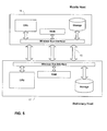
- FIG. 5 illustrates certain features of the invention at a more conceptual level.
- the high-speed wireless bus 16 forms a wireless bridge between the Stationary Host computing device 12 and the Mobile Host computing device 14.
- Such devices expose respective wireless bus interfaces, which permit access to their critical or essential resources.
- the critical resources of the Stationary Host 12 are made available to the Mobile Host 14.
- critical resources refer to any of the Stationary Host processor, RAM and non-volatile storage.
- the critical resources of the Mobile Host 14 are exposed via its wireless bus interface. Because the respective wireless bus interfaces connect directly via the front-side bus of the computing devices, such resources are made available once the connection is established and the credentials of the computing devices are verified.
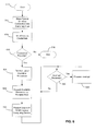
- FIG. 6 illustrates a process for forming a high-speed wireless connection from the standpoint of a mobile host that attempts to establish a connection with a stationary host.
- FIG. 6 focuses on the aspects of an embodiment of the invention and omits certain details that are familiar to those of skill in the art.
- a computing device such as the mobile host computing device 14 shown in FIG. 1, begins at step 610 and proceeds to a step 612 when the computing device 14 detects that one or more other UWB-enabled computing devices are within its transmission range. This detection can be performed by any suitable connection module as will be understood by those skilled in the art.
- the mobile computing device 14 establishes a physical wireless connection with the one or more other detected computing devices, in this case the stationary host computing device 12. Once a wireless connection is established, the mobile host computing device 14 determines whether connectivity via a high-speed wireless bus may occur with the stationary host device in a step 614. For performing this step, the mobile host device 14 issues its credentials.
- the mobile host 14 receives credentials from the stationary host concerning the availability of a connection. Based on the credentials exchanged between the computing devices, the method then proceeds to a step 616 and determines whether a connection may be established. If not, the method ends at a step 618.
- the method proceeds to a next step 620 and receives a list of available resources from the stationary host 12.
- the mobile host 14 expands the available resources to the system. This may include, among other things, allocation of additional volatile memory, extension of a logical disk or non-volatile memory, and use of a second processor.
- the mobile host device 14 presents the user with a single logical computing entity with the combined resources of the mobile host and the stationary host, as shown by a step 624. That is, the mobile host device would appear to the user as including all available resources of both physical devices.
- the operating system of the mobile host device 14 undertakes control of the available resources and performs an assignment of tasks for the resources.
- the resources assigned to created logical entity function under the control of a single operating system.
- the mobile host device 14 may receive interrupt requests from the stationary host 12 as shown at a step 626. If an interrupt request is received, the method advances to a step 628 and services the request. This may include, among other things, reconfiguring the logical unit in the event that certain resources become unavailable. The operating system running on the mobile host handles such requests in a logical fashion so that no perceptible impact is experienced by the user. The method then continues until other interrupt requests are issued. Similarly, the mobile host device may issue interrupt requests to the stationary host device when, for example, a change in resource status occurs.
- a high-speed wireless connection may be established among multiple computing devices.
- multiple parallel wireless communication channels may be used to establish connectivity between computing devices.
Landscapes
- Engineering & Computer Science (AREA)
- Theoretical Computer Science (AREA)
- General Engineering & Computer Science (AREA)
- Computer Hardware Design (AREA)
- Physics & Mathematics (AREA)
- Signal Processing (AREA)
- General Physics & Mathematics (AREA)
- Computer Networks & Wireless Communication (AREA)
- Software Systems (AREA)
- Mobile Radio Communication Systems (AREA)
- Bus Control (AREA)
- Data Exchanges In Wide-Area Networks (AREA)
- Small-Scale Networks (AREA)
Applications Claiming Priority (1)
| Application Number | Priority Date | Filing Date | Title |
|---|---|---|---|
| US11/069,881 US7548749B2 (en) | 2005-02-28 | 2005-02-28 | High-speed internal wireless bus |
Publications (3)
| Publication Number | Publication Date |
|---|---|
| EP1696332A2 true EP1696332A2 (fr) | 2006-08-30 |
| EP1696332A3 EP1696332A3 (fr) | 2006-11-15 |
| EP1696332B1 EP1696332B1 (fr) | 2015-07-08 |
Family
ID=36480942
Family Applications (1)
| Application Number | Title | Priority Date | Filing Date |
|---|---|---|---|
| EP06100718.3A Expired - Lifetime EP1696332B1 (fr) | 2005-02-28 | 2006-01-23 | Bus sans fil interne haute vitesse |
Country Status (5)
| Country | Link |
|---|---|
| US (2) | US7548749B2 (fr) |
| EP (1) | EP1696332B1 (fr) |
| JP (1) | JP4745069B2 (fr) |
| KR (1) | KR101034423B1 (fr) |
| CN (1) | CN100538678C (fr) |
Cited By (1)
| Publication number | Priority date | Publication date | Assignee | Title |
|---|---|---|---|---|
| CN102754068A (zh) * | 2010-02-24 | 2012-10-24 | 惠普发展公司,有限责任合伙企业 | 用于设备的设备驱动程序 |
Families Citing this family (7)
| Publication number | Priority date | Publication date | Assignee | Title |
|---|---|---|---|---|
| US7548749B2 (en) | 2005-02-28 | 2009-06-16 | Microsoft Corporation | High-speed internal wireless bus |
| US20090113211A1 (en) * | 2007-10-31 | 2009-04-30 | Chun-Hung Liu | Processing unit including a wireless module and method thereof |
| KR100980778B1 (ko) | 2007-11-06 | 2010-09-10 | 전자부품연구원 | 자율 리소스 공유를 위한 리소스 컴포저 및 제어 방법 |
| KR101538803B1 (ko) * | 2008-09-09 | 2015-07-22 | 삼성전자주식회사 | 펜 테이블로서 기능 할 수 있는 휴대용 전자장치 및 펜 테이블을 사용하는 컴퓨터 시스템 |
| TWI449356B (zh) * | 2010-02-05 | 2014-08-11 | Htc Corp | 可拆卸的無線通訊模組以及其啟動的方法 |
| US8495271B2 (en) * | 2010-08-04 | 2013-07-23 | International Business Machines Corporation | Injection of I/O messages |
| KR102557193B1 (ko) * | 2016-06-22 | 2023-07-21 | 한국전자통신연구원 | 임베디드 디바이스 제어장치 및 방법 |
Citations (2)
| Publication number | Priority date | Publication date | Assignee | Title |
|---|---|---|---|---|
| US20040148326A1 (en) | 2003-01-24 | 2004-07-29 | Nadgir Neelakanth M. | System and method for unique naming of resources in networked environments |
| EP1494432A2 (fr) | 2003-06-30 | 2005-01-05 | Nokia Corporation | Systeme et procédé pour Weblog et File Sharing dans un environment point-a-point |
Family Cites Families (16)
| Publication number | Priority date | Publication date | Assignee | Title |
|---|---|---|---|---|
| JPH06103243A (ja) * | 1992-09-22 | 1994-04-15 | Hitachi Ltd | 通信機能付きメモリシステム |
| AU2318699A (en) * | 1998-01-13 | 1999-08-02 | Massachusetts Institute Of Technology | Systems and methods for wireless communications |
| US6529743B1 (en) * | 1999-03-29 | 2003-03-04 | 3Com Corporation | Universal wireless telephone to modem adapter |
| JP2001103568A (ja) * | 1999-09-30 | 2001-04-13 | Toshiba Corp | 通信システム、この通信システムに用いられる移動体通信装置、携帯型情報処理装置及びデータ通信方法 |
| US6442661B1 (en) * | 2000-02-29 | 2002-08-27 | Quantum Corporation | Self-tuning memory management for computer systems |
| CN1932788B (zh) * | 2001-01-31 | 2012-07-18 | 株式会社日立制作所 | 数据处理系统和数据处理器 |
| US7149529B2 (en) * | 2001-05-07 | 2006-12-12 | Hewlett-Packard Development Company, L.P. | Method and system for controlling selective wireless communication access |
| JP2002345039A (ja) * | 2001-05-21 | 2002-11-29 | Sony Corp | データ端末機器及びファイル共有方法 |
| US7206559B2 (en) * | 2001-10-16 | 2007-04-17 | Hewlett-Packard Development Company, L.P. | System and method for a mobile computing device to control appliances |
| US7164886B2 (en) * | 2001-10-30 | 2007-01-16 | Texas Instruments Incorporated | Bluetooth transparent bridge |
| US7523209B1 (en) * | 2002-09-04 | 2009-04-21 | Nvidia Corporation | Protocol and interface for source-synchronous digital link |
| US6779069B1 (en) * | 2002-09-04 | 2004-08-17 | Nvidia Corporation | Computer system with source-synchronous digital link |
| US7360067B2 (en) * | 2002-12-12 | 2008-04-15 | International Business Machines Corporation | Method and data processing system for microprocessor communication in a cluster-based multi-processor wireless network |
| US7548749B2 (en) * | 2005-02-28 | 2009-06-16 | Microsoft Corporation | High-speed internal wireless bus |
| US7746349B1 (en) * | 2005-03-16 | 2010-06-29 | Nvidia Corporation | Method and apparatus for display of data |
| US8165111B2 (en) * | 2006-07-25 | 2012-04-24 | PSIMAST, Inc | Telecommunication and computing platforms with serial packet switched integrated memory access technology |
-
2005
- 2005-02-28 US US11/069,881 patent/US7548749B2/en not_active Expired - Fee Related
-
2006
- 2006-01-16 KR KR1020060004337A patent/KR101034423B1/ko not_active Expired - Fee Related
- 2006-01-23 EP EP06100718.3A patent/EP1696332B1/fr not_active Expired - Lifetime
- 2006-01-26 JP JP2006017079A patent/JP4745069B2/ja not_active Expired - Fee Related
- 2006-01-27 CN CNB200610004627XA patent/CN100538678C/zh not_active Expired - Fee Related
-
2007
- 2007-08-29 US US11/847,288 patent/US8005470B2/en active Active
Patent Citations (2)
| Publication number | Priority date | Publication date | Assignee | Title |
|---|---|---|---|---|
| US20040148326A1 (en) | 2003-01-24 | 2004-07-29 | Nadgir Neelakanth M. | System and method for unique naming of resources in networked environments |
| EP1494432A2 (fr) | 2003-06-30 | 2005-01-05 | Nokia Corporation | Systeme et procédé pour Weblog et File Sharing dans un environment point-a-point |
Cited By (2)
| Publication number | Priority date | Publication date | Assignee | Title |
|---|---|---|---|---|
| CN102754068A (zh) * | 2010-02-24 | 2012-10-24 | 惠普发展公司,有限责任合伙企业 | 用于设备的设备驱动程序 |
| US8984539B2 (en) | 2010-02-24 | 2015-03-17 | Hewlett-Packard Development Company, L.P. | Loading a device driver from a device |
Also Published As
| Publication number | Publication date |
|---|---|
| US20060194539A1 (en) | 2006-08-31 |
| KR101034423B1 (ko) | 2011-05-12 |
| US8005470B2 (en) | 2011-08-23 |
| CN1828565A (zh) | 2006-09-06 |
| EP1696332B1 (fr) | 2015-07-08 |
| JP4745069B2 (ja) | 2011-08-10 |
| KR20060095453A (ko) | 2006-08-31 |
| JP2006246443A (ja) | 2006-09-14 |
| US20080102755A1 (en) | 2008-05-01 |
| EP1696332A3 (fr) | 2006-11-15 |
| CN100538678C (zh) | 2009-09-09 |
| US7548749B2 (en) | 2009-06-16 |
Similar Documents
| Publication | Publication Date | Title |
|---|---|---|
| US8005470B2 (en) | High-speed internal wireless bus | |
| US6742052B2 (en) | Wireless system bus | |
| US7389352B2 (en) | System and method for concurrent WLAN and WPAN wireless modes from a single device | |
| KR100904005B1 (ko) | 전기 인터페이스를 통한 접속의 사용을 지원하는 방법 및장치 | |
| AU2007201223B2 (en) | Devices and systems for improved wireless communication | |
| EP1646155B1 (fr) | Systeme et dispositif de communications radio | |
| US20060233191A1 (en) | Systems and methods for managing wireless communication | |
| WO2022083551A1 (fr) | Procédé de commutation de carte d'émulation, dispositif électronique et système de communication | |
| CN105593782A (zh) | 具有协调的功率和数据通信的信息处理系统对接 | |
| KR20150014319A (ko) | 사용자 인터페이스 화면을 제공하는 모바일 디바이스와 화상형성장치, 및 모바일 디바이스 및 화상형성장치에서 사용자 인터페이스 화면을 제공하는 방법 | |
| CN113473645A (zh) | 数据传输方法和装置 | |
| US8082363B2 (en) | Multiplexed communication between host computer and smartphone used as wireless modem | |
| US8045199B2 (en) | Method and system to share an image forming apparatus among a plurality of hosts | |
| US20060061963A1 (en) | Wireless virtual docking | |
| CN101304356A (zh) | 无线通信终端、半导体器件、数据通信方法和无线通信系统 | |
| US9128811B2 (en) | Assigning addresses to devices on an interconnect | |
| KR101313779B1 (ko) | 미지의 서브-채널 이용 가능성을 지닌 ofdm 시스템을위한 핸드쉐이크 방법 및 장치 | |
| JP2004328161A (ja) | 無線通信システムの通信方法 | |
| US7236482B2 (en) | Method for controlling wireless network access through wired network access interface and associated computer system | |
| CN115996109A (zh) | 装置及其通信方法 | |
| CN113383366A (zh) | 远程多路接入系统及其工作方法 | |
| EP4116835B1 (fr) | Procédé de négociation d'horloge à spectre étalé, et dispositif et système d'interconnexion de composants périphériques express | |
| CN113810912A (zh) | 射频控制方法、装置和电子设备 | |
| CN114630437B (zh) | 时隙聚合方法及装置、计算机存储介质、电子设备 | |
| JP7258039B2 (ja) | ユーザーデバイス及び無線通信システムにおいてその伝送の制御方法 |
Legal Events
| Date | Code | Title | Description |
|---|---|---|---|
| PUAI | Public reference made under article 153(3) epc to a published international application that has entered the european phase |
Free format text: ORIGINAL CODE: 0009012 |
|
| AK | Designated contracting states |
Kind code of ref document: A2 Designated state(s): AT BE BG CH CY CZ DE DK EE ES FI FR GB GR HU IE IS IT LI LT LU LV MC NL PL PT RO SE SI SK TR |
|
| AX | Request for extension of the european patent |
Extension state: AL BA HR MK YU |
|
| PUAL | Search report despatched |
Free format text: ORIGINAL CODE: 0009013 |
|
| AK | Designated contracting states |
Kind code of ref document: A3 Designated state(s): AT BE BG CH CY CZ DE DK EE ES FI FR GB GR HU IE IS IT LI LT LU LV MC NL PL PT RO SE SI SK TR |
|
| AX | Request for extension of the european patent |
Extension state: AL BA HR MK YU |
|
| 17P | Request for examination filed |
Effective date: 20070510 |
|
| 17Q | First examination report despatched |
Effective date: 20070606 |
|
| AKX | Designation fees paid |
Designated state(s): AT BE BG CH CY CZ DE DK EE ES FI FR GB GR HU IE IS IT LI LT LU LV MC NL PL PT RO SE SI SK TR |
|
| REG | Reference to a national code |
Ref country code: DE Ref legal event code: R079 Ref document number: 602006045878 Country of ref document: DE Free format text: PREVIOUS MAIN CLASS: G06F0012080000 Ipc: H04W0092180000 |
|
| GRAP | Despatch of communication of intention to grant a patent |
Free format text: ORIGINAL CODE: EPIDOSNIGR1 |
|
| RIC1 | Information provided on ipc code assigned before grant |
Ipc: H04W 8/00 20090101ALN20150204BHEP Ipc: H04W 76/02 20090101ALN20150204BHEP Ipc: H04W 92/18 20090101AFI20150204BHEP |
|
| RAP1 | Party data changed (applicant data changed or rights of an application transferred) |
Owner name: MICROSOFT TECHNOLOGY LICENSING, LLC |
|
| INTG | Intention to grant announced |
Effective date: 20150306 |
|
| GRAS | Grant fee paid |
Free format text: ORIGINAL CODE: EPIDOSNIGR3 |
|
| GRAA | (expected) grant |
Free format text: ORIGINAL CODE: 0009210 |
|
| AK | Designated contracting states |
Kind code of ref document: B1 Designated state(s): AT BE BG CH CY CZ DE DK EE ES FI FR GB GR HU IE IS IT LI LT LU LV MC NL PL PT RO SE SI SK TR |
|
| REG | Reference to a national code |
Ref country code: GB Ref legal event code: FG4D |
|
| REG | Reference to a national code |
Ref country code: AT Ref legal event code: REF Ref document number: 736230 Country of ref document: AT Kind code of ref document: T Effective date: 20150715 Ref country code: CH Ref legal event code: EP |
|
| REG | Reference to a national code |
Ref country code: IE Ref legal event code: FG4D |
|
| REG | Reference to a national code |
Ref country code: DE Ref legal event code: R096 Ref document number: 602006045878 Country of ref document: DE |
|
| REG | Reference to a national code |
Ref country code: AT Ref legal event code: MK05 Ref document number: 736230 Country of ref document: AT Kind code of ref document: T Effective date: 20150708 |
|
| REG | Reference to a national code |
Ref country code: FR Ref legal event code: PLFP Year of fee payment: 11 |
|
| REG | Reference to a national code |
Ref country code: NL Ref legal event code: FP |
|
| REG | Reference to a national code |
Ref country code: LT Ref legal event code: MG4D |
|
| PG25 | Lapsed in a contracting state [announced via postgrant information from national office to epo] |
Ref country code: LV Free format text: LAPSE BECAUSE OF FAILURE TO SUBMIT A TRANSLATION OF THE DESCRIPTION OR TO PAY THE FEE WITHIN THE PRESCRIBED TIME-LIMIT Effective date: 20150708 Ref country code: FI Free format text: LAPSE BECAUSE OF FAILURE TO SUBMIT A TRANSLATION OF THE DESCRIPTION OR TO PAY THE FEE WITHIN THE PRESCRIBED TIME-LIMIT Effective date: 20150708 Ref country code: LT Free format text: LAPSE BECAUSE OF FAILURE TO SUBMIT A TRANSLATION OF THE DESCRIPTION OR TO PAY THE FEE WITHIN THE PRESCRIBED TIME-LIMIT Effective date: 20150708 Ref country code: GR Free format text: LAPSE BECAUSE OF FAILURE TO SUBMIT A TRANSLATION OF THE DESCRIPTION OR TO PAY THE FEE WITHIN THE PRESCRIBED TIME-LIMIT Effective date: 20151009 |
|
| PG25 | Lapsed in a contracting state [announced via postgrant information from national office to epo] |
Ref country code: AT Free format text: LAPSE BECAUSE OF FAILURE TO SUBMIT A TRANSLATION OF THE DESCRIPTION OR TO PAY THE FEE WITHIN THE PRESCRIBED TIME-LIMIT Effective date: 20150708 Ref country code: PT Free format text: LAPSE BECAUSE OF FAILURE TO SUBMIT A TRANSLATION OF THE DESCRIPTION OR TO PAY THE FEE WITHIN THE PRESCRIBED TIME-LIMIT Effective date: 20151109 Ref country code: SE Free format text: LAPSE BECAUSE OF FAILURE TO SUBMIT A TRANSLATION OF THE DESCRIPTION OR TO PAY THE FEE WITHIN THE PRESCRIBED TIME-LIMIT Effective date: 20150708 Ref country code: ES Free format text: LAPSE BECAUSE OF FAILURE TO SUBMIT A TRANSLATION OF THE DESCRIPTION OR TO PAY THE FEE WITHIN THE PRESCRIBED TIME-LIMIT Effective date: 20150708 Ref country code: IS Free format text: LAPSE BECAUSE OF FAILURE TO SUBMIT A TRANSLATION OF THE DESCRIPTION OR TO PAY THE FEE WITHIN THE PRESCRIBED TIME-LIMIT Effective date: 20151108 Ref country code: PL Free format text: LAPSE BECAUSE OF FAILURE TO SUBMIT A TRANSLATION OF THE DESCRIPTION OR TO PAY THE FEE WITHIN THE PRESCRIBED TIME-LIMIT Effective date: 20150708 |
|
| REG | Reference to a national code |
Ref country code: DE Ref legal event code: R097 Ref document number: 602006045878 Country of ref document: DE |
|
| PG25 | Lapsed in a contracting state [announced via postgrant information from national office to epo] |
Ref country code: SK Free format text: LAPSE BECAUSE OF FAILURE TO SUBMIT A TRANSLATION OF THE DESCRIPTION OR TO PAY THE FEE WITHIN THE PRESCRIBED TIME-LIMIT Effective date: 20150708 Ref country code: EE Free format text: LAPSE BECAUSE OF FAILURE TO SUBMIT A TRANSLATION OF THE DESCRIPTION OR TO PAY THE FEE WITHIN THE PRESCRIBED TIME-LIMIT Effective date: 20150708 Ref country code: CZ Free format text: LAPSE BECAUSE OF FAILURE TO SUBMIT A TRANSLATION OF THE DESCRIPTION OR TO PAY THE FEE WITHIN THE PRESCRIBED TIME-LIMIT Effective date: 20150708 Ref country code: DK Free format text: LAPSE BECAUSE OF FAILURE TO SUBMIT A TRANSLATION OF THE DESCRIPTION OR TO PAY THE FEE WITHIN THE PRESCRIBED TIME-LIMIT Effective date: 20150708 Ref country code: IT Free format text: LAPSE BECAUSE OF FAILURE TO SUBMIT A TRANSLATION OF THE DESCRIPTION OR TO PAY THE FEE WITHIN THE PRESCRIBED TIME-LIMIT Effective date: 20150708 |
|
| PLBE | No opposition filed within time limit |
Free format text: ORIGINAL CODE: 0009261 |
|
| STAA | Information on the status of an ep patent application or granted ep patent |
Free format text: STATUS: NO OPPOSITION FILED WITHIN TIME LIMIT |
|
| PG25 | Lapsed in a contracting state [announced via postgrant information from national office to epo] |
Ref country code: BE Free format text: LAPSE BECAUSE OF NON-PAYMENT OF DUE FEES Effective date: 20160131 Ref country code: RO Free format text: LAPSE BECAUSE OF FAILURE TO SUBMIT A TRANSLATION OF THE DESCRIPTION OR TO PAY THE FEE WITHIN THE PRESCRIBED TIME-LIMIT Effective date: 20150708 |
|
| 26N | No opposition filed |
Effective date: 20160411 |
|
| PG25 | Lapsed in a contracting state [announced via postgrant information from national office to epo] |
Ref country code: LU Free format text: LAPSE BECAUSE OF FAILURE TO SUBMIT A TRANSLATION OF THE DESCRIPTION OR TO PAY THE FEE WITHIN THE PRESCRIBED TIME-LIMIT Effective date: 20160123 Ref country code: SI Free format text: LAPSE BECAUSE OF FAILURE TO SUBMIT A TRANSLATION OF THE DESCRIPTION OR TO PAY THE FEE WITHIN THE PRESCRIBED TIME-LIMIT Effective date: 20150708 |
|
| REG | Reference to a national code |
Ref country code: CH Ref legal event code: PL |
|
| PG25 | Lapsed in a contracting state [announced via postgrant information from national office to epo] |
Ref country code: MC Free format text: LAPSE BECAUSE OF FAILURE TO SUBMIT A TRANSLATION OF THE DESCRIPTION OR TO PAY THE FEE WITHIN THE PRESCRIBED TIME-LIMIT Effective date: 20150708 |
|
| PG25 | Lapsed in a contracting state [announced via postgrant information from national office to epo] |
Ref country code: LI Free format text: LAPSE BECAUSE OF NON-PAYMENT OF DUE FEES Effective date: 20160131 Ref country code: CH Free format text: LAPSE BECAUSE OF NON-PAYMENT OF DUE FEES Effective date: 20160131 |
|
| REG | Reference to a national code |
Ref country code: IE Ref legal event code: MM4A |
|
| REG | Reference to a national code |
Ref country code: FR Ref legal event code: PLFP Year of fee payment: 12 |
|
| PG25 | Lapsed in a contracting state [announced via postgrant information from national office to epo] |
Ref country code: BE Free format text: LAPSE BECAUSE OF FAILURE TO SUBMIT A TRANSLATION OF THE DESCRIPTION OR TO PAY THE FEE WITHIN THE PRESCRIBED TIME-LIMIT Effective date: 20150708 |
|
| PG25 | Lapsed in a contracting state [announced via postgrant information from national office to epo] |
Ref country code: IE Free format text: LAPSE BECAUSE OF NON-PAYMENT OF DUE FEES Effective date: 20160123 |
|
| REG | Reference to a national code |
Ref country code: FR Ref legal event code: PLFP Year of fee payment: 13 |
|
| PG25 | Lapsed in a contracting state [announced via postgrant information from national office to epo] |
Ref country code: HU Free format text: LAPSE BECAUSE OF FAILURE TO SUBMIT A TRANSLATION OF THE DESCRIPTION OR TO PAY THE FEE WITHIN THE PRESCRIBED TIME-LIMIT; INVALID AB INITIO Effective date: 20060123 Ref country code: CY Free format text: LAPSE BECAUSE OF FAILURE TO SUBMIT A TRANSLATION OF THE DESCRIPTION OR TO PAY THE FEE WITHIN THE PRESCRIBED TIME-LIMIT Effective date: 20150708 |
|
| PG25 | Lapsed in a contracting state [announced via postgrant information from national office to epo] |
Ref country code: TR Free format text: LAPSE BECAUSE OF FAILURE TO SUBMIT A TRANSLATION OF THE DESCRIPTION OR TO PAY THE FEE WITHIN THE PRESCRIBED TIME-LIMIT Effective date: 20150708 |
|
| PG25 | Lapsed in a contracting state [announced via postgrant information from national office to epo] |
Ref country code: BG Free format text: LAPSE BECAUSE OF FAILURE TO SUBMIT A TRANSLATION OF THE DESCRIPTION OR TO PAY THE FEE WITHIN THE PRESCRIBED TIME-LIMIT Effective date: 20150708 |
|
| PGFP | Annual fee paid to national office [announced via postgrant information from national office to epo] |
Ref country code: FR Payment date: 20191216 Year of fee payment: 15 |
|
| PGFP | Annual fee paid to national office [announced via postgrant information from national office to epo] |
Ref country code: DE Payment date: 20200107 Year of fee payment: 15 Ref country code: GB Payment date: 20200115 Year of fee payment: 15 Ref country code: NL Payment date: 20200130 Year of fee payment: 15 |
|
| REG | Reference to a national code |
Ref country code: DE Ref legal event code: R082 Ref document number: 602006045878 Country of ref document: DE Representative=s name: PAGE, WHITE & FARRER GERMANY LLP, DE |
|
| REG | Reference to a national code |
Ref country code: DE Ref legal event code: R119 Ref document number: 602006045878 Country of ref document: DE |
|
| REG | Reference to a national code |
Ref country code: NL Ref legal event code: MM Effective date: 20210201 |
|
| GBPC | Gb: european patent ceased through non-payment of renewal fee |
Effective date: 20210123 |
|
| PG25 | Lapsed in a contracting state [announced via postgrant information from national office to epo] |
Ref country code: NL Free format text: LAPSE BECAUSE OF NON-PAYMENT OF DUE FEES Effective date: 20210201 Ref country code: FR Free format text: LAPSE BECAUSE OF NON-PAYMENT OF DUE FEES Effective date: 20210131 |
|
| PG25 | Lapsed in a contracting state [announced via postgrant information from national office to epo] |
Ref country code: GB Free format text: LAPSE BECAUSE OF NON-PAYMENT OF DUE FEES Effective date: 20210123 Ref country code: DE Free format text: LAPSE BECAUSE OF NON-PAYMENT OF DUE FEES Effective date: 20210803 |