EP1696397A2 - Procédé et dispositif de surveillance - Google Patents
Procédé et dispositif de surveillance Download PDFInfo
- Publication number
- EP1696397A2 EP1696397A2 EP06250961A EP06250961A EP1696397A2 EP 1696397 A2 EP1696397 A2 EP 1696397A2 EP 06250961 A EP06250961 A EP 06250961A EP 06250961 A EP06250961 A EP 06250961A EP 1696397 A2 EP1696397 A2 EP 1696397A2
- Authority
- EP
- European Patent Office
- Prior art keywords
- operator
- data
- monitoring system
- monitoring
- location
- Prior art date
- Legal status (The legal status is an assumption and is not a legal conclusion. Google has not performed a legal analysis and makes no representation as to the accuracy of the status listed.)
- Withdrawn
Links
Images




Classifications
-
- G—PHYSICS
- G08—SIGNALLING
- G08B—SIGNALLING SYSTEMS, e.g. PERSONAL CALLING SYSTEMS; ORDER TELEGRAPHS; ALARM SYSTEMS
- G08B13/00—Burglar, theft or intruder alarms
- G08B13/18—Actuation by interference with heat, light, or radiation of shorter wavelength; Actuation by intruding sources of heat, light, or radiation of shorter wavelength
- G08B13/189—Actuation by interference with heat, light, or radiation of shorter wavelength; Actuation by intruding sources of heat, light, or radiation of shorter wavelength using passive radiation detection systems
- G08B13/194—Actuation by interference with heat, light, or radiation of shorter wavelength; Actuation by intruding sources of heat, light, or radiation of shorter wavelength using passive radiation detection systems using image scanning and comparing systems
- G08B13/196—Actuation by interference with heat, light, or radiation of shorter wavelength; Actuation by intruding sources of heat, light, or radiation of shorter wavelength using passive radiation detection systems using image scanning and comparing systems using television cameras
- G08B13/19602—Image analysis to detect motion of the intruder, e.g. by frame subtraction
- G08B13/1961—Movement detection not involving frame subtraction, e.g. motion detection on the basis of luminance changes in the image
-
- G—PHYSICS
- G08—SIGNALLING
- G08B—SIGNALLING SYSTEMS, e.g. PERSONAL CALLING SYSTEMS; ORDER TELEGRAPHS; ALARM SYSTEMS
- G08B13/00—Burglar, theft or intruder alarms
- G08B13/18—Actuation by interference with heat, light, or radiation of shorter wavelength; Actuation by intruding sources of heat, light, or radiation of shorter wavelength
- G08B13/189—Actuation by interference with heat, light, or radiation of shorter wavelength; Actuation by intruding sources of heat, light, or radiation of shorter wavelength using passive radiation detection systems
- G08B13/194—Actuation by interference with heat, light, or radiation of shorter wavelength; Actuation by intruding sources of heat, light, or radiation of shorter wavelength using passive radiation detection systems using image scanning and comparing systems
- G08B13/196—Actuation by interference with heat, light, or radiation of shorter wavelength; Actuation by intruding sources of heat, light, or radiation of shorter wavelength using passive radiation detection systems using image scanning and comparing systems using television cameras
- G08B13/19639—Details of the system layout
- G08B13/19645—Multiple cameras, each having view on one of a plurality of scenes, e.g. multiple cameras for multi-room surveillance or for tracking an object by view hand-over
-
- G—PHYSICS
- G08—SIGNALLING
- G08B—SIGNALLING SYSTEMS, e.g. PERSONAL CALLING SYSTEMS; ORDER TELEGRAPHS; ALARM SYSTEMS
- G08B13/00—Burglar, theft or intruder alarms
- G08B13/18—Actuation by interference with heat, light, or radiation of shorter wavelength; Actuation by intruding sources of heat, light, or radiation of shorter wavelength
- G08B13/189—Actuation by interference with heat, light, or radiation of shorter wavelength; Actuation by intruding sources of heat, light, or radiation of shorter wavelength using passive radiation detection systems
- G08B13/194—Actuation by interference with heat, light, or radiation of shorter wavelength; Actuation by intruding sources of heat, light, or radiation of shorter wavelength using passive radiation detection systems using image scanning and comparing systems
- G08B13/196—Actuation by interference with heat, light, or radiation of shorter wavelength; Actuation by intruding sources of heat, light, or radiation of shorter wavelength using passive radiation detection systems using image scanning and comparing systems using television cameras
- G08B13/19678—User interface
- G08B13/19682—Graphic User Interface [GUI] presenting system data to the user, e.g. information on a screen helping a user interacting with an alarm system
-
- G—PHYSICS
- G08—SIGNALLING
- G08B—SIGNALLING SYSTEMS, e.g. PERSONAL CALLING SYSTEMS; ORDER TELEGRAPHS; ALARM SYSTEMS
- G08B13/00—Burglar, theft or intruder alarms
- G08B13/18—Actuation by interference with heat, light, or radiation of shorter wavelength; Actuation by intruding sources of heat, light, or radiation of shorter wavelength
- G08B13/189—Actuation by interference with heat, light, or radiation of shorter wavelength; Actuation by intruding sources of heat, light, or radiation of shorter wavelength using passive radiation detection systems
- G08B13/194—Actuation by interference with heat, light, or radiation of shorter wavelength; Actuation by intruding sources of heat, light, or radiation of shorter wavelength using passive radiation detection systems using image scanning and comparing systems
- G08B13/196—Actuation by interference with heat, light, or radiation of shorter wavelength; Actuation by intruding sources of heat, light, or radiation of shorter wavelength using passive radiation detection systems using image scanning and comparing systems using television cameras
- G08B13/19678—User interface
- G08B13/19691—Signalling events for better perception by user, e.g. indicating alarms by making display brighter, adding text, creating a sound
-
- G—PHYSICS
- G08—SIGNALLING
- G08B—SIGNALLING SYSTEMS, e.g. PERSONAL CALLING SYSTEMS; ORDER TELEGRAPHS; ALARM SYSTEMS
- G08B13/00—Burglar, theft or intruder alarms
- G08B13/18—Actuation by interference with heat, light, or radiation of shorter wavelength; Actuation by intruding sources of heat, light, or radiation of shorter wavelength
- G08B13/189—Actuation by interference with heat, light, or radiation of shorter wavelength; Actuation by intruding sources of heat, light, or radiation of shorter wavelength using passive radiation detection systems
- G08B13/194—Actuation by interference with heat, light, or radiation of shorter wavelength; Actuation by intruding sources of heat, light, or radiation of shorter wavelength using passive radiation detection systems using image scanning and comparing systems
- G08B13/196—Actuation by interference with heat, light, or radiation of shorter wavelength; Actuation by intruding sources of heat, light, or radiation of shorter wavelength using passive radiation detection systems using image scanning and comparing systems using television cameras
- G08B13/19697—Arrangements wherein non-video detectors generate an alarm themselves
-
- H—ELECTRICITY
- H04—ELECTRIC COMMUNICATION TECHNIQUE
- H04N—PICTORIAL COMMUNICATION, e.g. TELEVISION
- H04N7/00—Television systems
- H04N7/18—Closed-circuit television [CCTV] systems, i.e. systems in which the video signal is not broadcast
Definitions
- the present invention relates generally to monitoring systems.
- the present invention also relates generally to methods of operating such systems.
- CMOS complementary metal-oxide-semiconductor
- CCTV closed-circuit television
- video recorders to effectuate video surveillance of a location (e.g., a bank, a warehouse, etc.). Since the cameras, the televisions, and the video recorders in a CCTV system are all generally located proximate to the location or site that is being monitored, today's monitoring systems are limited to local monitoring.
- monitoring systems are generally limited to a single application (e.g., security). Therefore, such systems provide relatively limited benefit when compared to the cost of the components that make up the systems.
- a dedicated operator e.g., a security guard
- This need for a dedicated operator further increases the cost of modem security systems without providing any additional benefit.
- monitoring systems that are capable of performing a plurality of applications. What is also needed is monitoring systems that can provide information to remote locations. What is further needed are monitoring systems that allow for a single or multiple operator to monitor the system intermittently, thereby freeing the operator up to perform additional tasks. In addition, what is needed are methods of operating the above-discussed monitoring systems.
- a monitoring system includes a data collection system, an operator interface, and a checklist system.
- the data collection system is configured to collect data from location.
- the checklist system is configured to receive data from the data collection system, to request an input from an operator at the operator interface, and to process the data using an automated process and the operator input.
- a method of monitoring includes collecting data pertaining to a location in an automated manner.
- the method also includes presenting the data to an operator and requesting an input from an operator.
- the method further includes processing the data using the input from the operator and an automated procedure.
- the monitoring system includes means for collecting data pertaining to a location in an automated manner.
- the monitoring system also includes means for presenting the data to an operator.
- the monitoring system further includes means for requesting an input from an operator.
- the monitoring system also includes means for processing the data using the input from the operator and an automated procedure.
- the monitoring system includes a data collection system configured to collected data from a location.
- the monitoring system also includes a data processing system.
- the monitoring system includes a checklist system configured to receive the data from the data collection system, to request an input from the data processing system, and to process the data using an automated process and the input.
- FIG. 1 is a schematic diagram of a monitoring system according to an embodiment of the present invention.
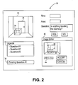
- FIG. 2 illustrates a first representative display that is generated using the checklist system illustrated in FIG. 1 and which appears at the operator interface also illustrated therein.
- FIGS. 3 and 4 each illustrate pop-up menus analogous to the pop-up menu illustrated in FIG. 2 and that show a different view of the same item.
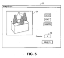
- FIG. 5 illustrates another pop-up menu analogous to the pop-up menu illustrated in FIG. 2, but that allows an operator to monitor the quantity of items in the image.
- FIG. 6 illustrates still another pop-up menu analogous to the pop-up menu illustrated in FIG. 2 but that allows an operator to quantify the number of customers that are waiting in line at a particular register in a supermarket.
- FIG. 7 illustrates a second representative display 68 that is generated using the checklist system 16 illustrated in FIG. 1 and which appears at the operator interface 14 also illustrated therein.
- FIG. 8 illustrates a control panel display according to one embodiment of the present invention.
- FIG 9 illustrates a control panel display according to another embodiment of the present invention.
- FIG. 10 illustrates a control panel display according to yet another embodiment of the present invention.
- FIG. 1 is a schematic diagram of a monitoring system 10 according to an embodiment of the present invention.
- the monitoring system 10 includes a data collection system 12 and an operator interface 14 that are each connected to a checklist system 16.
- the checklist system 16 is connected to a network 18, which itself is connected to an image server 20, a database 22 and a control panel display 24.
- the control panel display 24 is also connected to a supervisory location 26.
- certain embodiments of the monitoring system 10 can be used as security systems, typically by including motion sensors or video monitors that may be used, in conjunction with an operator, to detect motion at a particular location. As will also be discussed below, certain embodiments of the monitoring system 10 can also be used for a variety of other purposes.
- certain embodiments may be used to detect the absence of a particular product at a location in a retail or grocery store (i.e., a "stock-out" condition), movement of people at a particular location, cashier behavior (e.g., adherence to proper checkout procedures, accumulation of customers across all available cashiers, theft), customer behavior (i.e., reaction to various marketing strategies and stimuli), and/or operational procedure compliance (e.g., adherence to guidelines for unloading merchandise from a truck or from a storage area, adherence to guidelines for efficiently placing products on a shelf in a retail environment).
- cashier behavior e.g., adherence to proper checkout procedures, accumulation of customers across all available cashiers, theft
- customer behavior i.e., reaction to various marketing strategies and stimuli
- operational procedure compliance e.g., adherence to guidelines for unloading merchandise from a truck or from a storage area, adherence to guidelines for efficiently placing products on a shelf in a retail environment.
- the data collection system 12 illustrated in FIG. 1 takes the form of a closed circuit television system (CCTV) and includes one or more cameras positioned at one or more locations that are to be monitored.
- the data collection system 12 may include a plurality of cameras located throughout a retail store, a grocery store, a warehouse, or a loading dock.
- the data collection system 12 is capable of taking photographs and/or video footage with one or more of the cameras.
- the data collection system 12 includes types of sensing equipment other than cameras.
- the data collection system 12 may include thermal imaging equipment (e.g., thermal sensors), Radio Frequency Identification (RFID) sensors, fire alarm system sensors (e.g., smoke detectors), and security system sensors (e.g., motion sensors).
- thermal imaging equipment e.g., thermal sensors
- RFID Radio Frequency Identification
- fire alarm system sensors e.g., smoke detectors
- security system sensors e.g., motion sensors
- the data collection system 12 extends across a wide geographical area.
- the data collection system 12 may include cameras or other sensors positioned at a plurality of stores in a regional retail chain or at a plurality of warehouses across one or more countries.
- the operator interface 14 illustrated in FIG. 1, is a location at which a human operator is capable of interacting with the checklist system 16.
- the checklist system 16 as mentioned above, is connected to both the data collection system 12 and the operator interface 14.
- the checklist system 16 controls one or more sensors (e.g., cameras) in the data collection system 12 and can cause a sensor to move to a particular location and/or to begin or cease collecting data at a location.
- the representative checklist system 16 illustrated in FIG. 1 is also connected to the image server 20 and the database 22 through the network 18.
- the image server 20 and/or the database 22 may be located elsewhere in the monitoring system 10 (e.g., within the checklist system 16).
- the checklist system 16 illustrated in FIG. 1 retrieves information from the database 22 and stores data collected using the data collection system 12 in the image server 20 and/or the database 22.
- the checklist system 16 retrieves operational instructions (i.e., instructions that detail how a monitoring procedure should be implemented) that are stored in the database 22.
- the checklist system 16 uses those operational instructions to generate a display menu at the operator interface 14 that provides the operator with an agenda (e.g., an hour-by-hour or minute-by-minute calendar) for monitoring a location.
- An agenda e.g., an hour-by-hour or minute-by-minute calendar
- data collected by the data collection system 12 cannot be adequately processed by currently-available and/or cost-effective data processing systems such as, for example, image recognition systems.
- data processing systems such as, for example, image recognition systems.
- an operator at the operator interface will usually play a role in the operation of the monitoring system 10.
- certain embodiments of the checklist system 16 illustrated in FIG. 1 provide the operator with detailed instructions and/or simply-phrased questions (e.g., "YES”/"NO” questions). This allows for even the most novice of operators to relatively easily participate in the monitoring of one or more locations and/or procedures.
- one or more neural networks and/or image-recognition technologies may be used to further simplify what the operator is requested to do.
- a neural network or image-recognition technology may be used to determine that there are no items on the shelf of a particular grocery store (i.e., that there is a stock-out condition).
- certain embodiments of the present invention do not require operator input, but rather rely completely on neural networks, artificial intelligence and/or sophisticated image processing and recognition to determine whether operational procedures are being adequately followed.
- an operator controls sensors in data collection system 12 to manually scan one or more locations and, when scanning the shelves of a grocery store, can detect a stock-out condition.
- the operator takes an image of the stock-out location, and the checklist system 16 automatically puts an item into the calendar that specifies that the location is to be re-checked, for example, in 20 minutes.
- the sensor in this case, usually a camera
- the sensor is automatically (i.e., without operator control) sent back to the location of the detected stock out and takes another picture of the location.
- the images of 20 minutes ago and the new image are presented to the operator and the operator is requested to make a decision concerning whether a stock-out condition still exists.
- one or more components in the monitoring system 10 are configured to be able to contact communications systems (e.g., a cellular phone systems and text messaging systems).
- communications systems e.g., a cellular phone systems and text messaging systems.
- a text message, a recorded message, and/or an image is forwarded to a senior responsible party that is likely to address the issue immediately (e.g., a manager).
- a senior responsible party that is likely to address the issue immediately (e.g., a manager).
- certain embodiments of the present invention automatically send a sensor to the location where the conditions was detected after a certain period of time has elapsed and the sensor checks whether the condition has been addressed.
- instructions in an agenda or calendar format are generated by the checklist system 16.
- the agenda or calendar is typically generated using information stored in the database 22 and the agenda or calendar may be used to control where a sensor in the monitoring system is located and for how long of a time period the sensor monitors a particular location. This allows the data collection system to monitor the location by, for example, taking a picture or video footage.
- the checklist system 16 applies an appropriate data processing technique (e.g., image processing) and/or filters the data.
- the checklist system 16 then relays the processed and/or filtered data back to the operator and requests that the operator make a decision concerning whether a condition has been met.
- FIG. 2 illustrates a first representative display 28 that is generated using the checklist system 16 illustrated in FIG. 1 and which appears at the operator interface 14 also illustrated therein.
- an image 30 In the upper left corner of the display 28 is located an image 30 that had been captured by a camera in the data collection system 12.
- an agenda 32 also commonly referred to as a calendar
- questions are typically worded so as to guide a human operator sitting before the interface 14 through the steps of a method for monitoring the area shown in the image 30.
- region 34 that displays questions that the operator was unable to answer at the time that they were posed but to which answers are still needed. Often, questions that appear in region 34 are able to be answered and removed from region 34 once a new, possibly sharper, image 30 appears.
- the pop-up menu 40 illustrated in FIG. 2 is an image editor that includes a copy of the above-discussed image 30. Pursuant to receiving instructions to do so from the display 28, the operator drew a rectangle 42 around the box 36 using the drawing tools 44 included in the pop-up menu 40. In alternate embodiments of the present invention, the drawing procedure can be automatically conducted using image recognition. Since the rectangle 42 is accurately drawn around the box 36 to reflect the item that is blocking the doorway 38, the operator may now click on the "ACCEPT" button in the pop-up menu 40 and send the image 30, which includes the rectangle 42, to either the database 22 or image server 20 illustrated in FIG. 1. Otherwise, the operator could have clicked on the "CANCEL” button and re-drawn the rectangle 42.
- FIGS. 3 and 4 each illustrate pop-up menus 39, 41 analogous to the pop-up menu 40 illustrated in FIG. 2 and that show different views 46, 47 of the same item 48.
- the pop-up menus 39, 41 illustrated in FIGS. 3 and 4 may be used, for example, when the question posed in the upper right corner of the display 28 illustrated in FIG. 2 is whether the shelf 48 is fully stocked. Under such circumstances, the operator would click on the "NEXT" button if all of the shelf space visible in FIG. 3 was fully stocked, which would generate the pop-up menu 41 illustrated in FIG. 4. If all of the visible shelf space in FIG.
- FIG. 5 illustrates another pop-up menu 50 analogous to the pop-up menu 40 illustrated in FIG. 2 but that allows an operator to monitor the quantity of items 52 in the image 54.
- an operator can, for example, use a computer mouse to click on every item 52 (i.e., bottle) shown in the image 54.
- a marker is drawn on one of the items and the counter 56 is incremented by one.
- the counter can be decremented by one and a marker may be removed from the image 54 using the "DELETE" button. In alternate embodiments of the present invention, this can be automatically accomplished.
- FIG. 6 illustrates still another pop-up menu 58 analogous to the pop-up menu 40 illustrated in FIG. 2 but that allows an operator to quantify the number of customers 60 that are waiting in line at a particular register in a supermarket.
- a robotic system is included in the data collection system 12 and controlled by the checklist system 16. This robotic system indicates, in the upper right corner of pop-up menu 58, which register is being monitored in the image 62. Also, the time and date of when the image 62 was generated can be automatically collected by the monitoring system 10. Therefore, in the pop-up menu 58, the operator merely clicks or draws circles 64 around the customers waiting in line and a counter 66 is incremented. Using the pop-up menu 58, the operator can also input whether the cashier is open.
- pop-up menu 58 illustrated in FIG. 6 One advantage of using the pop-up menu 58 illustrated in FIG. 6 is that the operator, unlike a fully-automated system image recognition system, is able to distinguish between the people seen in the image 62 who are waiting in line or those who are merely accompanying people who are waiting in line. Also, certain embodiments of the present invention are implemented using pop-up menus that ask very simple questions (e.g., YES/NO questions) so as to prevent operator error, even if the operator is a novice.
- very simple questions e.g., YES/NO questions
- FIG. 7 illustrates a second representative display 68 that is generated using the checklist system 16 illustrated in FIG. 1 and which appears at the operator interface 14 also illustrated therein.
- the display 68 includes an image 70 and a spreadsheet 72.
- the image 70 is of a storage facility 74 (e.g., a collection of storage bins) that includes a plurality of items 76 (e.g., boxes) stored therein.
- the spreadsheet 72 includes a plurality of times of day in the left-most column thereof and a plurality of times that items 76 have been on the shelves of the facility 74 on the top-most row thereof.
- the operator When the display 68 initially pops up on the operator interface 14, the operator is directed to click once on each item 76 viewable in the image 70. As seen in the second cell from the left in the second row from the top of the spreadsheet 72, the operator indicated that six (6) items 76 were viewable in the image 70 generated at 9:00 (i.e., at time zero).
- Display 68 is particularly useful for monitoring perishable goods (e.g., milk and yogurt). Once an item 76 has remained in the storage facility 74 beyond a predetermined amount time, according to certain embodiments of the present invention, a responsible party will be notified that the item is about to become unsuitable for sale.
- perishable goods e.g., milk and yogurt
- control panel display 24 may be generated.
- FIG. 8 illustrates a control panel display 24 according to one embodiment of the present invention.
- a plurality of location indicators are provided (e.g., location #1, location #2, etc.). Each of these location indicators may correspond, for example, to a different loading dock, retail or grocery store, or warehouse.
- each of the location indicators is a set of specific procedures that were monitored using the data collection system 12, the operator interface 14, and the checklist system 16 illustrated in FIG. 1 and discussed above.
- a loading dock is the location #1 indicated in the control panel display 24 illustrated in FIG. 8
- the specific procedures monitored at the loading dock may have included detecting that a truck was present at the loading dock, taking video footage of the truck being unloaded, sending the video to the operator at the operator interface 14, and allowing the operator to make a decision as to whether the procedure for unloading the truck had been complied with or not.
- a display such as, for example, the display 28
- information is forwarded to the database 22 and/or image server 20.
- the information becomes available for viewing at the control panel display 24. This allows someone located at the supervisory location 26 (e.g., the corporate headquarters of a chain of grocery stores) to monitor how close to completion a given procedure is.
- the supervisory location 26 e.g., the corporate headquarters of a chain of grocery stores
- a bar graph shows the compliance percentages of a selected procedure at a selected location over a given time period (selected as monthly in the bottom left area of the control panel display 24 illustrated in FIG. 8).
- the bars shown in the upper right 81 area have differing shading, which indicate the level of compliance over a given period of time (e.g. lower left to upper right line shading (see element numbers 83-91) indicates that there is positive compliance and upper left to lower right line shading (see element numbers 92-96) indicates that there is a negative compliance)
- someone located at the supervisory location 26 can then put their mouse over a portion of the graph, double-click and generate what is on the lower right area of the control panel display 24 illustrated in FIG. 8.
- the present invention enables multiple shots or images in a located be viewed and compared.
- the present additionally enables multiple different locations, either in a single monitored location or in differing geographic locations to be compared and viewed as well.
- FIG. 9 illustrates a control panel display 24 according to another embodiment of the present invention.
- the control panel display 24 illustrated in FIG. 9 there are three portions of the bar graphs for February, March and April of 2001.
- the lower portions of each of these bar graphs indicate the percentage of the time that, pursuant to a shelf being empty of a particular product, the shelf was restocked within 15 minutes.
- the middle portion of each of these bar graphs indicates the percentage of the time that, pursuant to the shelf being empty, the shelf was restocked with the product within between 15 and 30 minutes.
- the upper portion of each of these bar graphs then indicates the percentage of the time that it took longer than 30 minutes to restock the shelf.
- This type of display may be particularly useful to someone located at the supervisory location 26 when it is most desired to restock a shelf within a limited time period (e.g., 15 minutes) but when a true problem exists only after a product has not been restocked on a shelf for a relatively extended time period (e.g., longer than 30 minutes). It is noted that the above selection of months and days is merely used for illustrative purposes and it not intend to limit the present invention. The selected period can be based upon any used defined criteria.
- FIG. 10 illustrates a control panel display 24 according to yet another embodiment of the present invention.
- someone located at the supervisory location 26 can quickly get an idea of how many people, on average, are in a cashier's line at a supermarket over a chosen time period. More specifically, based on the information collected over time using the pop-up menu 58 illustrated in FIG. 6, a ratio of the number of people waiting in a cashier's line relative to how many cashiers are available can be calculated at a number of distinct times and averaged over a chosen time period. Relying on the line graph in the upper right area of the control panel display 24 illustrated in FIG. 10, if the number of people per line exceeds a threshold level (e.g., two people in FIG.
- a threshold level e.g., two people in FIG.
- the monitoring system 10 sends out a message that more cashiers are needed or that there is an excess of cashiers which need to be removed.
- the sending of this message may be done, for example, by text messaging system, the Internet, and/or a telecommunications system to which the monitoring system 10 is operably connected.
- control panel display 24 may also be applied to generate a control panel display that keeps track of the quantity of extraordinary events during a given time period. For example, an operator could record any occurrences of motion being detected at locations where such motion is not expect (e.g., in a warehouse that is supposed to be empty). The same kind of line graph as is illustrated in the upper right area of FIG. 10 could be used to track the average number of such occurrences over a given time period and, if a threshold value it exceeded, the police could automatically be called or the operator could go over to the location to investigate.
Landscapes
- Engineering & Computer Science (AREA)
- Physics & Mathematics (AREA)
- General Physics & Mathematics (AREA)
- Human Computer Interaction (AREA)
- Multimedia (AREA)
- Signal Processing (AREA)
- Computer Vision & Pattern Recognition (AREA)
- Alarm Systems (AREA)
- Testing, Inspecting, Measuring Of Stereoscopic Televisions And Televisions (AREA)
Applications Claiming Priority (1)
| Application Number | Priority Date | Filing Date | Title |
|---|---|---|---|
| US65495405P | 2005-02-23 | 2005-02-23 |
Publications (2)
| Publication Number | Publication Date |
|---|---|
| EP1696397A2 true EP1696397A2 (fr) | 2006-08-30 |
| EP1696397A3 EP1696397A3 (fr) | 2007-10-24 |
Family
ID=36580028
Family Applications (1)
| Application Number | Title | Priority Date | Filing Date |
|---|---|---|---|
| EP06250961A Withdrawn EP1696397A3 (fr) | 2005-02-23 | 2006-02-23 | Procédé et dispositif de surveillance |
Country Status (2)
| Country | Link |
|---|---|
| US (1) | US20070260429A1 (fr) |
| EP (1) | EP1696397A3 (fr) |
Cited By (2)
| Publication number | Priority date | Publication date | Assignee | Title |
|---|---|---|---|---|
| EP2209315A1 (fr) * | 2009-01-16 | 2010-07-21 | Genr8 Real Time Video Surveillance Solutions | Procédé et système pour la surveillance de fret |
| EP1940171A3 (fr) * | 2006-12-28 | 2016-03-09 | Canon Kabushiki Kaisha | Appareil de surveillance et son procédé d'enregistrement |
Families Citing this family (13)
| Publication number | Priority date | Publication date | Assignee | Title |
|---|---|---|---|---|
| BRPI0610589A2 (pt) * | 2005-04-13 | 2010-07-06 | Store Eyes Inc | sistema e método para medir conformidade de expositor |
| WO2007117368A2 (fr) * | 2006-04-12 | 2007-10-18 | Store Eyes, Inc. | Procédé et appareil de contrôle automatique de la conformité d'utilisation de présentoirs et d'étagères dans un magasin de détail |
| US8009864B2 (en) * | 2007-08-31 | 2011-08-30 | Accenture Global Services Limited | Determination of inventory conditions based on image processing |
| US8189855B2 (en) * | 2007-08-31 | 2012-05-29 | Accenture Global Services Limited | Planogram extraction based on image processing |
| US8630924B2 (en) * | 2007-08-31 | 2014-01-14 | Accenture Global Services Limited | Detection of stock out conditions based on image processing |
| US7949568B2 (en) * | 2007-08-31 | 2011-05-24 | Accenture Global Services Limited | Determination of product display parameters based on image processing |
| US9135491B2 (en) | 2007-08-31 | 2015-09-15 | Accenture Global Services Limited | Digital point-of-sale analyzer |
| MX2012006159A (es) * | 2009-11-27 | 2012-11-29 | Sentry Technology Corp | Sistema de administracion empresarial y metodo de auditoria empleado por el mismo. |
| US10057508B2 (en) | 2013-06-20 | 2018-08-21 | Excelitas Technologies Corp. | Illumination device with integrated thermal imaging sensor |
| US10227190B2 (en) | 2014-10-08 | 2019-03-12 | Rite-Hite Holding Corporation | Methods and apparatus for monitoring a dock leveler |
| JP6008339B1 (ja) * | 2015-04-28 | 2016-10-19 | パナソニックIpマネジメント株式会社 | 商品モニタリング装置、商品モニタリングシステムおよび商品モニタリング方法 |
| US9531741B1 (en) * | 2015-06-11 | 2016-12-27 | Ssh Communications Security Oyj | Controlling a computer system |
| US10565550B1 (en) * | 2016-09-07 | 2020-02-18 | Target Brands, Inc. | Real time scanning of a retail store |
Family Cites Families (27)
| Publication number | Priority date | Publication date | Assignee | Title |
|---|---|---|---|---|
| US3971000A (en) * | 1974-06-20 | 1976-07-20 | The Foxboro Company | Computer-directed process control system with interactive display functions |
| US4962473A (en) * | 1988-12-09 | 1990-10-09 | Itt Corporation | Emergency action systems including console and security monitoring apparatus |
| US5400246A (en) * | 1989-05-09 | 1995-03-21 | Ansan Industries, Ltd. | Peripheral data acquisition, monitor, and adaptive control system via personal computer |
| WO1992017875A1 (fr) * | 1991-04-08 | 1992-10-15 | Hitachi, Ltd. | Procede et appareil pour traitement d'images ou de donnees, et procede et appareil de controle les mettant en ×uvre |
| CA2057961C (fr) * | 1991-05-06 | 2000-06-13 | Robert Paff | Poste de travail graphique integre a un systeme de securite |
| CA2194749C (fr) * | 1997-01-09 | 2002-01-08 | Thomas George Guertin | Simulateur de systeme de secours pour immeuble |
| US6091771A (en) * | 1997-08-01 | 2000-07-18 | Wells Fargo Alarm Services, Inc. | Workstation for video security system |
| US6385772B1 (en) * | 1998-04-30 | 2002-05-07 | Texas Instruments Incorporated | Monitoring system having wireless remote viewing and control |
| JP4124892B2 (ja) * | 1998-07-24 | 2008-07-23 | キヤノン株式会社 | 通信装置及び通信方法及び記憶媒体 |
| US20030025599A1 (en) * | 2001-05-11 | 2003-02-06 | Monroe David A. | Method and apparatus for collecting, sending, archiving and retrieving motion video and still images and notification of detected events |
| US6466258B1 (en) * | 1999-02-12 | 2002-10-15 | Lockheed Martin Corporation | 911 real time information communication |
| US6421571B1 (en) * | 2000-02-29 | 2002-07-16 | Bently Nevada Corporation | Industrial plant asset management system: apparatus and method |
| DE60106997T2 (de) * | 2000-02-29 | 2005-12-01 | Matsushita Electric Industrial Co., Ltd., Kadoma | Bildaufnahmesystem und fahrzeugmontiertes Sensorsystem |
| WO2002045434A1 (fr) * | 2000-12-01 | 2002-06-06 | Vigilos, Inc. | Systeme et procede de traitement de donnees video par detection de mouvement et champs video subdivises |
| JP4045748B2 (ja) * | 2001-02-26 | 2008-02-13 | 日本電気株式会社 | モニタリングシステムおよびその方法 |
| US6646564B1 (en) * | 2001-03-07 | 2003-11-11 | L'air Liquide Societe Anonyme A Directoire Et Conseil De Surveillance Pour L'etude Et L'exploitation Des Procedes Georges Claude | System and method for remote management of equipment operating parameters |
| US7113090B1 (en) * | 2001-04-24 | 2006-09-26 | Alarm.Com Incorporated | System and method for connecting security systems to a wireless device |
| US6970083B2 (en) * | 2001-10-09 | 2005-11-29 | Objectvideo, Inc. | Video tripwire |
| US6658091B1 (en) * | 2002-02-01 | 2003-12-02 | @Security Broadband Corp. | LIfestyle multimedia security system |
| US6992589B2 (en) * | 2003-01-21 | 2006-01-31 | Marsh Rebecca M | System and method for employee notification and evidence gathering during a robbery |
| US7292723B2 (en) * | 2003-02-26 | 2007-11-06 | Walker Digital, Llc | System for image analysis in a network that is structured with multiple layers and differentially weighted neurons |
| US20040223054A1 (en) * | 2003-05-06 | 2004-11-11 | Rotholtz Ben Aaron | Multi-purpose video surveillance |
| US6952163B2 (en) * | 2003-06-11 | 2005-10-04 | Quantum Magnetics, Inc. | Combined systems user interface for centralized monitoring of a screening checkpoint for passengers and baggage |
| AU2004233453B2 (en) * | 2003-12-03 | 2011-02-17 | Envysion, Inc. | Recording a sequence of images |
| US7373395B2 (en) * | 2004-02-04 | 2008-05-13 | Perseus Wireless, Inc. | Method and system for providing information to remote clients |
| US20050273831A1 (en) * | 2004-06-03 | 2005-12-08 | Juda Slomovich | Video monitoring system |
| US7277018B2 (en) * | 2004-09-17 | 2007-10-02 | Incident Alert Systems, Llc | Computer-enabled, networked, facility emergency notification, management and alarm system |
-
2006
- 2006-02-23 US US11/359,769 patent/US20070260429A1/en not_active Abandoned
- 2006-02-23 EP EP06250961A patent/EP1696397A3/fr not_active Withdrawn
Cited By (2)
| Publication number | Priority date | Publication date | Assignee | Title |
|---|---|---|---|---|
| EP1940171A3 (fr) * | 2006-12-28 | 2016-03-09 | Canon Kabushiki Kaisha | Appareil de surveillance et son procédé d'enregistrement |
| EP2209315A1 (fr) * | 2009-01-16 | 2010-07-21 | Genr8 Real Time Video Surveillance Solutions | Procédé et système pour la surveillance de fret |
Also Published As
| Publication number | Publication date |
|---|---|
| US20070260429A1 (en) | 2007-11-08 |
| EP1696397A3 (fr) | 2007-10-24 |
Similar Documents
| Publication | Publication Date | Title |
|---|---|---|
| US20070260429A1 (en) | Method and apparatus for monitoring | |
| US8325036B1 (en) | In stock analytic monitoring | |
| US8170909B2 (en) | System and method for monitoring retail store performance | |
| US10706386B2 (en) | Machine learning inventory management | |
| US9767428B1 (en) | Activity verification | |
| JP5086260B2 (ja) | 対象追跡と警報 | |
| US6847393B2 (en) | Method and system for monitoring point of sale exceptions | |
| US9934663B2 (en) | Apparatus and method for improved live monitoring and alarm handling in video surveillance systems | |
| US20070058040A1 (en) | Video surveillance using spatial-temporal motion analysis | |
| US7843490B2 (en) | Method and system for image information processing and analysis | |
| US7221367B2 (en) | Queue management system and method | |
| US20180300802A1 (en) | Facility imaging device, facility image collecting device, facility image storage device, facility image output control device, facility operation support device, user terminal device, and facility operation support method | |
| EP1829004B1 (fr) | Systeme et procede de surveillance de systemes de securite | |
| US20060290506A1 (en) | Real-time system for monitoring theft protection | |
| JP2017084295A (ja) | 施設運営支援装置、ユーザ端末装置、および施設運営支援方法 | |
| JP2017084293A (ja) | 施設運営支援装置、ユーザ端末装置、および施設運営支援方法 | |
| US11880795B1 (en) | System and method of managing workflow for observed events | |
| JP6226249B2 (ja) | 施設撮像装置、施設画像収集装置、施設画像蓄積装置、および施設画像出力制御装置 | |
| CN112767116A (zh) | 一种押品状态监测方法及装置 | |
| WO2025169862A1 (fr) | Dispositif de traitement d'informations, système de surveillance de produit, et programme | |
| WO2026078429A1 (fr) | Système et procédé de suivi et de gestion en temps réel dans l'industrie alimentaire | |
| WO2001013639A1 (fr) | Systeme d'archivage et de surveillance a distance utilisant des cameras video | |
| JP2003284045A (ja) | 画像監視システムおよび監視方法 | |
| JP2003216851A (ja) | 防犯カメラを利用した商品予約システム |
Legal Events
| Date | Code | Title | Description |
|---|---|---|---|
| PUAI | Public reference made under article 153(3) epc to a published international application that has entered the european phase |
Free format text: ORIGINAL CODE: 0009012 |
|
| AK | Designated contracting states |
Kind code of ref document: A2 Designated state(s): AT BE BG CH CY CZ DE DK EE ES FI FR GB GR HU IE IS IT LI LT LU LV MC NL PL PT RO SE SI SK TR |
|
| AX | Request for extension of the european patent |
Extension state: AL BA HR MK YU |
|
| PUAL | Search report despatched |
Free format text: ORIGINAL CODE: 0009013 |
|
| AK | Designated contracting states |
Kind code of ref document: A3 Designated state(s): AT BE BG CH CY CZ DE DK EE ES FI FR GB GR HU IE IS IT LI LT LU LV MC NL PL PT RO SE SI SK TR |
|
| AX | Request for extension of the european patent |
Extension state: AL BA HR MK YU |
|
| RIC1 | Information provided on ipc code assigned before grant |
Ipc: H04N 7/18 20060101ALI20070914BHEP Ipc: G08B 15/00 20060101ALI20070914BHEP Ipc: G08B 13/196 20060101AFI20060621BHEP |
|
| 17P | Request for examination filed |
Effective date: 20080424 |
|
| 17Q | First examination report despatched |
Effective date: 20080523 |
|
| AKX | Designation fees paid |
Designated state(s): AT BE BG CH CY CZ DE DK EE ES FI FR GB GR HU IE IS IT LI LT LU LV MC NL PL PT RO SE SI SK TR |
|
| STAA | Information on the status of an ep patent application or granted ep patent |
Free format text: STATUS: THE APPLICATION IS DEEMED TO BE WITHDRAWN |
|
| 18D | Application deemed to be withdrawn |
Effective date: 20081203 |