EP1696603A1 - Systeme de communication et procede de communication l'utilisant - Google Patents
Systeme de communication et procede de communication l'utilisant Download PDFInfo
- Publication number
- EP1696603A1 EP1696603A1 EP04819467A EP04819467A EP1696603A1 EP 1696603 A1 EP1696603 A1 EP 1696603A1 EP 04819467 A EP04819467 A EP 04819467A EP 04819467 A EP04819467 A EP 04819467A EP 1696603 A1 EP1696603 A1 EP 1696603A1
- Authority
- EP
- European Patent Office
- Prior art keywords
- polarized components
- phase difference
- polarization
- optical pulses
- orthogonally polarized
- Prior art date
- Legal status (The legal status is an assumption and is not a legal conclusion. Google has not performed a legal analysis and makes no representation as to the accuracy of the status listed.)
- Withdrawn
Links
Images


Classifications
-
- H—ELECTRICITY
- H04—ELECTRIC COMMUNICATION TECHNIQUE
- H04L—TRANSMISSION OF DIGITAL INFORMATION, e.g. TELEGRAPHIC COMMUNICATION
- H04L9/00—Cryptographic mechanisms or cryptographic arrangements for secret or secure communications; Network security protocols
- H04L9/08—Key distribution or management, e.g. generation, sharing or updating, of cryptographic keys or passwords
- H04L9/0816—Key establishment, i.e. cryptographic processes or cryptographic protocols whereby a shared secret becomes available to two or more parties, for subsequent use
- H04L9/0852—Quantum cryptography
- H04L9/0858—Details about key distillation or coding, e.g. reconciliation, error correction, privacy amplification, polarisation coding or phase coding
Definitions
- the present invention relates to communication systems and communication methods using the same, in particular, to a communication system for performing a quantum cryptographic key distribution to share cryptographic keys through optical fiber communication and a communication method using the same.
- the one-time pad method is an encryption method proved to be unconditionally secure in information theory.
- the one-time pad method is characterized in that cryptographic keys, having the same length as corresponding communication messages, are discarded after being used once.
- Non-patent Document 1 cited below a specific protocol for securely distributing cryptographic keys used in the one-time pad method is suggested.
- quantum cryptography Since physical laws guarantee the security of quantum cryptography, ultimate security independent of the limits of computer performance can be guaranteed.
- 1-bit information is transmitted as a state of a single photon. Hence, a change in the state of the photon caused by an optical fiber, namely a transmission path, markedly reduces the security of quantum cryptography.
- an optical pulse is temporally split into two time-divided optical pulses using an interferometer, having different optical paths, at a second station (i.e., a transmitting side).
- a second station i.e., a transmitting side
- a random number bit composing a cryptographic key
- the transmitted random number bit is regenerated at a first station (i.e., a receiving side) by causing the two time-divided optical pulses to interfere.
- optical-path differences of interferometers used at the second station (i.e., the transmitting side) and the first station (i.e., the receiving side) have to be completely the same.
- the quantum cryptography utilizes the increase in the reception error rate to detect eavesdroppers.
- the increase in reception error rate due to the change in the polarization state at the transmission path lowers eavesdropper detection probability, which results in a decrease in the security of the quantum cryptography.
- the amount of information corresponding to potentially eavesdropped bits in the random number bits groups shared between the first station and the second station is discarded to ascertain the confidentiality of the shared random number bits data.
- the reception error rate determines the amount of information to be discarded. If the reception error rate is high, more information has to be discarded, which decreases the amount of shared random number data, thus reducing the generation rate of cryptographic keys in the quantum cryptography.
- Patent Document 3 which is a simplified configuration of that described in Patent Document 1, or Non-patent Document 2 cited below, a quantum cryptographic device for compensating the change in the polarization direction using a Faraday mirror has been invented.
- a receiver first transmits temporally split optical pulses, whose polarization directions are orthogonal, to a sender.
- the sender reverses the traveling direction of the transmitted light using the Faraday mirror.
- the sender produces a phase difference between the time-divided optical pulses with a phase modulator after rotating their polarization directions by 90 degrees, and then transmits them back to the receiver.
- Patent Document 2 Japanese Patent No. 2951408 Patent Document 3: United States Patent No. 6188768B1
- Non-patent Document 1 Bennet and Brassard, IEEE Int. Conf. on Computers, Systems, and Signal Processing, Bangalore, India, pp. 175 (1984)
- Non-patent Document 2 Ribordy, Gautier, Gisin, Guinnard, and Zbinden, Electronics Letters vol.34, pp.2116-2117 (1998)
- a first disadvantage is that it is difficult to implement a phase modulator used by a sender. This is due to the following reasons.
- the sender produces a phase difference between time-divided optical pulses with a phase modulator.
- This phase modulator has to satisfy the following conditions.
- phase modulators having the modulation bandwidth of 1 GHz or more use lithium niobate or compound semiconductors such as InP. Due to its small loss, the lithium niobate is widely used.
- phase modulators generally have a polarization dependency, and are usually used with particular polarization directions.
- polarization-independent phase modulators there are polarization-independent phase modulators. However, these are designed so that voltage necessary for applying the phase modulations of 0 degrees and 180 degrees is independent of the polarization direction. Thus, this characteristic is not guaranteed at 90 degrees and 270 degrees.
- a second disadvantage is that Faraday mirrors are magneto-optical devices, and unsuitable for future expected integration of optical circuits. This is because the magneto-optical devices cannot be composed of materials used in general integrated optical circuits such as silicon, glass, and lithium niobate. According to a method disclosed in the above-cited Patent Document 3, a phase modulator having the polarization dependency can be used, but a Faraday mirror is still required.
- a third disadvantage is that cryptographic key generation rate changes depending on the rotation angle accuracy of the Faraday mirror and temperature. This is due to the following.
- the accuracy error of the polarization rotation angle of available Faraday mirrors is within ⁇ 3 degrees, regarding those having the best characteristics, within ⁇ 1 degree. If the polarization rotation angle deviates from 90 degrees by 3 degrees, approximately 3% of photons pass through the interferometer without being combined. Corresponding to this, the rate of the accurate cryptographic key generation decreases.
- the polarization rotation angle derived from a Faraday effect depends on temperature. As the temperature of a Faraday element changes, the polarization rotation angle also changes. In general, this temperature dependency is -0.12 degrees/degree Celsius. That is, as the temperature of the element changes by 25 degrees Celsius, the polarization rotation angle caused by the Faraday mirror changes by 3 degrees. This also causes the decrease in the cryptographic key generation rate.
- An object of the present invention is to enable an accurate 90-degree polarization rotation at the second station (i.e., the transmitter) with a reversing configuration for preserving the security against the disturbance of the polarization state at the transmission path, without using the Faraday mirror which causes the decrease in the cryptographic key generation rate.
- an object of the present invention is to provide a communication system capable of employing a polarization-dependent phase modulator and a communication method using the same.
- the communication systems and the communication methods using the same include the first station (i.e., the receiver), the transmission path, and the second station (i.e., the transmitter).
- the first station has means for emitting the time-divided optical pulses into the transmission path and measuring the phase difference between the optical pulses returning from the transmission path.
- the transmission path serves as the transmission medium of the light.
- the second station has means for reversing the traveling direction of the optical pulses, means for producing the phase difference, corresponding to the value of the random number bit to be transmitted, between the time-divided optical pulses, means for splitting each entering optical pulse into the orthogonally polarized components and producing the 180-degree phase difference between the orthogonally polarized components, and means for rotating each polarization direction by 90 degrees.
- the second station may further include means for eliminating the polarized component resulting from a deviation from the polarization rotation angle of 90 degrees when combining the orthogonally polarized components, and means for attenuating the intensity of the optical pulses to include no more than 1 photon per bit when reemitting the optical pulses into the transmission path.
- an optical pulse is split into two orthogonally polarized components at a second station (i.e., a transmitter).
- a second station i.e., a transmitter
- polarization directions of light entering a phase modulator are made to be the same and constant.
- the polarization directions of the optical pulses are made to be orthogonal to their originals.
- the phases of the orthogonally polarized components are reversed.
- the polarization directions of the optical signals entering the second station (i.e., the transmitter) and output from the second station are made to be orthogonal without using the Faraday mirror.
- a quantum cryptography system having a constant cryptographic key generation rate independent of a change in environmental temperature and the accuracy of Faraday elements can be provided.
- the second station i.e., the transmitter
- the polarization direction of each polarized component is rotated by 90 degrees.
- a polarized component resulting from a deviation from a polarization rotation angle of 90 degrees is eliminated.
- the entering optical pulse is split into orthogonally polarized components. A 180-degree phase difference is produced between these orthogonally polarized components. Then the polarization direction of each component is rotated by 90 degrees. When the split orthogonally polarized components are combined, the polarized component resulting from the deviation from the polarization rotation angle of 90 degrees is eliminated.
- the 90-degree polarization rotation can be accurately implemented with a reversing configuration for preserving the security against the disturbance of the polarization state at the transmission path but without using Faraday mirrors.
- a quantum cryptography system capable of employing phase modulators having the polarization dependency is provided.
- Fig. 1 is a schematic configuration diagram of a communication system (a quantum cryptography system) according to an embodiment of the present invention.
- a quantum cryptography system of the present invention includes a first station (a receiver) 1, a transmission path 2, and a second station (a transmitter) 3.
- Optical pulses are emitted from the first station 1 into the transmission path 2, modulated at the second station 3, and returned into the transmission path 2. Then, bit values of the optical pulses are measured at the first station 1.
- the first station 1 has means for emitting temporally divided optical pulses into the transmission path 2 and measuring a phase difference between the optical pulses returning from the transmission path 2.
- the time-divided optical pulses After their polarization states are disturbed at the transmission path 2, the time-divided optical pulses, emitted from the first station 1 into the transmission path 2, enter the second station 3.
- each of the optical pulses is split into two orthogonally polarized components.
- One of the two polarized components directly enters a first phase modulator, whereas the other enters a second phase modulator after having its polarization direction rotated by 90 degrees.
- the first phase modulator produces a phase difference between the optical pulses time-divided at the first station 1.
- the second phase modulator produces the same phase difference as the first phase modulator between the other optical pulses.
- the orthogonally polarized components of each optical pulse are modulated to have a phase difference of 180 degrees therebetween.
- an output of the first phase modulator is combined with an output of the second phase modulator.
- the combined optical pulses are attenuated by an attenuator to include no more than 1 photon per bit.
- the polarized light orthogonal to the polarized light that has been emitted from the first station 1, returns to the first station 1.
- the polarization light be expressed by a two-dimensional vector [ Equation 1 ]
- E ⁇ ( E x E y )
- the disturbance of the polarization state is caused by polarization rotation, which can be denoted as [ Equation 2 ]
- R 0 ( ⁇ ) ( cos ⁇ ⁇ sin ⁇ sin ⁇ cos ⁇ )
- the phase difference between the orthogonally polarized components which can be represented as [ Equation 3 ]
- R i ( ⁇ ) ( exp [ i ⁇ / 2 ] 0 0 exp [ ⁇ i ⁇ / 2 ] )
- the polarization state after passing through the transmission path 2 can be generally expressed as [ Equation 4 ]
- a condition for this is that characteristics of the transmission path 2 do not change during a period necessary for the optical pulse to go and return through the transmission path 2. For example, it takes 0.5 ms for the optical pulse to go and return through a 50 km optical fiber. However, it is known that the polarization state in the optical fiber does not change for a few seconds to a few hours. Therefore, the above condition is satisfied.
- Fig. 2 is a configuration diagram of a receiver (a first station) according to an embodiment of the present invention.
- the first station 1 includes a light source 11, a circulator 12, a beam splitter 13, a polarization controller 14, a phase modulator 15, a polarization beam splitter 16, and photon detectors 17 and 18.
- An optical pulse emitted from the light source 11 passes through the circulator 12, and is split into two optical pulses by the beam splitter 13.
- One of the split optical pulses passes through the phase modulator 15, and enters the polarization beam splitter 16.
- the other split optical pulse also enters the other port of the polarization beam splitter 16 with its polarization direction rotated by 90 degrees by the polarization controller 14. After being combined by the polarization beam splitter 16, the split optical pulses are emitted into the transmission path 2 as time-divided optical pulses.
- An optical-path difference from the split of the optical pulse performed by the beam splitter 13 to the combination performed by the polarization beam splitter 16 is configured such that a time difference between the time-divided optical pulses is longer than their optical pulse width and shorter than their pulse intervals.
- the light After passing through the transmission path 2, the light enters the second station 3.
- Fig. 3 is a configuration diagram of a transmitter (the second station) according to an embodiment of the present invention.
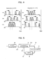
- Fig. 4 is a diagram illustrating a time sequence of optical pulses propagating in the second station according to an embodiment of the present invention.
- the second station 3 includes a polarization beam splitter 31, polarization-maintaining optical fibers 32 and 33, a phase modulator 34, and an optical attenuator 35.
- the entering lights are split into orthogonally polarized components by the polarization beam splitter 31 to produce four optical pulses 301 to 304 as shown in Fig. 4.
- the optical pulses 301, 302, 303, and 304 correspond to one of the polarized components of a first time-divided pulse, the orthogonally polarized component of the first time-divided pulse, one of the polarized components of a second time-divided pulse, and the orthogonally polarized component of the second time-divided pulse, respectively.
- Each of the polarized components is output from a port 312 or 313 of the polarization beam splitter 31.
- the ports 312 and 313 are coupled to the polarization-maintaining optical fibers 32 and 33, respectively, such that electric-field vectors are oriented along slow axes.
- the other ends of the polarization-maintaining optical fibers 32 and 33 are coupled to the ends of the phase modulator 34. Since the electric-field vectors are oriented along the slow axes of the polarization-maintaining optical fibers 32 and 33, the polarization directions of all the optical pulses entering the phase modulator 34 are the same.
- the lengths of the polarization-maintaining optical fibers 32 and 33 are set so that the optical pulses 301 and 303, each corresponding to one of the polarized components, enter the phase modulator 34 a time period T earlier than the optical pulses 302 and 304, each corresponding to the other polarized component.
- the period T is configured to be longer than the optical pulse width and shorter than the interval between the time-divided optical pulses.
- the optical pulses 301 and 303, output from the phase modulator 34 enter the port 313 of the polarization beam splitter 31 through the polarization-maintaining optical fiber 33.
- the optical pulses 302 and 304 output from the phase modulator 34, enter the port 312 of the polarization beam splitter 31 through the polarization-maintaining optical fiber 32.
- the pairs of the optical pulses 301 and 302 as well as 303 and 304 which have passed through the same polarization-maintaining optical fibers 32 and 33 in the opposite direction, enter the polarization beam splitter 31 at the same time, and are combined.
- the combined optical pulses enter the optical attenuator 35 to be attenuated to have an average photon number of a predetermined value between 0.1 and 1. Then, the combined optical pulses propagate through the transmission path 2, and return to the first station 1.
- the electric-field vectors are oriented along the slow axes of the polarization-maintaining optical fibers 32 and 33 in order to rotate the polarization direction by 90 degrees.
- the electric-field vectors may be oriented along any direction as long as the polarization is preserved in the optical fibers.
- the optical pulses may propagate through a non-polarizing single-mode optical fiber or a free space, and be rotated using a polarization controller including a wave plate or the like.
- the optical attenuator 35 is provided in the second station 3. However, the optical attenuator 35 may be provided in the first station 1 so as to adjust the average photon number from the second station 3 to the first station 1 to be a predetermined value between 0.1 and 1.
- phase differences applied to each optical pulse are set as shown in Table 1.
- Table 1 bit value phase(301) phase(302) phase(303) phase(304) 0 0° 180° 0° 180° 0° 180° 90° 270° 1 0° 180° 180° 0° 0° 180° 270° 90°
- phase difference of 0 degrees or 90 degrees is produced between the time-divided optical pulses 301 and 303
- a phase difference of 180 degrees or 270 degrees is produced between the time-divided optical pulses 301 and 303.
- the same phase difference as that between the optical pulses 301 and 303 is produced between the optical pulses 302 and 304, i.e., the orthogonally polarized components of the optical pulses 301 and 303, respectively.
- phase differences of 180 degrees are produced between the optical pulses 301 and 302 as well as the optical pulses 303 and 304.
- Each optical pulse returns to a port different from the port of the polarization beam splitter 31 from which the optical pulse was originally output. Accordingly, each optical pulse having the polarization direction orthogonal to its original is emitted from a port 311 of the polarization beam splitter 31.
- the polarization beam splitter is a general term for an optical system that splits entering light into two orthogonally polarized components in a broad sense.
- a configuration generally used in an optical communication field is described. As shown in Fig. 6(A), this configuration includes two prisms and a dielectric multilayer. By utilizing Brewster's angle of reflection and refraction, this configuration reflects only an s-polarized component 614 orthogonal to an incidence plane, and transmits only a p-polarized component 615 in the incidence plane.
- the optical pulse After entering a port 611 of a polarization beam splitter 61 from the transmission path, the optical pulse is split into the polarized components (i.e., an s-polarized component 616 and a p-polarized component 617), which are then emitted from ports 612 and 613, respectively.
- the polarized components i.e., an s-polarized component 616 and a p-polarized component 617
- each polarized component After being rotated by 90 degrees, each polarized component returns to a port different from that of the polarization beam splitter 61 from which the polarized component was emitted.
- a pure linear polarization state is not obtained because the rotation angle deviates from 90 degrees. More specifically, as shown in Fig. 6(B), when the light is emitted from a port 622, a linear polarization including only an s-polarized component 626 is emitted, and a linear polarization including only a p-polarized component 627 is supposed to enter a port 623 after being rotated by 90 degrees. Nevertheless, due to the deviation of the polarization rotation angle, the entering light also includes an s-polarized component 628.
- the p-polarized component 627 passes through the polarization beam splitter 62 (i.e., a p-polarized component 625), and returns into the transmission path from a port 621, whereas the s-polarized component 628 is reflected by the polarization beam splitter 62 (i.e., an s-polarized component 629), and emitted from a port 624.
- the polarization beam splitter 62 i.e., a p-polarized component 625
- the s-polarized component 628 is reflected by the polarization beam splitter 62 (i.e., an s-polarized component 629), and emitted from a port 624.
- a case where a p-polarization component 637 is emitted from a port 633 of the polarization beam splitter is shown in Fig. 6(C).
- a p-polarized component 636 is also included in the entering light.
- the s-polarized component 638 is reflected by a polarization beam splitter 63 (i.e., an s-polarized component 635), and emitted back into the transmission path from a port 631, whereas the p-polarized component 636 passes through the polarization beam splitter 63 (i.e., a p-polarized component 639), and is emitted from a port 634. Terminating the ports 624 and 634 prevents these light components from returning to the interferometer. If the polarization rotation angle deviates from 90 degrees in the second station, the appropriate modulation cannot be performed in the first station. Accordingly, visibility of the interferometer degrades, which leads to a decrease in the accuracy of cryptographic key generation. However, as described above, use of the polarization beam splitter for splitting and combining the polarized components at the second station can prevent this decrease in the accuracy.
- a description of a polarization beam splitter having four ports is given.
- giving antireflection termination at ports, corresponding to the ports 624 and 634, of a polarization beam splitter having three ports can provide the same advantages.
- the configuration of the polarization beam splitter is not limited to the above configuration.
- a polarization beam splitter having a uniaxial optical crystal or a fiber-fused polarization beam splitter may be used.
- the second station 3 performs three operations, namely, reversing the traveling direction of the light, rotating the polarization direction by 90 degrees, and producing the 180-degree phase difference between the orthogonally polarized components.
- the disturbance at the optical path is offset, thus implementing the stable second station 3.
- the optical pulses After propagating through the transmission path 2 in the opposite direction, the optical pulses reenter the first station 1. According to the polarization direction, the polarization beam splitter 16 directs the optical pulses to the corresponding optical paths. Since the polarization direction of the time-divided optical pulses returning to the first station 1 is orthogonal to that being output from the first station 1, the optical-path difference in the first station 1 is offset. Accordingly, the time-divided optical pulses enter the beam splitter 13 at the same time. At one of the optical paths, the polarization controller 14 rotates the polarization direction by 90 degrees. Thus, the light that has passed through two optical paths interferes.
- a receiver selects a phase modulation of 0 degrees or 90 degrees, and applies the selected modulation to the optical pulses with the phase modulator 15. If the phase modulation of 0 degrees, corresponding to the bit value "0", is performed on the optical pulses 301 and 303 at the second station 3, and the receiver performs the phase modulation of 0 degrees on these optical pulses using the phase modulator 15, photons are observed only at the photon detector 17. If the phase modulation of 180 degrees, corresponding to the bit value "1", is performed on the optical pulses 301 and 303 at the second station 3, and the receiver performs the phase modulation of 0 degrees on these optical pulses using the phase modulator 15, photons are observed only at the photon detector 18.
- phase modulation of 90 degrees corresponding to the bit value "0"
- the receiver performs the phase modulation of 90 degrees on these optical pulses using the phase modulator 15
- photons are observed only at the photon detector 17.
- phase modulation of 270 degrees corresponding to the bit value "1”
- the receiver performs the phase modulation of 90 degrees on these optical pulses using the phase modulator 15, photons are observed only at the photon detector 18.
- the transmitted bit value can be obtained at the first station 1 by detecting the photons at either the photon detector 17 or 18. More specifically, the phase modulation of 0 degrees, 90 degrees, 180 degrees, or 270 degrees is performed at the first station 1.
- a Faraday rotator may be used for producing the 180-degree phase difference between the orthogonally polarized components and rotating each polarized component by 90 degrees.
- a second embodiment having this configuration is shown in Fig. 5.
- phase modulator 34 produces the same phase difference only between optical pulses 303 and 304 among time-divided optical pulses.
- a period of voltage applied to the phase modulator 34 can be doubled, which advantageously simplifies the configuration of a voltage control circuit.
- the present invention can be utilized as a quantum cryptography system for sharing cryptographic keys through optical fiber communication.
Landscapes
- Engineering & Computer Science (AREA)
- Physics & Mathematics (AREA)
- Electromagnetism (AREA)
- Theoretical Computer Science (AREA)
- Computer Security & Cryptography (AREA)
- Computer Networks & Wireless Communication (AREA)
- Signal Processing (AREA)
- Optical Communication System (AREA)
Applications Claiming Priority (3)
| Application Number | Priority Date | Filing Date | Title |
|---|---|---|---|
| JP2003398491 | 2003-11-28 | ||
| JP2004335228 | 2004-11-19 | ||
| PCT/JP2004/017681 WO2005053219A1 (fr) | 2003-11-28 | 2004-11-29 | Systeme de communication et procede de communication l'utilisant |
Publications (2)
| Publication Number | Publication Date |
|---|---|
| EP1696603A1 true EP1696603A1 (fr) | 2006-08-30 |
| EP1696603A4 EP1696603A4 (fr) | 2007-12-12 |
Family
ID=34635623
Family Applications (1)
| Application Number | Title | Priority Date | Filing Date |
|---|---|---|---|
| EP04819467A Withdrawn EP1696603A4 (fr) | 2003-11-28 | 2004-11-29 | Systeme de communication et procede de communication l'utilisant |
Country Status (4)
| Country | Link |
|---|---|
| US (1) | US7974540B2 (fr) |
| EP (1) | EP1696603A4 (fr) |
| JP (1) | JP5142095B2 (fr) |
| WO (1) | WO2005053219A1 (fr) |
Cited By (2)
| Publication number | Priority date | Publication date | Assignee | Title |
|---|---|---|---|---|
| CN101150371B (zh) * | 2006-09-22 | 2012-02-29 | 中国科学院物理研究所 | 一种相位编码偏振检测的量子密钥分配系统 |
| EP2169448A4 (fr) * | 2007-06-15 | 2012-05-30 | Nat Inst Inf & Comm Tech | Dispositif de mise en forme de forme d'onde optique |
Families Citing this family (27)
| Publication number | Priority date | Publication date | Assignee | Title |
|---|---|---|---|---|
| WO2005086409A1 (fr) * | 2004-03-02 | 2005-09-15 | Magiq Technologies, Inc. | Procedes d'etalonnage automatique de modulateurs pour l'echange de cles quantiques |
| JP5384781B2 (ja) | 2005-08-18 | 2014-01-08 | 日本電気株式会社 | 秘匿通信システムおよび共有秘密情報の生成方法 |
| JP2007251678A (ja) * | 2006-03-16 | 2007-09-27 | Sony Corp | 量子暗号通信装置および通信端末における平均光子数設定方法 |
| JP5196093B2 (ja) * | 2006-04-20 | 2013-05-15 | 日本電気株式会社 | 光通信装置およびそれを用いた量子暗号鍵配布システム |
| JP4862128B2 (ja) * | 2006-08-23 | 2012-01-25 | 並木精密宝石株式会社 | 光ファイバループミラー |
| US8494313B2 (en) * | 2009-04-06 | 2013-07-23 | Rockstar Consortium Us Lp | Monitoring eDC polarization inverse filter coefficients to identify real-time physical intrusion into a core or metro optical network |
| MY152705A (en) * | 2010-10-07 | 2014-11-28 | Mimos Berhad | Apparatus for flipping the polarization state of an optical pulse between a transmitter and a receiver in quantum key distribution and method thereof |
| KR102200221B1 (ko) | 2015-05-13 | 2021-01-11 | 한국전자통신연구원 | 다중 출력 양자 난수 발생기 |
| CN107872314B (zh) * | 2016-09-27 | 2020-06-26 | 华为技术有限公司 | 编码装置、光反射器及基于其的量子密钥分发设备及系统 |
| CN108667519B (zh) * | 2017-03-28 | 2024-05-14 | 科大国盾量子技术股份有限公司 | 强度调制装置和方法及其在量子密钥分发系统中的应用 |
| KR101978774B1 (ko) * | 2017-10-20 | 2019-05-15 | 한국전자통신연구원 | 사용자 인증 기반의 양자 직접 통신 방법 및 이를 이용한 장치 |
| CN109842449B (zh) * | 2017-11-24 | 2020-11-10 | 华为技术有限公司 | 生成密钥的设备和方法 |
| US11025416B1 (en) | 2018-03-09 | 2021-06-01 | Wells Fargo Bank, N.A. | Systems and methods for quantum session authentication |
| US10728029B1 (en) | 2018-03-09 | 2020-07-28 | Wells Fargo Bank, N.A. | Systems and methods for multi-server quantum session authentication |
| US10855454B1 (en) | 2018-03-09 | 2020-12-01 | Wells Fargo Bank, N.A. | Systems and methods for quantum session authentication |
| US11343087B1 (en) | 2018-03-09 | 2022-05-24 | Wells Fargo Bank, N.A. | Systems and methods for server-side quantum session authentication |
| US11240013B1 (en) * | 2018-08-20 | 2022-02-01 | Wells Fargo Bank, N.A. | Systems and methods for passive quantum session authentication |
| US11190349B1 (en) | 2018-08-20 | 2021-11-30 | Wells Fargo Bank, N.A. | Systems and methods for providing randomness-as-a-service |
| US10540146B1 (en) | 2018-08-20 | 2020-01-21 | Wells Fargo Bank, N.A. | Systems and methods for single chip quantum random number generation |
| US10855453B1 (en) | 2018-08-20 | 2020-12-01 | Wells Fargo Bank, N.A. | Systems and methods for time-bin quantum session authentication |
| US11095439B1 (en) | 2018-08-20 | 2021-08-17 | Wells Fargo Bank, N.A. | Systems and methods for centralized quantum session authentication |
| CN112104452B (zh) * | 2019-09-04 | 2022-05-03 | 科大国盾量子技术股份有限公司 | 分光组件、用于量子密钥分发的偏振解码装置及接收端 |
| WO2021067631A1 (fr) * | 2019-10-02 | 2021-04-08 | The Research Foundation For The State University Of New York | Dispositifs, systèmes et procédés de réseau quantique |
| WO2022054992A1 (fr) * | 2020-09-11 | 2022-03-17 | 엘지전자 주식회사 | Procédé et dispositif pour corriger une distorsion de polarisation de miroir rotatif de faraday dans un système de distribution de clés quantiques prêt à l'emploi |
| US20240007278A1 (en) * | 2020-10-30 | 2024-01-04 | Lg Electronics Inc. | Method and device for correcting polarization distortion of faraday rotator mirror for quantum key distribution in communication system |
| DE102022121510B3 (de) * | 2022-08-25 | 2023-11-30 | Tesat-Spacecom Gmbh & Co. Kg | Selbstkompensierender Polarisationsmodulator mit direktionalem Phasenschieber, optische Signalübertragungsstrecke und Satellit |
| CN116700676B (zh) * | 2023-08-09 | 2023-09-29 | 北京正道量子科技有限公司 | 一种小型化量子随机数发生器 |
Family Cites Families (29)
| Publication number | Priority date | Publication date | Assignee | Title |
|---|---|---|---|---|
| JP2761141B2 (ja) * | 1992-02-26 | 1998-06-04 | 日本電信電話株式会社 | 偏波回転ミラー |
| US5903388A (en) * | 1992-06-11 | 1999-05-11 | Sedlmayr Steven R | High efficiency electromagnetic beam projector and systems and method for implementation thereof |
| WO1995007584A1 (fr) | 1993-09-09 | 1995-03-16 | British Telecommunications Public Limited Company | Systeme et procede s'appliquant a la cryptographie quantique |
| JPH07175024A (ja) * | 1993-10-29 | 1995-07-14 | Furukawa Electric Co Ltd:The | 光外部変調器 |
| JPH08304203A (ja) * | 1995-05-02 | 1996-11-22 | Hitachi Ltd | 光式圧力検出方法とそのセンサ及び光式圧力センサの波長板、偏光選択装置とビーム分配器、並びに、かかる方法による多点計測光式圧力センサシステムとそのセンシングプローブ |
| DK0923828T3 (da) * | 1996-09-05 | 2004-05-24 | Swisscom Ag | Kvantekryptografiindretning og fremgangsmåde |
| JP3094950B2 (ja) * | 1997-05-28 | 2000-10-03 | 日本電気株式会社 | 光送信装置及び光送信方法 |
| US6188768B1 (en) | 1998-03-31 | 2001-02-13 | International Business Machines Corporation | Autocompensating quantum cryptographic key distribution system based on polarization splitting of light |
| JP4060551B2 (ja) * | 2000-09-07 | 2008-03-12 | 三菱電機株式会社 | 光信号送信装置及び光信号送信方法 |
| DE10117272B4 (de) * | 2001-04-06 | 2005-04-28 | Lmu Ludwig Maxilians Uni Muenc | Vorrichtung und Verfahren für die Quantenkryptographie |
| JP2002340566A (ja) | 2001-05-11 | 2002-11-27 | Fujikura Ltd | 非相反位相バイアス器及びこれを用いた光ファイバリング干渉型センサ |
| US7126691B2 (en) * | 2002-01-06 | 2006-10-24 | Erann Gat | Communications method and apparatus using quantum entanglement |
| JP4086136B2 (ja) | 2002-03-28 | 2008-05-14 | 学校法人日本大学 | 長距離量子暗号システム |
| US7317574B2 (en) * | 2002-05-20 | 2008-01-08 | Magiq Technologies, Inc. | Long-distance quantum communication |
| US7403623B2 (en) * | 2002-07-05 | 2008-07-22 | Universite Libre De Bruxelles | High-rate quantum key distribution scheme relying on continuously phase and amplitude-modulated coherent light pulses |
| US20040047633A1 (en) * | 2002-09-06 | 2004-03-11 | Takeshi Hoshida | System and method for high bit-rate optical time division multiplexing (OTDM) |
| US7227955B2 (en) * | 2003-02-07 | 2007-06-05 | Magiq Technologies, Inc. | Single-photon watch dog detector for folded quantum key distribution system |
| JP4388316B2 (ja) * | 2003-06-20 | 2009-12-24 | 三菱電機株式会社 | 量子暗号通信装置および方法 |
| US7831050B2 (en) * | 2003-12-04 | 2010-11-09 | Geraldo Alexandre Barbosa | Fast multi-photon key distribution scheme secured by quantum noise |
| US7606371B2 (en) * | 2003-12-22 | 2009-10-20 | Magiq Technologies, Inc. | Two-way QKD system with active compensation |
| US7515716B1 (en) * | 2004-02-26 | 2009-04-07 | Bbn Technologies Corp. | Systems and methods for reserving cryptographic key material |
| US7221812B2 (en) * | 2004-02-28 | 2007-05-22 | Magiq Technologies, Inc. | Compact optics assembly for a QKD station |
| US7359512B1 (en) * | 2004-03-10 | 2008-04-15 | Verizon Corporate Services Group Inc. | Authentication in a quantum cryptographic system |
| TW200541078A (en) * | 2004-03-31 | 2005-12-16 | Adv Lcd Tech Dev Ct Co Ltd | Crystallization apparatus, crystallization method, device, optical modulation element, and display apparatus |
| EP1748595B1 (fr) * | 2004-05-17 | 2015-09-23 | Mitsubishi Denki Kabushiki Kaisha | Appareil de communication par cryptographie quantique |
| US20060139727A1 (en) * | 2004-12-28 | 2006-06-29 | Rachid Gafsi | Hybrid fiber polarization dependent isolator, and laser module incorporating the same |
| JP4795692B2 (ja) * | 2005-01-07 | 2011-10-19 | 株式会社日立製作所 | 光送信機、光送受信システム、および量子光生成器 |
| JP4800674B2 (ja) * | 2005-06-10 | 2011-10-26 | 株式会社日立製作所 | 通信方法および通信システム |
| KR100759811B1 (ko) * | 2005-12-08 | 2007-09-20 | 한국전자통신연구원 | 고속 자동 보상 양자 암호 송수신장치 및 방법 |
-
2004
- 2004-11-29 JP JP2005515832A patent/JP5142095B2/ja not_active Expired - Fee Related
- 2004-11-29 EP EP04819467A patent/EP1696603A4/fr not_active Withdrawn
- 2004-11-29 US US10/581,037 patent/US7974540B2/en not_active Expired - Fee Related
- 2004-11-29 WO PCT/JP2004/017681 patent/WO2005053219A1/fr not_active Ceased
Non-Patent Citations (6)
| Title |
|---|
| KOSAKA H ET AL: "Single-photon interference experiment over 100 km for quantum cryptography system using balanced gated-mode photon detector" ELECTRONICS LETTERS, IEE STEVENAGE, GB, vol. 39, no. 16, 7 August 2003 (2003-08-07), pages 1199-1201, XP006020752 ISSN: 0013-5194 * |
| NISHIOKA T ET AL: "CIRCULAR TYPE QUANTUM KEY DISTRIBUTION" IEEE PHOTONICS TECHNOLOGY LETTERS, IEEE SERVICE CENTER, PISCATAWAY, NJ, US, vol. 14, no. 4, April 2002 (2002-04), pages 576-578, XP001122905 ISSN: 1041-1135 * |
| RIBORDY G ET AL: "Automated plug & play' quantum key distribution" ELECTRONICS LETTERS, IEE STEVENAGE, GB, vol. 34, no. 22, 29 October 1998 (1998-10-29), pages 2116-2117, XP006010514 ISSN: 0013-5194 * |
| See also references of WO2005053219A1 * |
| ZBINDEN H ET AL: "Interferometry with Faraday mirrors for quantum cryptography" ELECTRONICS LETTERS, IEE STEVENAGE, GB, vol. 33, no. 7, 27 March 1997 (1997-03-27), pages 586-588, XP006007294 ISSN: 0013-5194 * |
| ZHOU CHUNYUAN ET AL: "Time-division single-photon Sagnac interferometer for quantum key distribution" APPLIED PHYSICS LETTERS, AIP, AMERICAN INSTITUTE OF PHYSICS, MELVILLE, NY, US, vol. 82, no. 5, 3 February 2003 (2003-02-03), pages 832-834, XP012034726 ISSN: 0003-6951 * |
Cited By (3)
| Publication number | Priority date | Publication date | Assignee | Title |
|---|---|---|---|---|
| CN101150371B (zh) * | 2006-09-22 | 2012-02-29 | 中国科学院物理研究所 | 一种相位编码偏振检测的量子密钥分配系统 |
| EP2169448A4 (fr) * | 2007-06-15 | 2012-05-30 | Nat Inst Inf & Comm Tech | Dispositif de mise en forme de forme d'onde optique |
| US8571418B2 (en) | 2007-06-15 | 2013-10-29 | National Institute Of Information And Communications Technology | High resolution optical waveform shaping device having phase shift compensation associated with optical intensity modulation |
Also Published As
| Publication number | Publication date |
|---|---|
| US20070110242A1 (en) | 2007-05-17 |
| US7974540B2 (en) | 2011-07-05 |
| JPWO2005053219A1 (ja) | 2007-06-21 |
| WO2005053219A1 (fr) | 2005-06-09 |
| EP1696603A4 (fr) | 2007-12-12 |
| JP5142095B2 (ja) | 2013-02-13 |
Similar Documents
| Publication | Publication Date | Title |
|---|---|---|
| US7974540B2 (en) | Communication system and communication method using the same | |
| US6522749B2 (en) | Quantum cryptographic communication channel based on quantum coherence | |
| EP4178152A1 (fr) | Système de communication quantique ayant des impulsions divisées en segments temporels et procédés associés | |
| CN113676323B (zh) | 一种偏振编码测量设备无关量子密钥分发系统 | |
| US6289104B1 (en) | Free-space quantum cryptography system | |
| EP0923828B1 (fr) | Dispositif et procede de cryptographie quantique | |
| US7471793B2 (en) | Method and apparatus for use in encrypted communication | |
| US8374350B2 (en) | Quantum communication system | |
| CA2254767C (fr) | Procede et appareil de cryptographie quantique insensible a la polarisation | |
| ES2717708T3 (es) | Sistema de comunicaciones cuánticas con dispositivos fotónicos integrados | |
| US6028935A (en) | Cryptographic receiver | |
| US5515438A (en) | Quantum key distribution using non-orthogonal macroscopic signals | |
| Zbinden et al. | Practical aspects of quantum cryptographic key distribution | |
| JP5126479B2 (ja) | 量子鍵配布システム及び受信装置 | |
| GB2419264A (en) | Receiver for a quantum cryptograhpy communication system | |
| US12407421B2 (en) | Systems and methods for quantum communication | |
| CN104579643A (zh) | 一种两节点测量设备无关量子密钥分发系统 | |
| US20040086280A1 (en) | System for secure optical transmission of binary code | |
| US11962689B2 (en) | Quantum communications system having at least one waveplate to alter pulse polarization and associated methods | |
| US7822342B1 (en) | Secure quantum optical communications system and method | |
| JP2003289298A (ja) | 長距離量子暗号システム | |
| JP4936157B2 (ja) | 量子暗号通信方法及び量子暗号通信装置 | |
| Risk et al. | Quantum cryptography | |
| JP2005286485A (ja) | 量子暗号通信方法、および量子暗号通信装置 | |
| JP4348540B2 (ja) | 量子暗号装置 |
Legal Events
| Date | Code | Title | Description |
|---|---|---|---|
| PUAI | Public reference made under article 153(3) epc to a published international application that has entered the european phase |
Free format text: ORIGINAL CODE: 0009012 |
|
| 17P | Request for examination filed |
Effective date: 20060614 |
|
| AK | Designated contracting states |
Kind code of ref document: A1 Designated state(s): GB |
|
| DAX | Request for extension of the european patent (deleted) | ||
| RBV | Designated contracting states (corrected) |
Designated state(s): GB |
|
| A4 | Supplementary search report drawn up and despatched |
Effective date: 20071112 |
|
| RIC1 | Information provided on ipc code assigned before grant |
Ipc: H04L 9/12 20060101AFI20050616BHEP Ipc: H04L 9/08 20060101ALI20071106BHEP |
|
| 17Q | First examination report despatched |
Effective date: 20080416 |
|
| RAP1 | Party data changed (applicant data changed or rights of an application transferred) |
Owner name: NEC CORPORATION Owner name: JAPAN SCIENCE AND TECHNOLOGY AGENCY |
|
| STAA | Information on the status of an ep patent application or granted ep patent |
Free format text: STATUS: THE APPLICATION IS DEEMED TO BE WITHDRAWN |
|
| 18D | Application deemed to be withdrawn |
Effective date: 20170601 |