EP1696604B1 - Systeme de commande de communication - Google Patents
Systeme de commande de communication Download PDFInfo
- Publication number
- EP1696604B1 EP1696604B1 EP04771522A EP04771522A EP1696604B1 EP 1696604 B1 EP1696604 B1 EP 1696604B1 EP 04771522 A EP04771522 A EP 04771522A EP 04771522 A EP04771522 A EP 04771522A EP 1696604 B1 EP1696604 B1 EP 1696604B1
- Authority
- EP
- European Patent Office
- Prior art keywords
- communication
- section
- path
- priority
- station
- Prior art date
- Legal status (The legal status is an assumption and is not a legal conclusion. Google has not performed a legal analysis and makes no representation as to the accuracy of the status listed.)
- Expired - Lifetime
Links
Images


Classifications
-
- H—ELECTRICITY
- H04—ELECTRIC COMMUNICATION TECHNIQUE
- H04L—TRANSMISSION OF DIGITAL INFORMATION, e.g. TELEGRAPHIC COMMUNICATION
- H04L12/00—Data switching networks
- H04L12/28—Data switching networks characterised by path configuration, e.g. LAN [Local Area Networks] or WAN [Wide Area Networks]
- H04L12/40—Bus networks
- H04L12/40169—Flexible bus arrangements
- H04L12/40176—Flexible bus arrangements involving redundancy
- H04L12/40182—Flexible bus arrangements involving redundancy by using a plurality of communication lines
-
- H—ELECTRICITY
- H04—ELECTRIC COMMUNICATION TECHNIQUE
- H04L—TRANSMISSION OF DIGITAL INFORMATION, e.g. TELEGRAPHIC COMMUNICATION
- H04L12/00—Data switching networks
- H04L12/28—Data switching networks characterised by path configuration, e.g. LAN [Local Area Networks] or WAN [Wide Area Networks]
- H04L12/40—Bus networks
- H04L12/40143—Bus networks involving priority mechanisms
-
- H—ELECTRICITY
- H04—ELECTRIC COMMUNICATION TECHNIQUE
- H04L—TRANSMISSION OF DIGITAL INFORMATION, e.g. TELEGRAPHIC COMMUNICATION
- H04L45/00—Routing or path finding of packets in data switching networks
-
- H—ELECTRICITY
- H04—ELECTRIC COMMUNICATION TECHNIQUE
- H04L—TRANSMISSION OF DIGITAL INFORMATION, e.g. TELEGRAPHIC COMMUNICATION
- H04L67/00—Network arrangements or protocols for supporting network services or applications
- H04L67/50—Network services
- H04L67/60—Scheduling or organising the servicing of application requests, e.g. requests for application data transmissions using the analysis and optimisation of the required network resources
- H04L67/61—Scheduling or organising the servicing of application requests, e.g. requests for application data transmissions using the analysis and optimisation of the required network resources taking into account QoS or priority requirements
-
- H—ELECTRICITY
- H04—ELECTRIC COMMUNICATION TECHNIQUE
- H04L—TRANSMISSION OF DIGITAL INFORMATION, e.g. TELEGRAPHIC COMMUNICATION
- H04L9/00—Cryptographic mechanisms or cryptographic arrangements for secret or secure communications; Network security protocols
- H04L9/40—Network security protocols
Definitions
- the present invention relates to a communication control system used for a distributed control system or the like.
- the distributed control system is used for plant operation control in a wide variety of fields such as petrochemistry, steel, paper pulp, foods, pharmaceuticals, and electric power.
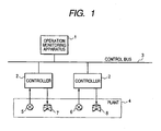
- Fig. 1 shows an exemplary configuration of a general distributed control system.
- an operation monitoring apparatus 1 and a controller 2 are connected to a control bus 3.
- the controller 2 controls a plant 4 under the monitoring of the operation monitoring apparatus 1.
- the operation monitoring apparatus 1 is in charge of operation and monitoring of the plant.
- the operation monitoring apparatus 1 displays a screen to perform control operation and monitoring.
- a plurality of controllers are distributed across the plant.
- the operation monitoring apparatus 1 and the controller 2 communicate with each other to control the plant via the control bus 3.
- Sensor devices 5, 6 present in the plant 4 detects the process values of temperature, pressure and liquid level.
- Valves 7, 8 have their throttle opening controlled by an operation signal given by the controller 2.
- An analog signal of 4 to 20mA and 1 to 5V output from the sensor devices 5, 6 is input to the controller 2.
- a control unit (not shown) in the controller 2 Based on this input, a control unit (not shown) in the controller 2 performs control arithmetic operation and obtains an operation amount.
- the operation amount is output as an analog signal of 4 to 20mA and 1 to 5V, which controls the throttle opening of the valves 7, 8. For example, by controlling the valve throttle opening of a reaction oven the process amount of temperature or pressure is controlled.
- the control bus of a conventional distributed control system is a bus dedicated to process control.
- the protocol for the control bus is a protocol dedicated to process control.
- remarkable progress in IT (Information Technology) or web-related technologies has presented a need for the open architecture of the control bus for a distributed control system.
- As a request for the open architecture a request for a network that is based on Ethernet (registered trademark) is on the rise.
- Industrial Ethernet registered trademark
- the Patent Reference 1 describes a communication control system that employs a redundant configuration of a network adapter transparent to a user application program when a communication station communicating over the TCP/IP (Transmission Control Protocol/Internet Protocol) is connected to Ethernet (registered trademark).
- TCP/IP Transmission Control Protocol/Internet Protocol
- Ethernet registered trademark
- An object of the invention is to provide a communication control system capable of performing communications that satisfy real time property, high reliability and a need for open protocol communications by introducing in the same communication station critical communication section for providing real time property and high reliability as open communication section. This object is achieved by the features as set forth in claim 1. Further advantageous embodiments of the present invention are set forth in the dependent claims.
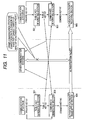
- Fig. 2 is a block diagram showing an embodiment of the invention.
- a communication path 10 is duplicated by a main path 11 and a sub-path 12.
- the communication path 10 is for example the control bus of a distributed control system.
- a communication station 20 and communication stations 31 to 3N are connected to the main path 11 and the sub-path 12.
- the communication station 20 includes a unit 21 for performing communications.
- the embodiment in Fig. 1 includes a single unit.
- high-priority communication section 211 performs high-priority communications.
- Low-priority communication section 212 performs low-priority communications.
- High-priority communications transfer process data, an operation amount, an alarm and the like.
- Low-priority communications performs image data transfer, file transfer, message transfer, and the like. High-priority communications transfer more real time data while low-priority communications are less real time than high-priority communications.
- the high-priority communication section 211 performs communications in accordance with a protocol dedicated to process control.
- the low-priority communication section performs communications in accordance with an open standard protocol.
- the open standard protocol is for example IP (Internet Protocol).
- Communication function implementing section 213a, 213b is duplicated.
- Communication function implementing section 214a, 214b is also duplicated.
- These communication function implementing section are provided to implement the communication function in a predetermined layer of an OSI (Open Systems Interconnection) hierarchical model.
- the communication function implementing section 213a, 213b implements a communication function in the physical layer (first layer) of an OSI hierarchical model.
- the communication function implementing section 214a, 214b implements a communication function in the data link layer (second layer) of an OSI hierarchical model.
- the 213a and 214a are provided to correspond to the main path 11.
- the 213b and 214b are provided to correspond to the sub-path 12.
- the high-priority communication section 211 uses the communication function implementing section 213a and 214a to perform communications on the main path 11.
- the low-priority communication section 212 uses the communication function implementing section 213b and 214b to perform communications on the sub-path 12.
- the high-priority communication section 211 uses the communication function implementing section 213b, 214b and the sub-path 12 to perform communications. In this case, low-priority communications are restricted.
- the high-priority communication section 211 can perform communications by using either the duplicated communication function implementing section 213a, 213b or the communication function implementing section 214a, 214b.
- the low-priority communication section 212 can use only its corresponding communication function implementing section 213b and 214b. In this way, the high-priority communication section 211 and the low-priority communication section 212 coexist in the same communication station.
- the high-priority communication section to provide real time property and high reliability and low-priority communication section that uses an open standard protocol coexist in the same communication station. This provides a communication control system that satisfies a request for industrial applications and a request for open protocol communications at the same time.
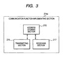
- Fig. 3 shows an exemplary configuration of communication function implementing section for implementing a communication function in the data link layer.
- the configuration will be described taking as an example the communication function implementing section 214a.
- the communication function implementing section 214b has the same configuration.
- an address storing section 215 stores a MAC address corresponding to each of the high-priority communication section 211 and low-priority communication section 212.
- a single MAC (Media Access Control) address is assigned to each of the high-priority communication section 211 and low-priority communication section 212.
- Transmitting section 216 appends a corresponding MAC address to a communication frame depending on whether the transmission requestor is the high-priority communication section 211 or low-priority communication section 212 and transmits the communication frame to a communication path.
- Receiving section 217 compares the destination MAC address of the communication frame received from the communication function implementing section 213a with the MAC address stored by the address storing section 215, and in case a match is found in the comparison result, passes the received communication frame to the pertinent communication section (high-priority communication section 211 or low-priority communication section 212).
- a multicast address storing section to store a plurality of MAC multicast addresses may be provided in place of the address storing section 215.
- the receiving section 217 of the communication function implementing section 214a in case the destination MAC address of the communication frame received from the main path 11 matches any one of the addresses present in the MAC multicast address storing section, passes the communication frame to the high-priority communication section 211 and otherwise passes the communication frame to the low-priority communication section 212. In this way, high-priority communications uses a MAC multicast address for communications.
- FIG. 4 is a block diagram of another embodiment of the invention.
- a communication station 22 includes a dual unit 21a and 21b.
- the unit 21a includes high-priority communication section 211, low-priority communication section 212, communication function implementing section 213a, 213b, 214a, 214b.
- the unit 21b has the same configuration as the unit 21a. In the illustrated example, the unit 21a serves as an active unit and the unit 21b serves as a standby unit.
- the active unit 21a performs communications. When the active unit 21a turns faulty, the unit 21a halts communications and places itself in the standby state. The standby unit 21b switches to the active unit and takes over the communications. In this embodiment, the unit is duplicated thus enhancing the reliability of communications.
- the unit may be triplicated or further being multiplexed.
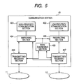
- Fig. 5 is a block diagram of another embodiment.
- a communication station 40 is connected to a main path 11 and a sub-path 12.
- High-priority communication section 401 performs high-priority communications by using the main path 11.
- Low-priority communication section 402 performs low-priority communications by using the sub-path 12.
- Path diagnosing section 403 diagnoses the soundness of the main path 11 and the sub-path 12.
- Switching section 404 switches the communication path between the high-priority communication section 401 and its distant party based on the diagnosis result of the path diagnosing section 403.
- Restricting section 405 restricts communications by the low-priority communication section 402 based on the diagnosis result of the path diagnosing section 403. For example, the restricting section 405 restricts the transmission band of the low-priority communication section 402. Transmitting/Receiving section 406, on receiving a transmission request from the high-priority communication section 401, sequentially transmits communication frames to the main path 11 and passes the communication frames received from the main path 11 to a destination. Transmitting/Receiving section 407, on receiving a transmission request from the low-priority communication section 402, sequentially transmits communication frames to the sub-path 12 and passes the communication frames received from the sub-path 12 to a destination.
- the transmitting/receiving section 406 and 407 respectively correspond to the communication function implementing section 213a, 214a and 213b, 214b in the embodiment shown in Fig. 1 .
- the switching section 404 selects the main path 11 as the communication path of the high-priority communication section 401. In case the path diagnosing section 403 has determined that the main path 11 is faulty, the switching section 404 switches the communication path of the high-priority communication section 401 to the sub-path 12. In case the path diagnosing section 403 has determined that the main path 11 is normal, the restricting section 405 does not restrict the transmission band of the low-priority communication section 402. In case the path diagnosing section 403 has determined that the main path 11 is faulty, the restricting section 405 restricts the transmission band of the low-priority communication section 402. The path diagnosing section 403 also diagnoses the sub-path 12 and, on detecting a fault, generates an alarm.
- the path diagnosing section 403, on determining that the main path 11 is faulty broadcasts the fault in the main path to all communication stations.
- the low-priority communication section 402 determines that the main path is restored to normal operation and halts the transmission control whereby the transmission count is kept below the predetermined value.
- the low-priority communication section 402 may control transmissions so that the transmission count per unit time of low-priority communications will drop below a predetermined value while it is recognizing that the main path 11 is faulty, also in the absence of a broadcast notice that the main path is faulty.
- the low-priority communication section 402 immediately performs high-priority communications when the sub-path 12 is not transmitting and performs low-priority communications when the sub-path 12 is not transmitting and there are no high-priority communications waiting to be transmitted, while it is recognizing that the main path 11 is faulty.
- the high-priority communication section 401 and the low-priority communication section 402 respectively use separate path while the communication path is normal, thus sharing communications in a non-restricted band.
- the communication path of the high-priority communication section 401 is switched to the sub-path and the low-priority communication section 402 is subjected to restriction on the transmission band. This allows high-priority communications continues while maintaining the corresponding band, thus keeping the real time property.
- the communication path of the high-priority communication section 401 is switched to the sub-path although the low-priority communication section 402 is capable of performing communications in a restricted band.
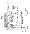
- Fig. 6 is a block diagram of another embodiment.
- Fig. 6 shows a particular configuration example of path diagnosing section.
- the path state storing section 501 stores path state information on whether the communication path from the home station is sound per interface and per distant station.
- Transmitting section 502 receives a transmission request from the high-priority communication section 401, references the path state information in the path state storing section 501, selects a sound communication path and transmits data thereon.
- the transmitting section 502 in case a normal reception response is not received within a predetermined period of time after data transmission, assumes the communication path as faulty and reflects this information on the path state information in the path state storing section 501.
- the receiving section 503 receives data from the distant station and passes the received data to the high-priority communication section 401. When receiving data from the distant communication station, the receiving section 503 returns a normal reception response to the distant communication station. In this way, the transmitting section 502 and the receiving section 503 perform acknowledgment communications whereby diagnosis is made based on whether a normal reception response is received in return for data transmission.
- Fixed cycle path diagnosing section 504 diagnoses the state of the path from the home station cyclically per interface and per distant station, and registers the diagnosis result in the path state storing section 501.
- the fixed cycle path diagnosing section 504 includes diagnosis packet transmitting section (not shown) 505.
- the diagnosis packet transmitting section 505 broadcasts a path diagnosis packet including the information on the receiving state of a path diagnosis packet from another communication station to the other stations.
- the fixed cycle path diagnosing section 504 on receiving a path diagnosis packet, registers in the path state storing section 501 the information on the receiving state of a path diagnosis packet transmitted by the home station included in the received path diagnosis packet as the path state information on the communication path from the home station to the transmission source of the path diagnosis packet.
- An interface 506 makes intervention in the communications between a main path 11 and a communication station 50.
- the interface 507 makes intervention in the communications between a sub-path 12 and the communication station 50.
- a function to perform acknowledgment communications with an actual communication timing and a function to diagnose a path in a fixed cycle irrespective of a communication timing are provided. This allows quick detection of a fault in a path.
- the fixed cycle path diagnosing section 504 may broadcast a path diagnosis packet in accordance with the multicast protocol of the IP (Internet Protocol). In this case, a separate IP multicast address is assigned to each of the main path 11 and the sub-path 12. Each communication station performs broadcasting by using as a destination IP address the IP multicast address corresponding to a path selected between the main path and sub-path and receives a path diagnosis packet where the destination IP address matches the IP multicast address corresponding to the main path or sub-path. With this operation, simultaneous communications to a particular communication station are made possible thus reducing the number of communication circuits.
- IP Internet Protocol
- a sending station may communicate to a communication station on a network where the home station exists as well as a communication station on a network connected via the router. This minimizes the switchover time of communication path thus assuring the real time property of communications.
- Fig. 7 is a block diagram showing another embodiment.
- protocol section 61 performs communication control of a main path 11 and a sub-path 12 duplicated in accordance with a general-purpose connectionless protocol.
- the general-purpose connectionless protocol is for example UDP/IP (User Datagram Protocol/Internet Protocol).
- UDP/IP is a higher level protocol of IP in a protocol group of TCP/IP.
- UDP/IP belongs to the transport layer and is defined in RFC768.
- UDP is a connectionless protocol and does not have such functions as connection management, acknowledgment, sequence, window control and flow control TCP possesses.
- UDP/IP is substantially a protocol whereby an IP packet may be used by an application of the distant station. Including a smaller number of functions, UDP/IP is subject to a lower load thus allowing high-speed data communications. There is no guarantee that data is delivered to the distant party so that it is necessary to provide means for assuring reliability. Reliability is assured by performing acknowledgment communications over UDP/IP.
- switching section 601 switches a data transmitting port between the dual communication path (main path 11 and sub-path 12).
- Data transmitting section 602 transmits the send data of the high-priority communication section 401 to the switching section 601.
- Data receiving section 603 receives data from the main path 11 or sub-path 12 and transmits it to the high-priority communication section 401.
- a timer 604 is activated by a signal TR generated by data transmission by the data transmitting section 602 and reset by a signal RS generated when the data receiving section 603 has received a normal reception response.
- the timer 604 on counting up to a specified value, transmits a time-up signal TU to the data transmitting section 602 to make a retransmission request. Receiving the time-up signal TU, the data transmitting section 602 retransmits the data.
- Counting section 605 counts the number of time-up signals TU and, when a predetermined value is reached, originates a switching signal SW to the switching section 601 to switch over the communication path.
- Path state storing section 606 stores information on the state of the path from the home station to each communication station.
- Registering section 607 determines that the communication path is faulty when the count value of the counting section 605 has reached a specified value and registers in the path state storing section 606 the path state information indicating that the path is faulty.
- connectionless protocol provides an open control bus at the same time.
- a communication path is switched over when the data retransmission count has reached a predetermined value. It is thus possible to prevent switchover of path due to a temporary fault in a communication path. It is also possible to switch over a path while identifying a transient fault and a permanent fault.
- Fig. 8 is a block diagram of another embodiment.
- a multiplexed communication station 70 includes a multiplexed unit 71a, 71b.
- the unit is duplicated.
- the units 71a, 71b each has the same configuration as the communication station 40 shown in Fig. 4 .
- One of the dual units 71a and 71b serves as an active unit and the other serves as a standby unit.
- a separate address is assigned to the low-priority communication section of each unit.
- Each unit is connected to the multiplexed communication path (main path and sub-path).
- the unit 71a is active and the unit 71b is standby.
- Another communication station 72 transmitting to the multiplexed communication station 70 performs communications to the active unit 71a.
- the communication station 72 retries communications to the standby unit 71b.
- Fig. 9 is an explanatory drawing of switching of a control right in the embodiment shown in Fig. 8 .
- Each unit 71a, 71b includes self diagnosing section 73. Assume that the unit 71a is active and the unit 71b is standby. The self diagnosing section 73 in the active unit 71a, on detecting a fault, places itself in the standby state and halts communications. When the unit 71a has halted communications, the standby unit 71b places itself in the active state and starts communications and broadcasts to the other communication stations that it is now an active unit.
- the other communication station 72 includes a table 74 storing information on which unit of the multiplexed communication station 70 is active. The communication station 72 references the information stored in the table 74 to perform transmission to the active unit. On receiving a broadcast from the unit 71b, the communication station 72 updates the information in the table 74.
- a multiplexed communication station assures highly reliable communications.
- Authentication section may be provided in the communication station 40 in Fig. 5 .
- the authentication section performs authentication between high-priority communication section in separate communication stations and enables communications between authenticated communication stations.
- Fig. 10 shows a particular configuration example of authentication section. While the configuration of authentication section is shown in Fig. 10 for convenience of explanation, the communication station 80 also includes the components of the communication station 40.
- Public key generating section 801 generates an electronic public key K2 to be exchanged between the home station and another communication station from an electronic private key K1 unique to the home station.
- Key transmitting section 802 broadcasts the generated public key K2 to all communication stations.
- Common key generating section 803 generates, on a per communication station basis, an electronic common key K3 unique to communication stations 80 and 81 from a public key K2' received from the other station 81 and the private key K1 of the home station and stores the generated common key in the communication station 80.
- the common key generating section 803 uses for example the Differ-Hellman method to generate a common key from a private key and a public key.
- Authentication packet transmitting section 804 uses the generated common key K3 to encrypt a packet or appends an authentication value to a packet.
- the authentication packet transmitting section transmits the encrypted packet or the packet to which the authentication value is attached to another communication station 81.
- Authentication packet receiving section 805 decrypts a packet received from the other communication station 81 by using the common key K3 or determines whether reception is allowed based on the common key and the authentication value attached to the packet.
- Key update section 808 updates a private key for every predetermined time to update a common key.
- Confirming section 806 stores a common key just before update and a latest common key, and confirms an authentication value by using the latest common key on receiving a packet. In case the confirmation is determined illegal, the confirming section 806 confirms the authentication value by using the common key just before update.
- Decoding section 807 decodes a packet by using the common key just before update or the latest common key for which the authentication value is confirmed valid.
- Fig. 11 is an explanatory drawing of the operation of the authentication section shown in Fig. 10 .
- public key generating section 801 generates a public key K2 from the private key K1 of the home station and broadcasts the generated public key K2 to all communication stations.
- the public key generating section 801 generates a public key K2' from the private key K1' of the home station and broadcasts the generated public key to all communication stations.
- common key generating section 803 In the communication station 80, common key generating section 803 generates an electronic common key K3 unique to the communication stations 80 and 81 from the public key K2' received from the communication station 81 and the private key K1 of the home station. Similarly, in the communication station 81, the common key generating section 803 generates an electronic common key K3' unique to the communication stations 80 and 81 from the public key K2 received from the communication station 80 and the private key K1' of the home station. In this way, each communication station generates and stores a common key serving as a common password between itself and another communication station.
- authentication packet transmitting section 804 uses the generated common key K3 to encrypt a packet or adds an authentication value to a packet. The authentication packet transmitting section 804 then transmits the encrypted packet or the packet to which the authentication value is attached to the communication station 81.
- authentication packet receiving section 805 decrypts a packet received from the communication station 80 by using the common key K3' or determines whether reception is allowed based on the common key K3' and the authentication value attached to the packet.
- a communication station to which a public key is not transmitted cannot generate a common key so that it cannot wiretap or tamper a transmitted packet. This assures the security of communications.
- By providing high-priority communications with a common key it is possible to prevent a security attack in open low-priority communications from having an influence on high-priority communications.
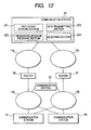
- Fig. 12 is a block diagram showing another embodiment of the invention.
- routers 90, 91 to perform path control of a communication path in accordance with Internet Protocol are provided on a main path and a sub-path respectively.
- the main path is composed of sub-networks 11a, 11b interconnected by the router 90.
- the sub-path is composed of sub-networks 12a, 12b interconnected by the router 91.
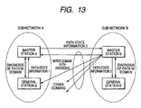
- a sole master station exists on a sub-network.
- the master station transmits an inter-network diagnosing frame.
- the inter-network diagnosing frame includes information on the path between the home station and each of the other communication stations present on a sub-network to which the home station belongs and information on the path between the home station and the master station present on a sub-network to which the home station does not belong.
- the communication station 20 serves as the master station on the sub-network 11a, 12a.
- the communication station 23 serves as the master station on the sub-network 11b, 12b.
- path state storing section 221 stores path state information indicating whether the communication path from the home station to another communication station is sound.
- Diagnosing message receiving section 222 registers in the path state storing section 221 the path state between the home station and a communication station present on a sub-network to which the home station does not belong based on the path state information included in the inter-network diagnosing frame. In the example shown in Fig. 12 , the diagnosing message receiving section 222 registers the path state between the communication station 20 and a communication station on the sub-network 11b, 12b.
- Data transmitting section 223 selects either the main path or sub-path in accordance with the information in the path state storing section 221 and transmits data.
- the path state storing section 221, the diagnosing message receiving section 222 and data transmitting section 223 are provided in a master station and the other communication stations.
- Selecting section 224 prepares a list of the network addresses of all communication stations present on a sub-network and, in case the address of the home station is one uniquely determined from predetermined conditions, causes the home station to operate as the master station on the sub-network.
- the address uniquely determined refers to, for example, the highest address, the lowest address, and the like.
- Fig. 13 is an explanatory drawing of a procedure whereby a communication station obtains path state information.
- communication stations other than the master station are called general stations.
- Sub-networks A and B are interconnected.
- a master station a and a general station a' are interconnected.
- a master station b and a general station b' are interconnected.
- Fig. 14 is a block diagram showing another embodiment, In this embodiment, high-priority communications and low-priority communications share a single communication path.
- a communication station 100 includes protocol interface section 101 for performing high-priority communications and protocol interface section 102 for performing low-priority communications.
- a higher-rank host computer (not shown) communicates with the protocol interface section 101 in accordance with a high-priority communication protocol and communicates with the protocol interface section 102 in accordance with a low-priority communication protocol.
- Communication function implementing section 103 and 104 are provided to correspond to the protocol interface section 101 and 102, respectively. These communication function implementing section 103, 104 implements a communication function in the data link layer (second layer) of an OSI hierarchical model. Priority control section 105 controls transmission from the communication function implementing section 103, 104 based on the priority of the protocol. The communication function implementing section 103, 104 splits a frame into sub-frames below a certain frame length and transmits the resulting sub-frames to the priority control section 105. Communication function implementing section 106 implements a communication function in the physical layer (first layer) of an OSI hierarchical model. High-priority communications and low-priority communications share the communication function implementing section 106. The communication station 100 is connected to the communication path 150. The communication path 150 is shared by low-priority communications and high-priority communications.
- a MAC address register 121 stores a MAC address corresponding to a protocol for high-priority communications.
- Transmission accepting section 122 accepts a frame transmitted by the communication station 100.
- Reception accepting section 123 accepts a frame received by the communication station 100.
- Communication function implementing section 104 has a similar configuration.
- the MAC address register 121 of the communication function implementing section 104 stores a MAC address corresponding to a protocol for low-priority communications.
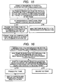
- Fig. 15 is a flowchart showing a transmission procedure.
- transmission accepting section 122 appends the MAC address of a MAC address register 121 to the source address part of the transmission frame received from protocol interface section 101 and temporarily stores the frame.
- the transmission accepting section 122 passes the frame to the priority control section 105, which immediately passes the frame to a communication function implementing section 106.
- the transmission accepting section 122 keeps storing the frame and causes the frame to wait until the transmission allowing signal is driven High.
- the priority control section 105 controls the transmission allowing signal based on the priority assigned to the protocol for high-priority communications. Transmission processing of low-priority communications is the same as above.
- Fig. 16 is a flowchart showing a reception procedure.
- reception accepting section 123 compares the destination address of the reception frame received from the communication function implementing section 106 and the MAC address stored in a MAC address register 121. In case a match is not found, the frame is discarded. In case a match is found, the frame is passed to protocol interface section 101. Reception processing of low-priority communications is the same as above.
- the priority control section 105 classifies communications into high-priority protocol communications and low-priority protocol communications.
- the priority control section 105 always gives a transmission right to the transmission acceptance of a frame of a high-priority protocol unless another frame is being transmitted.
- the priority control section 105 gives a transmission right to the transmission acceptance of a frame of a low-priority protocol unless another frame is being transmitted and no frames are waiting at the transmission acceptance of a high-priority protocol, and immediately causes the frame to be transmitted.
- the priority control section 105 controls transmission of a transmission frame by using the transmission allowing signal so that the transmission count of transmission frames per certain time from the communication function implementing section 103, 104 will drop below a predetermined value assigned to each of the communication function implementing section 103, 104.
- both a network using an open standard protocol and a network using a unique protocol to implement real time communications are necessary in the communications between hosts, interfaces for these protocols are provided in the same communication station and the protocol processing function share the same communication function implementing section and communication path. This reduces the hardware cost and cable laying cost.
- a communication station is present in the operation monitoring apparatus in a distributed control system.
- the unit may be triplicated or further being multiplexed.
- a single main path and a plurality of sub-paths constitute a communication path.
Landscapes
- Engineering & Computer Science (AREA)
- Computer Networks & Wireless Communication (AREA)
- Signal Processing (AREA)
- Computer Security & Cryptography (AREA)
- Small-Scale Networks (AREA)
- Data Exchanges In Wide-Area Networks (AREA)
Claims (8)
- Système de commande de communication pour commander des communications effectuées entre une pluralité de stations de communications (20, 31, ... 3N) qui sont connectées à des voies de communication multiplexées avec une voie principale (11) et avec une sous-voie (12), système de commande de communication comprenant :des premières sections de mise en oeuvre de fonction de communication (213a, 213b) qui sont multiplexées de manière à correspondre respectivement à la voie principale (11) et à la sous-voie (12), et qui mettent chacune en oeuvre une fonction de communication dans une couche physique d'un modèle hiérarchique OSI ;des secondes sections de mise en oeuvre de fonction de communication (214a, 214b) qui sont multiplexées de manière à correspondre respectivement aux premières sections de mise en oeuvre de fonction de communication (213a, 213b) multiplexées, et qui mettent chacune en oeuvre une fonction de communication dans une couche de liaison de données du modèle hiérarchique OSI ;une section de communication de priorité élevée (211) pour effectuer une communication de priorité élevée par l'intermédiaire de la première section de mise en oeuvre de fonction de communication (213a) et de la seconde section de mise en oeuvre de fonction de communication (214a) correspondant chacune à l'une quelconque des voies de communication multiplexées ; etune section de communication de faible priorité (212) pour effectuer une communication de faible priorité par l'intermédiaire de la première section de mise en oeuvre de fonction de communication (213b) et de la seconde section de mise en oeuvre de fonction de communication (214b) correspondant chacune à la sous-voie,dans lequel la section de communication de priorité élevée (211) et la section de communication de faible priorité (212) coexistent dans une station de communication unique (20), et caractérisé en ce quela seconde section de mise en oeuvre de fonction de communication (214a) comprend :une section de stockage d'adresses (215) pour stocker des adresses MAC (contrôle d'accès au support) correspondant respectivement à la section de communication de priorité élevée (211) et à la section de communication de faible priorité (212) ;une section de transmission (216) qui est conçue pour joindre l'adresse MAC correspondante à une trame de communication selon si un demandeur de transmission est la section de communication de priorité élevée (211) ou la section de communication de faible priorité (212), et pour transmettre la trame de communication à la voie de communication ; etune section réceptrice (217) qui est conçue pour comparer une adresse MAC de destination d'une trame de communication reçue de la première section de mise en oeuvre de fonction de communication (213a) à l'adresse MAC stockée dans la section de stockage d'adresses (215), et lorsqu'une correspondance est trouvée dans le résultat de comparaison, envoie la trame de communication reçue à la section de communication correspondante.
- Système de commande de communication conformément à la revendication 1, dans lequel la section de stockage d'adresses (215) est une section de stockage d'adresses de multidiffusion pour stocker une pluralité d'adresses de multidiffusion MAC,
dans lequel, lorsqu'une adresse MAC de destination d'une trame de communication reçue de la voie de communication correspond à l'une quelconque des adresses stockées dans la section de stockage d'adresses de multidiffusion MAC, la seconde section de mise en oeuvre de fonction de communication (214a) envoie la trame de communication à la section de communication de priorité élevée (211), et
autrement, la seconde section de mise en oeuvre de fonction de communication (214a) envoie la trame de communication à la section de communication de faible priorité (212). - Système de commande de communication conformément à la revendication 1 ou 2, dans lequel des unités comprenant chacune la section de communication de priorité élevée (211), la section de communication de faible priorité (212), les premières sections de mise en oeuvre de fonction de communication (213a, 213b), et les secondes sections de mise en oeuvre de fonction de communication (214a, 214b) sont prévues et multiplexées dans une station de communication unique, et
une unité est conçue pour servir d'unité active et l'autre unité est conçue pour servir d'unité de secours. - Système de commande de communication conformément à la revendication 1, dans lequel un routeur (90) pour effectuer une commande de voie de la voie de communication conformément au Protocole Internet est prévu sur la voie de communication, et ladite voie de communication comprend une pluralité de sous-réseaux (11a, 11b) interconnectés par le routeur (90).
- Système de commande de communication conformément à la revendication 4, dans lequel une seule station maîtresse (20) existe sur le sous-réseau (11a, 12a),
la station maîtresse est conçue pour transmettre une trame de diagnostic inter-réseau comprenant des informations d'état de voie sur les voies entre la station de base et toute autre station de communication existant sur le sous-réseau auquel appartient la station de base et des informations d'état de voie sur la voie entre la station de base et une station maîtresse existant sur un sous-réseau auquel la station de base n'appartient pas, et
chacune de l'ensemble des stations de communication sur la pluralité de sous-réseaux comprenant la station maîtresse et les autres stations de communication comprennent :une section de stockage d'état de voie (221) pour stocker des informations d'état de voie indiquant si la voie de communication de la station de base à chacune d'autres stations de communication est ou non opérationnelle;une section réceptrice de message de diagnostic (222) qui est conçue pour enregistrer, dans la section de stockage d'état de voie (221), l'état de voie entre la station de base et la station de communication existant sur le sous-réseau auquel la station de base n'appartient pas, sur la base des informations d'état de voie comprises dans la trame de diagnostic inter-réseau ; etune section de transmission de données (223) qui est conçue pour sélectionner soit la voie principale (11a, 11b), soit la sous-voie (12a, 12b) conformément aux informations contenues dans la section de stockage d'état de voie (221), et pour effectuer une transmission de données. - Système de commande de communication conformément à la revendication 5 comprenant en outre :une section de sélection (224) qui est conçue pour générer une liste d'adresses de réseau de toutes les stations de communication existant sur le sous-réseau, et, dans un cas dans lequel une adresse de la station de base est l'adresse qui est uniquement déterminée dans la liste sur la base d'une condition prédéfinie, pour amener la station de base à fonctionner en tant que station maîtresse sur le sous-réseau.
- Système de commande de communication conformément à la revendication 1, dans lequel la section de communication de priorité élevée (211) est conçue pour effectuer une communication conformément à un protocole dédié à la commande de processus, et
la section de communication de faible priorité (212) est conçue pour effectuer une communication conformément à un protocole de norme ouverte. - Système de commande de communication conformément à la revendication 1, dans lequel la section de communication de priorité élevée (211) est conçue pour transférer des données de traitement et/ou une quantité de fonctionnement et/ou une alarme, et
la section de communication de faible priorité (212) est conçue pour effectuer un transfert de données d'image et/ou un transfert de fichier et/ou un transfert de message.
Applications Claiming Priority (2)
| Application Number | Priority Date | Filing Date | Title |
|---|---|---|---|
| JP2003415989A JP3651612B1 (ja) | 2003-12-15 | 2003-12-15 | 通信制御システム |
| PCT/JP2004/011537 WO2005060168A1 (fr) | 2003-12-15 | 2004-08-11 | Systeme de commande de communication |
Publications (3)
| Publication Number | Publication Date |
|---|---|
| EP1696604A1 EP1696604A1 (fr) | 2006-08-30 |
| EP1696604A4 EP1696604A4 (fr) | 2011-08-24 |
| EP1696604B1 true EP1696604B1 (fr) | 2013-02-27 |
Family
ID=34650608
Family Applications (1)
| Application Number | Title | Priority Date | Filing Date |
|---|---|---|---|
| EP04771522A Expired - Lifetime EP1696604B1 (fr) | 2003-12-15 | 2004-08-11 | Systeme de commande de communication |
Country Status (5)
| Country | Link |
|---|---|
| US (1) | US8130636B2 (fr) |
| EP (1) | EP1696604B1 (fr) |
| JP (1) | JP3651612B1 (fr) |
| CN (1) | CN1894901B (fr) |
| WO (1) | WO2005060168A1 (fr) |
Families Citing this family (9)
| Publication number | Priority date | Publication date | Assignee | Title |
|---|---|---|---|---|
| JP4728209B2 (ja) * | 2006-12-05 | 2011-07-20 | アラクサラネットワークス株式会社 | マルチキャストネットワーク冗長化システム |
| US8577220B1 (en) * | 2008-02-28 | 2013-11-05 | Aurora Networks, Inc. | Method and system for protecting against communication loss in an optical network system |
| JP5636995B2 (ja) * | 2011-02-07 | 2014-12-10 | セイコーエプソン株式会社 | ネットワーク通信装置、方法、及びプログラム |
| US9525739B2 (en) * | 2013-05-09 | 2016-12-20 | Mitsubishi Electric Corporation | FA network LSI and communication device |
| US10182015B2 (en) | 2014-07-29 | 2019-01-15 | Siemens Aktiengesellschaft | Redundant transmission of data frames in communication networks having a ring topology |
| JP2018092352A (ja) | 2016-12-02 | 2018-06-14 | セイコーエプソン株式会社 | 情報収集サーバー、デバイスおよび情報収集送信システム |
| JP6816554B2 (ja) * | 2017-02-22 | 2021-01-20 | オムロン株式会社 | 制御システム、制御装置および制御プログラム |
| CN110086211B (zh) * | 2019-05-06 | 2021-04-30 | 国家电网公司东北分部 | 适用于大规模交直流混联电网的高频集中控制方法 |
| CN114726673B (zh) * | 2022-03-22 | 2023-10-31 | 深圳渊联技术有限公司 | Modbus TCP协议通信方法及通信系统 |
Family Cites Families (8)
| Publication number | Priority date | Publication date | Assignee | Title |
|---|---|---|---|---|
| JP2951816B2 (ja) * | 1993-04-23 | 1999-09-20 | 三菱電機株式会社 | 通信制御方法 |
| JPH10322377A (ja) * | 1997-05-16 | 1998-12-04 | Nec Corp | リング形パス選択方式 |
| US5959968A (en) * | 1997-07-30 | 1999-09-28 | Cisco Systems, Inc. | Port aggregation protocol |
| JP3511875B2 (ja) | 1998-01-13 | 2004-03-29 | 横河電機株式会社 | 通信制御システム |
| JP2000004275A (ja) * | 1998-06-17 | 2000-01-07 | Oki Electric Ind Co Ltd | 送受信システム |
| JP3729101B2 (ja) * | 2001-08-22 | 2005-12-21 | 日本電気株式会社 | 二重リング型データ伝送方法及び伝送システム |
| GB2379356B (en) * | 2001-08-31 | 2003-10-22 | Roke Manor Research | A method of controlling data routing on a network |
| WO2003062955A2 (fr) * | 2002-01-22 | 2003-07-31 | Sharp Laboratories Of America, Inc. | Systemes et procedes d'accuse de reception de trafic de multi-diffusion |
-
2003
- 2003-12-15 JP JP2003415989A patent/JP3651612B1/ja not_active Expired - Lifetime
-
2004
- 2004-08-11 CN CN2004800374593A patent/CN1894901B/zh not_active Expired - Lifetime
- 2004-08-11 EP EP04771522A patent/EP1696604B1/fr not_active Expired - Lifetime
- 2004-08-11 US US10/583,079 patent/US8130636B2/en active Active
- 2004-08-11 WO PCT/JP2004/011537 patent/WO2005060168A1/fr not_active Ceased
Also Published As
| Publication number | Publication date |
|---|---|
| JP2005176161A (ja) | 2005-06-30 |
| US8130636B2 (en) | 2012-03-06 |
| US20070250182A1 (en) | 2007-10-25 |
| CN1894901A (zh) | 2007-01-10 |
| JP3651612B1 (ja) | 2005-05-25 |
| EP1696604A4 (fr) | 2011-08-24 |
| WO2005060168A1 (fr) | 2005-06-30 |
| CN1894901B (zh) | 2011-06-01 |
| EP1696604A1 (fr) | 2006-08-30 |
Similar Documents
| Publication | Publication Date | Title |
|---|---|---|
| CN102904818B (zh) | 一种arp信息表项更新方法及装置 | |
| CN101146014B (zh) | 容错以太网 | |
| CN102025610B (zh) | 自动化设备的通信网络中涉及安全的通信的方法和装置 | |
| US7697538B2 (en) | Data transfer method and automation system used in said data transfer method | |
| CN104954105B (zh) | 接收器网络部件、通信网络和用于运行通信网络的方法 | |
| KR20150100790A (ko) | 프로토콜 예외 상태를 이용하는 데이터 전송 | |
| US7269661B2 (en) | Method using receive and transmit protocol aware logic modules for confirming checksum values stored in network packet | |
| CN107852415B (zh) | 用于在网络之间无反作用地传输数据的方法和装置 | |
| US20100091784A1 (en) | Filtering of redundant frames in a network node | |
| EP1696604B1 (fr) | Systeme de commande de communication | |
| WO2021005875A1 (fr) | Système de communication embarqué, dispositif embarqué et procédé de communication de véhicule | |
| JPH09130408A (ja) | ネットワークインタフェース装置 | |
| CN102082696A (zh) | 一种冗余网络系统以及基于该系统的报文发送方法 | |
| CN101465762B (zh) | 一种检测保护组端口间错连的方法、设备及系统 | |
| CN111656737A (zh) | 用于工业自动化系统的无线电通信系统和用于运行无线电通信系统的方法 | |
| JP3994440B2 (ja) | 通信制御システム | |
| CN118118290A (zh) | 一种基于trdp的网络通信架构和多路冗余数据处理方法 | |
| CN113875195B (zh) | 网络分配器、自动化网络和用于在自动化网络中传输数据的方法 | |
| CN1969236A (zh) | 数据传输方法及使用此种数据传输方法的自动化系统 | |
| CN106161057B (zh) | 一种用户侧的网关保护方法、网关设备及系统 | |
| KR102951113B1 (ko) | 원자력 발전소 및 기타 산업 시설의 자동 모니터링 및 제어 시스템을 위한 이중 버스 | |
| JP3380957B2 (ja) | 二重化通信制御装置 | |
| CN100496005C (zh) | 一种大规模网络控制系统 | |
| CN100518041C (zh) | 监测数据传输的方法和装置 | |
| JP7841284B2 (ja) | 通信装置及び通信方法 |
Legal Events
| Date | Code | Title | Description |
|---|---|---|---|
| PUAI | Public reference made under article 153(3) epc to a published international application that has entered the european phase |
Free format text: ORIGINAL CODE: 0009012 |
|
| 17P | Request for examination filed |
Effective date: 20060613 |
|
| AK | Designated contracting states |
Kind code of ref document: A1 Designated state(s): DE NL |
|
| RIN1 | Information on inventor provided before grant (corrected) |
Inventor name: SOGO, SADOTOSHI,YOKOGAWA ELECTRIC CORPORATION Inventor name: HONGO, TAKESHI,YOKOGAWA ELECTRIC CORPORATION Inventor name: YOKOI, TOYOAKI,YOKOGAWA ELECTRIC CORPORATION Inventor name: MURAKAMI, MASUYUKITHE UNIVERSITY OF ELECTRO-COMM. Inventor name: HABAGUCHI, KENJI,YOKOGAWA ELECTRIC CORPORATION Inventor name: NAKAJIMA, TAKESHI,YOKOGAWA ELECTRIC CORPORATION Inventor name: AKABANE, KUNIHARU,YOKOGAWA ELECTRIC CORPORATION Inventor name: EBASHI, HIROMICHI,YOKOGAWA ELECTRIC CORPORATION Inventor name: DEMACHI, KOJI,YOKOGAWA ELECTRIC CORPORATION Inventor name: ISHII, AKINORI,YOKOGAWA ELECTRIC CORPORATION |
|
| DAX | Request for extension of the european patent (deleted) | ||
| RBV | Designated contracting states (corrected) |
Designated state(s): DE NL |
|
| A4 | Supplementary search report drawn up and despatched |
Effective date: 20110725 |
|
| RIC1 | Information provided on ipc code assigned before grant |
Ipc: H04L 12/56 20060101ALI20110719BHEP Ipc: H04L 12/28 20060101AFI20110719BHEP |
|
| 17Q | First examination report despatched |
Effective date: 20120419 |
|
| GRAP | Despatch of communication of intention to grant a patent |
Free format text: ORIGINAL CODE: EPIDOSNIGR1 |
|
| GRAS | Grant fee paid |
Free format text: ORIGINAL CODE: EPIDOSNIGR3 |
|
| GRAA | (expected) grant |
Free format text: ORIGINAL CODE: 0009210 |
|
| AK | Designated contracting states |
Kind code of ref document: B1 Designated state(s): DE NL |
|
| RIC1 | Information provided on ipc code assigned before grant |
Ipc: H04L 12/801 20130101ALI20130122BHEP Ipc: H04L 12/28 20060101AFI20130122BHEP |
|
| REG | Reference to a national code |
Ref country code: DE Ref legal event code: R096 Ref document number: 602004041159 Country of ref document: DE Effective date: 20130425 |
|
| REG | Reference to a national code |
Ref country code: NL Ref legal event code: T3 |
|
| PLBE | No opposition filed within time limit |
Free format text: ORIGINAL CODE: 0009261 |
|
| STAA | Information on the status of an ep patent application or granted ep patent |
Free format text: STATUS: NO OPPOSITION FILED WITHIN TIME LIMIT |
|
| 26N | No opposition filed |
Effective date: 20131128 |
|
| REG | Reference to a national code |
Ref country code: DE Ref legal event code: R097 Ref document number: 602004041159 Country of ref document: DE Effective date: 20131128 |
|
| PGFP | Annual fee paid to national office [announced via postgrant information from national office to epo] |
Ref country code: NL Payment date: 20140710 Year of fee payment: 11 |
|
| REG | Reference to a national code |
Ref country code: NL Ref legal event code: MM Effective date: 20150901 |
|
| PG25 | Lapsed in a contracting state [announced via postgrant information from national office to epo] |
Ref country code: NL Free format text: LAPSE BECAUSE OF NON-PAYMENT OF DUE FEES Effective date: 20150901 |
|
| P01 | Opt-out of the competence of the unified patent court (upc) registered |
Effective date: 20230603 |
|
| PGFP | Annual fee paid to national office [announced via postgrant information from national office to epo] |
Ref country code: DE Payment date: 20230627 Year of fee payment: 20 |
|
| REG | Reference to a national code |
Ref country code: DE Ref legal event code: R071 Ref document number: 602004041159 Country of ref document: DE |