EP1698121B1 - Amélioration de synchronisation et d'estimation du canal dans des systèmes de communication de type WLAN en utilisant un préambule à structure modifiée - Google Patents
Amélioration de synchronisation et d'estimation du canal dans des systèmes de communication de type WLAN en utilisant un préambule à structure modifiée Download PDFInfo
- Publication number
- EP1698121B1 EP1698121B1 EP04808600.3A EP04808600A EP1698121B1 EP 1698121 B1 EP1698121 B1 EP 1698121B1 EP 04808600 A EP04808600 A EP 04808600A EP 1698121 B1 EP1698121 B1 EP 1698121B1
- Authority
- EP
- European Patent Office
- Prior art keywords
- symbol
- preamble
- correlation
- auto
- symbols
- Prior art date
- Legal status (The legal status is an assumption and is not a legal conclusion. Google has not performed a legal analysis and makes no representation as to the accuracy of the status listed.)
- Expired - Lifetime
Links
- 238000004891 communication Methods 0.000 title description 4
- 238000000034 method Methods 0.000 claims description 90
- 239000013256 coordination polymer Substances 0.000 claims description 13
- 230000003111 delayed effect Effects 0.000 claims description 10
- 238000012790 confirmation Methods 0.000 claims description 8
- 239000000969 carrier Substances 0.000 claims description 4
- 125000004122 cyclic group Chemical group 0.000 claims description 4
- 239000011159 matrix material Substances 0.000 claims description 4
- 238000012545 processing Methods 0.000 claims description 2
- 238000001514 detection method Methods 0.000 description 35
- 238000004422 calculation algorithm Methods 0.000 description 9
- 230000005540 biological transmission Effects 0.000 description 7
- 238000004364 calculation method Methods 0.000 description 7
- 238000012549 training Methods 0.000 description 7
- 230000000875 corresponding effect Effects 0.000 description 4
- 230000015556 catabolic process Effects 0.000 description 3
- 238000006731 degradation reaction Methods 0.000 description 3
- 238000004088 simulation Methods 0.000 description 3
- 230000002596 correlated effect Effects 0.000 description 2
- 238000005516 engineering process Methods 0.000 description 2
- 230000001360 synchronised effect Effects 0.000 description 2
- 239000000654 additive Substances 0.000 description 1
- 230000000996 additive effect Effects 0.000 description 1
- 230000001419 dependent effect Effects 0.000 description 1
- 230000002708 enhancing effect Effects 0.000 description 1
- 238000004519 manufacturing process Methods 0.000 description 1
- 230000000737 periodic effect Effects 0.000 description 1
- 229940034880 tencon Drugs 0.000 description 1
Images


Classifications
-
- H—ELECTRICITY
- H04—ELECTRIC COMMUNICATION TECHNIQUE
- H04L—TRANSMISSION OF DIGITAL INFORMATION, e.g. TELEGRAPHIC COMMUNICATION
- H04L27/00—Modulated-carrier systems
- H04L27/26—Systems using multi-frequency codes
-
- H—ELECTRICITY
- H04—ELECTRIC COMMUNICATION TECHNIQUE
- H04L—TRANSMISSION OF DIGITAL INFORMATION, e.g. TELEGRAPHIC COMMUNICATION
- H04L27/00—Modulated-carrier systems
- H04L27/26—Systems using multi-frequency codes
- H04L27/2601—Multicarrier modulation systems
- H04L27/2647—Arrangements specific to the receiver only
- H04L27/2655—Synchronisation arrangements
- H04L27/2656—Frame synchronisation, e.g. packet synchronisation, time division duplex [TDD] switching point detection or subframe synchronisation
-
- H—ELECTRICITY
- H04—ELECTRIC COMMUNICATION TECHNIQUE
- H04L—TRANSMISSION OF DIGITAL INFORMATION, e.g. TELEGRAPHIC COMMUNICATION
- H04L25/00—Baseband systems
- H04L25/02—Details ; arrangements for supplying electrical power along data transmission lines
- H04L25/0202—Channel estimation
-
- H—ELECTRICITY
- H04—ELECTRIC COMMUNICATION TECHNIQUE
- H04L—TRANSMISSION OF DIGITAL INFORMATION, e.g. TELEGRAPHIC COMMUNICATION
- H04L27/00—Modulated-carrier systems
- H04L27/26—Systems using multi-frequency codes
- H04L27/2601—Multicarrier modulation systems
- H04L27/2602—Signal structure
- H04L27/261—Details of reference signals
- H04L27/2613—Structure of the reference signals
-
- H—ELECTRICITY
- H04—ELECTRIC COMMUNICATION TECHNIQUE
- H04L—TRANSMISSION OF DIGITAL INFORMATION, e.g. TELEGRAPHIC COMMUNICATION
- H04L27/00—Modulated-carrier systems
- H04L27/26—Systems using multi-frequency codes
- H04L27/2601—Multicarrier modulation systems
- H04L27/2647—Arrangements specific to the receiver only
- H04L27/2655—Synchronisation arrangements
- H04L27/2662—Symbol synchronisation
- H04L27/2663—Coarse synchronisation, e.g. by correlation
-
- H—ELECTRICITY
- H04—ELECTRIC COMMUNICATION TECHNIQUE
- H04L—TRANSMISSION OF DIGITAL INFORMATION, e.g. TELEGRAPHIC COMMUNICATION
- H04L7/00—Arrangements for synchronising receiver with transmitter
- H04L7/04—Speed or phase control by synchronisation signals
- H04L7/10—Arrangements for initial synchronisation
-
- H—ELECTRICITY
- H04—ELECTRIC COMMUNICATION TECHNIQUE
- H04W—WIRELESS COMMUNICATION NETWORKS
- H04W56/00—Synchronisation arrangements
- H04W56/001—Synchronization between nodes
-
- H—ELECTRICITY
- H04—ELECTRIC COMMUNICATION TECHNIQUE
- H04L—TRANSMISSION OF DIGITAL INFORMATION, e.g. TELEGRAPHIC COMMUNICATION
- H04L25/00—Baseband systems
- H04L25/02—Details ; arrangements for supplying electrical power along data transmission lines
- H04L25/0202—Channel estimation
- H04L25/0224—Channel estimation using sounding signals
- H04L25/0226—Channel estimation using sounding signals sounding signals per se
-
- H—ELECTRICITY
- H04—ELECTRIC COMMUNICATION TECHNIQUE
- H04L—TRANSMISSION OF DIGITAL INFORMATION, e.g. TELEGRAPHIC COMMUNICATION
- H04L27/00—Modulated-carrier systems
- H04L27/26—Systems using multi-frequency codes
- H04L27/2601—Multicarrier modulation systems
- H04L27/2602—Signal structure
- H04L27/2605—Symbol extensions, e.g. Zero Tail, Unique Word [UW]
- H04L27/2607—Cyclic extensions
-
- H—ELECTRICITY
- H04—ELECTRIC COMMUNICATION TECHNIQUE
- H04L—TRANSMISSION OF DIGITAL INFORMATION, e.g. TELEGRAPHIC COMMUNICATION
- H04L27/00—Modulated-carrier systems
- H04L27/26—Systems using multi-frequency codes
- H04L27/2601—Multicarrier modulation systems
- H04L27/2602—Signal structure
- H04L27/261—Details of reference signals
- H04L27/2613—Structure of the reference signals
- H04L27/26132—Structure of the reference signals using repetition
-
- H—ELECTRICITY
- H04—ELECTRIC COMMUNICATION TECHNIQUE
- H04W—WIRELESS COMMUNICATION NETWORKS
- H04W84/00—Network topologies
- H04W84/02—Hierarchically pre-organised networks, e.g. paging networks, cellular networks, WLAN [Wireless Local Area Network] or WLL [Wireless Local Loop]
- H04W84/10—Small scale networks; Flat hierarchical networks
- H04W84/12—WLAN [Wireless Local Area Networks]
Definitions
- the present invention relates to a preamble configuring method and a frame synchronization detection method in a wireless local area network system, and more particularly it relates to a preamble configuring method and a detection method for data frame synchronization in a 60GHz wireless local area network system.
- a preamble signal is transmitted to a receiver at the beginning of the data frame and the receiver detects the start of frame transmission and performs a symbol timing detection for demodulation using the preamble signal.
- WLAN wireless local area network
- Methods for detecting the symbol timing, an auto-correlation or a cross-correlation of a received signal may be employed.
- the cross-correlation requires lots of calculations in every clock period and may cause serious performance degradation due to a carrier frequency offset, whereas the auto-corretation requires less calculations and can be simply implemented.
- Synchronization Technique for HIPERLAN/2 (IEEE 54th Vehicular Technology Conference, vol. 2, p.762 ⁇ 766, 2001, by V. Almenar ) is related to a method for detecting frame synchronization by using the phase and amplitude of auto-correlation in a 5GHz OFDM (Orthogonal Frequency Division Multiplexing) WLAN system.
- 5GHz OFDM Orthogonal Frequency Division Multiplexing
- the above-disclosed transaction may not be available for estimating carrier frequency offset in a 60GHz WLAN system.
- EP 1313283 A2 describes a method for synchronizing the timing in a receiver to an orthogonal frequency division multiplex (OFDM) signal transmitted over a channel.
- the OFDM signal includes multiple training symbols, including long and short training symbols.
- the first half of the training symbols is correlated with the second half to determine a coarse index which is used to adjust the unsynchronized OFDM.
- the first training symbol is then correlated with the last training symbol to determine a fine index to adjust the coarsely adjusted OFDM signal so that the receiver is synchronized with the transmitted OFDM signal.
- EP 1317094A2 presents a method and apparatus that allows rapid detection of the boundary and only a small amount of the new sequence needs to be received prior to the detection of the boundary. Additionally, the method and apparatus can be used to detect the presence of a transmission on the communications medium.
- the method does frame detection using a threshold comparison mechanism and performs orthogonal frequency division multiplexing (OFDM) symbol boundary detection using correlation techniques of self and cross-correlation information to achieve symbol timing synchronization.
- OFDM orthogonal frequency division multiplexing
- WLAN wireless local area network
- a method for configuring a preamble of a downlink frame for synchronization and channel estimation in a wireless local area network system comprises the steps provided in claim 1.
- WLAN wireless local area network
- a transmitter transmits a preamble or a training signal to a receiver to pre-notify data frame transmission before the actual data frame is transmitted.
- the receiver therefore perceives that the actual data frame will be transmitted by receiving the preamble or the training signal.
- a downlink physical layer preamble and an uplink physical layer preamble are implemented, and methods for detecting start of data frame transmission by employing auto-correlation of periodic and continuous preamble signals and detecting frame synchronization by using the phase and amplitude of the auto-correlation are provided.
- the frame synchronization detection includes timing estimation to enhance timing accuracy.
- the frame synchronization algorithm is employed because the 60GHz WLAN system supports the orthogonal frequency division multiplexing (OFDM)/time division duplex (TDD) system.
- OFDM orthogonal frequency division multiplexing
- TDD time division duplex
- a pre-compensation method is used without considering a short preamble of the upper link.
- Protocol data unit trains input to an upper layer are added with preambles for synchronization and channel estimation and mapped into the physical layer (PHY) bursts.
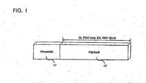
- FIG. 1 illustrates a DL PDU train for the 60GHz WLAN system .
- the DL PDU train includes a preamble 11 and a payload 12.
- the DL PDU train is mapped to the DL PHY burst which is generated by adding the preamble 11 to a plurality of baseband OFDM symbols.
- FIG. 2 illustrates a structure of a DL preamble for the 60GHz WLAN system .
- the DL preamble has the length of T P , and includes a short preamble 21 having the length of T sp and a long preamble 22 having the length of T LP .
- the short preamble 21 is used by the receiver for time and frequency synchronization.
- FIG. 3 illustrates a structure of the short preamble in a time domain of the 60GHz WLAN system according to an exemplary embodiment of the present invention.
- the short preamble has S symbols 31 and 32 that are repeated 16 times within a data symbol period, and an IS symbol 33 having the length of a guard interval (hereinafter, referred to as cyclic prefix CP).
- cyclic prefix CP There is a 180° phase difference between the S symbol and the IS symbol.
- a frequency domain signal of the short preamble is given as Equation 1.
- a time domain signal of the short preamble is formed by adding the IS symbol to a signal that is an Inverse Fast Fourier-Transform (IFFT) processed frequency domain signal.
- IFFT Inverse Fast Fourier-Transform
- C s , m 4 is calculated by inverting 0 into -1 in a matrix generated by an m-sequence generator of a fourth-degree polynomial x 4 + x +1, and s is an initial value.
- FIG. 4 illustrates a structure of a long preamble in the time domain of the 60GHz WLAN system.
- the long preamble having the length of T LP is used by the receiver for fine frequency offset estimation and channel estimation.
- the long preamble includes two L symbols 42 and 43 respectively having the length of T LP and a long CP 41.
- the length of the L symbol is twice as long as that of the data symbol period, and the length of the long CP 41 is twice as long as that of the CP of the IS symbol 33.
- a frequency domain signal of the long preamble is given as Equation 2.
- a time domain signal of the long preamble is formed by inserting a signal and the long CP 41 that is twice as long as the CP of the IS symbol 33, the signal being generated by the IFFT-processing the frequency domain signal and repeating the IFFT processed frequency domain signal twice.
- C s , m 8 is calculated by inverting 0 into -1 in a matrix generated from an m-sequence generator of an eight-degree polynomial x 8 + x 7 + x 6 + x +1, and s denotes an initial value.
- FIG. 5 illustrates parameters of the preamble in the time domain of the 60GHz WLAN system.
- Each wireless terminal (WT) estimates a carrier frequency by using a DL preamble of a DL sub-frame and maintains the UL carrier frequency offset within 1% of a difference between the sub-carrier frequencies since the uplink (UL) burst has no periodical UL preamble. Further, adequate transmission power for the UL is derived from average transmission power of an access point (AP) estimated by the DL preamble. In other words, the UL signal transmitted to the AP does not require carrier frequency restoration and automatic gain control (AGC) processes, and the estimated carrier frequency offset is small, such that the CP is used to estimate symbol timing.
- AGC automatic gain control
- the frame synchronization is used to find the start point of each frame and estimate the frame timing for fine symbol timing estimation.
- Frame synchronization performance is defined by referring to the following criteria: timing accuracy, false alarm (FA), and detention failure probability (DF).
- timing accuracy and the false alarm are regarded as one criterion.
- the frame synchronization is affected by the length of an auto-correlation window. However, a detection range is controlled to correspond to the length of the window when referring to the criteria for the frame synchronization.
- FIG. 6 depicts a process of the frame synchronization estimation when the CP is inserted to the short preamble instead of inserting the IS symbol thereto in the 60GHz WLAN system.
- a performance range of the cross-correlation is set to be within 16 samples. Accordingly, the detection range of the frame synchronization is set within ⁇ 8 samples from a start point of the corresponding preamble.
- the length of the auto-correlation window is set to be greater than 16 samples, start of the frame may be found within the preamble but the detection range may not satisfactory, thereby causing an increase of an FA. In other words, timing accuracy may cause performance degradation.
- FIG. 7 to FIG. 10 respectively show length-specified auto-correlation when performing the frame synchronization in the 60GHz WLAN system according to the present invention.
- the frame may not be synchronized because a peak difference between the first peak and the second peak is less than -6 dB when the length of the window is less than 16 samples and a signal-to-noise ratio is set to be zero.
- a first method is proposed to solve the foregoing problem by using an auto-correlation window of sufficient length to extend the detection range.
- a received signal is delayed by an auto-correlation delay N Delay , the received signal is multiplied by a conjugate complex of the delayed signal, a result of the multiplication is stored in a shift register having a window length of N WS , and an average value of results stored in the shift register is calculated to thus detect a threshold value, find a maximum position, and detect the symbol timing.
- FIG. 11 illustrates a process of symbol timing detection using the auto-correlation according to the present invention
- FIG. 11 and Equation 3 summarize a process of the method.
- a multiplication result 83 of a received signal y n and a signal y n - N Delay 82 becomes an input of a moving average block 84.
- the signal y n - N Delay is a signal that is delayed by an N Delay sample 81 and converted into a conjugate complex 82.
- a square value.86 of the received signal that is delayed by the N Delay sample 85 is also input to a moving average block 87 to calculate an average value 89 to thereby obtain a final value ⁇ n .
- the final value ⁇ n corresponding to a correlation coefficient is obtained by Equation 3.
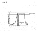
- FIG. 12 illustrates a symbol timing detection including an additional auto-correlation designed to reduce the probability of an FA according to the present invention.
- a confirmation process is repeated once to reduce the probability of an FA.
- a final value ⁇ n - confirm corresponding to the correlation coefficient for confirmation is obtained by Equation 4.
- Delay ⁇ N confirm ⁇ i 2
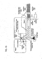
- FIG. 13 illustrates a process of symbol timing detection including the auto-correlation for the confirmation process according to the present invention.
- the process of the symbol timing detection of FIG. 13 is similar to that of FIG. 11 , except blocks 101 and 106 for confirmation of the auto-correlation, and a detailed description thereof will thus be omitted.
- the first method proposes to use a window of sufficient length to reduce the probability of DF and FA, which however increases complexity of realization on the first method. Therefore, a process of timing detection is added to the frame synchronization process to increase timing accuracy in a second method of the present invention.
- an auto-correlator having a window length of N samples is used to find the start point of the frame, find the highest peak of the auto-correlation within the N samples and accordingly increase the timing accuracy within ⁇ 8 samples.
- FIG. 14 is a preamble structure designed for the first method. It illustrates a process of frame synchronization when inserting the IS symbol instead of inserting the CP symbol in the short preamble of the 60GHz WLAN system according to the present invention.
- the IS symbol is inserted at the last period having the CP length in the time domain and the fine symbol timing estimation employing the cross-correlation is performed thereon by using S 16 and the IS symbol, the corresponding performance overcomes the restriction of the detection range, and the detection range and the length of the auto-correlation window can be set without restriction.
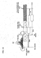
- FIG. 15 illustrates that the symbol timing estimation process is added to the frame synchronization process in order to improve timing accuracy, the frame synchronization having periodically repeated signals for radio data communication.
- the auto-correlation must produce a sharp peak by way of inserting the IS symbol in an appropriate location in the short preamble.
- the 6 th S symbol in the current short preamble of FIG. 15 must be replaced with the IS symbol in consideration of the window length of 64 samples and an interval between each of the windows of 16 samples.
- the above-described method may cause performance degradation since the probability of DF is increased because of reduction of the peak in the preamble period compared to the peak of the first method, and the probability of FA is also increased due to an offset of the timing accuracy.
- the method advantageously reduces the calculation amount in the fine symbol timing estimation.
- the first method is simulated in the Additive White Gaussian Noise (AWGN), LOS (Line of Sight), and NLOS (Non-Line of Sight) channel models, and a signal-to-noise ratio (SNR) is set to be 5dB and 10dB, the size of a frame is set to be 200 symbols, and no clipping has been made.
- AWGN Additive White Gaussian Noise
- LOS Line of Sight
- NLOS Non-Line of Sight
- FIG. 16 illustrates a simulation result for determining the window length in consideration of a calculation amount in the frame synchronization and the fine symbol timing estimation according to the exemplary embodiment of the present invention.
- the detection range is given to be ⁇
- FIG. 17 to FIG. 19 illustrate a result of channel-specified frame synchronization performance when the window length is set to be 64 samples and the detection range is set to be 64 ( ⁇ 32) samples according to the present invention.
- 'FAR' denotes a confirmation process is included to the channel-specified frame synchronization performance to reduce the probability of FA, and the second method is analyzed as a frame synchronization algorithm for enhancing timing accuracy.
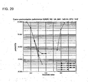
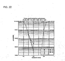
- FIG. 20 to FIG. 22 illustrate a result of the frame synchronization algorithm when the auto-correlation window length is set to be 64 samples, the detection ranges are respectively set to be 16, 32, and 62 samples in the second method.
- FIG. 23 shows a table comparing the frame synchronization using the algorithm according to the first method and the frame synchronization within 16 samples as the detection range according to the second method when the SNR is set to be 5dB in both cases.
- a result of the comparison shows that the probability of DF is the same in both cases, and the probability of FA is greater in the second method.
- a calculation amount in the fine symbol detection of the second method is four times less than that of the first method.
- FIG. 24 shows a table comparing the frame synchronization using the algorithm according to the first method and the frame synchronization within 64 samples as the detection range according to the second method when the SNR is set to be 5dB in both cases.
- the probability of FA is lower in the second method, but it is preferred to consider a method for expanding the detection range of the first method.
- the start point of each frame is detected when a data frame/packet is transmitted/received in the 60GHz WLAN system to thereby obtain high credibility when a receiver demodulates a signal, and increase capacity of the 60GHz WLAN system.
- implementation of the 60GHz WLAN system is less complicated and the cost for manufacturing an integral circuit IC is reduced. Further, when the present invention is applied to a wireless terminal which is sensitive to power consumption, the wireless terminal can be used without recharging it for a comparatively longer time.
Landscapes
- Engineering & Computer Science (AREA)
- Computer Networks & Wireless Communication (AREA)
- Signal Processing (AREA)
- Power Engineering (AREA)
- Synchronisation In Digital Transmission Systems (AREA)
- Mobile Radio Communication Systems (AREA)
- Physics & Mathematics (AREA)
- Discrete Mathematics (AREA)
- General Physics & Mathematics (AREA)
- Mathematical Physics (AREA)
- Data Exchanges In Wide-Area Networks (AREA)
Claims (17)
- Procédé pour configurer un préambule d'une trame de liaison descendante pour une synchronisation et une estimation de canal dans un système de réseau local sans fil, le procédé comprenant :a) agencer un court préambule (21), utilisé pour la synchronisation dans un récepteur, à un point de départ d'une salve, dans lequel l'agencement du court préambule comprendagencer de manière répétée une pluralité de symboles, appelés symboles S, au point de départ de la salve, dans lequel un symbole S est répété 16 fois pour former les symboles S, etagencer un symbole, appelé symbole IS, après les symboles S, dans lequel le symbole IS a la même longueur que le symbole S, et dans lequel il y a une différence de phase de 180° entre le symbole S et le symbole IS, le court préambule comprenant les symboles S et le symbole IS ; etb) agencer un long préambule (22) utilisé pour l'estimation de canal dans le récepteur après le court préambule, dans lequel l'agencement du long préambule comprendagencer de manière répétée une pluralité de symboles, appelés symboles L (42, 43), dans lequel un symbole L est répété deux fois pour former les symboles L (42, 43), etagencer un symbole, appelé long CP (41), dont la longueur est plus courte que la longueur du symbole L, le long préambule (22) comprenant les symboles L (42, 43) et le long CP.
- Procédé selon la revendication 1, dans lequel un signal de domaine fréquentiel SPk du court préambule est défini par l'équation suivante :


- Procédé selon la revendication 2, dans lequel un signal de domaine temporel du court préambule est formé en ajoutant le symbole IS (33) à un signal qui est la transformation de Fourier rapide inverse, IFFT, dudit signal de domaine fréquentiel SPk.
- Procédé selon la revendication 1, dans lequel la longueur du long CP est égale à deux fois la longueur d'un intervalle de garde.
- Procédé selon la revendication 1, dans lequel un signal de domaine fréquentiel LPk du long préambule est défini par l'équation suivante :


- Procédé selon la revendication 5, dans lequel un signal de domaine temporel du long préambule est formé en insérant le long CP après le signal formé en traitant par IFFT le signal de domaine fréquentiel LPk.
- Procédé selon la revendication 1, dans lequel le préambule est configuré par des paramètres comprenant une période de préambule de protocole PLCP, Physical Layer Convergence Protocol, une période de préfixe cyclique, une période de séquence de court train, et une période de séquence de long train.
- Procédé selon la revendication 7, dans lequel, lorsque le préambule est fourni dans un domaine temporel d'un réseau local sans fil à 60 GHz, la période de préambule de protocole PLCP est fixée à 6,8 µs, la période de préfixe cyclique est fixée à 0,133 µs, la période de séquence de court train est fixée à 2,27 µs, et la période de séquence de long train est fixée à 4,53 µs.
- Procédé pour détecter la synchronisation de données transmises par trame dans un système de réseau local sans fil,
dans lequel la trame comprend un court préambule (21) comportant une pluralité de symboles, appelés symboles S, un symbole IS, et un long préambule (22) agencé après le court préambule,
dans lequel les symboles S sont formés en répétant un symbole S 16 fois, le symbole IS, agencé après les symboles S, a la même longueur que le symbole S, et il y a une différence de phase de 180° entre le symbole S et le symbole IS, et
dans lequel le long préambule comprend une pluralité de symboles, appelés symboles L (42, 43), dans lequel un symbole L est répété deux fois pour former les symboles L (42, 43), et un symbole appelé long CP (41), dont la longueur est plus courte que la longueur du symbole L,
le procédé comprenant :a) la détection de la synchronisation en utilisant le court préambule (21) ; etb) l'exécution d'une estimation de canal en utilisant le long préambule (22). - Procédé selon la revendication 9, dans lequel en a), l'amplitude et la phase de l'autocorrélation du court préambule sont toutes deux utilisées pour détecter la synchronisation de trame, ladite autocorrélation étant effectuée dans une fenêtre d'autocorrélation.
- Procédé selon la revendication 9, dans lequela) comprend :i) retarder (81, 85) un signal reçu d'un retard d'autocorrélation ;ii) calculer une valeur moyenne (84) en multipliant (83) une valeur complexe conjuguée (82) du signal retardé (81) par le signal reçu ;iii) calculer une valeur moyenne (87) en élevant au carré (86) le signal retardé (85) en i) ; etiv) calculer une valeur d'autocorrélation (88, 89) sur la base de la valeur moyenne (84) calculée en ii) et de la valeur moyenne (87) calculée en iii).
- Procédé selon la revendication 11, dans lequel la valeur d'autocorrélation, désignée par τ̂n, est calculée par l'équation suivante :

Delay est le signal qui est retardé de NDelay échantillons et qui est ensuite converti en un complexe conjugué,
dans lequel Nws est la longueur de la fenêtre d'autocorrélation, et
dans lequel NDelay est le retard d'autocorrélation. - Procédé selon la revendication 12, dans lequel en ii), la valeur de résultat de la multiplication est mémorisée dans un registre à décalage ayant une longueur de fenêtre prédéterminée.
- Procédé selon la revendication 11, dans lequel en b), l'autocorrélation est effectuée conformément à des fenêtres ayant des longueurs fixées pour qu'elles aient différentes périodes, dans lequel le pic le plus élevé d'autocorrélation est trouvé dans une période de la longueur de fenêtre prédéterminée pour détecter la synchronisation.
- Procédé selon la revendication 11, dans lequel, pour confirmer la valeur d'autocorrélation calculée en iv), a) comprend en outre :v) retarder (101, 105) le signal reçu d'une somme du retard d'autocorrélation et d'un certain retard de confirmation ;vi) calculer une valeur moyenne (104) en multipliant (103) le signal reçu par un complexe conjugué (102) du signal retardé (101) ;vii) calculer une valeur moyenne (107) en élevant au carré (106) le signal retardé (105) en v) ; etviii) calculer une valeur de confirmation-corrélation (108, 109) sur la base de la valeur moyenne (104) calculée en vi) et de la valeur moyenne (107) calculée en vii) pour confirmer la valeur d'autocorrélation (88, 89).
- Procédé selon la revendication 15, dans lequel la valeur de confirmation-corrélation, désignée par τ̂ n-confirm , est obtenue par l'équation suivante :

dans lequel NWS est la longueur de la fenêtre d'autocorrélation. - Procédé selon la revendication 16, dans lequel un point de départ de la trame est trouvé en utilisant une fenêtre d'autocorrélation, la longueur de la fenêtre étant fixée à N échantillons, et le pic le plus élevé de ladite autocorrélation est trouvé dans les N échantillons à un point de détection pour augmenter la précision de synchronisation dans les limites de ± 8 échantillons.
Applications Claiming Priority (2)
| Application Number | Priority Date | Filing Date | Title |
|---|---|---|---|
| KR1020030098211A KR100582906B1 (ko) | 2003-12-27 | 2003-12-27 | 무선 랜 시스템을 위한 프리앰블 구성 방법 및 프레임동기 검출 방법 |
| PCT/KR2004/003471 WO2005064867A1 (fr) | 2003-12-27 | 2004-12-27 | Procede de configuration de preambule dans un systeme rle sans fil et procede de detection de synchronisation de trames |
Publications (3)
| Publication Number | Publication Date |
|---|---|
| EP1698121A1 EP1698121A1 (fr) | 2006-09-06 |
| EP1698121A4 EP1698121A4 (fr) | 2012-08-01 |
| EP1698121B1 true EP1698121B1 (fr) | 2016-03-23 |
Family
ID=36791223
Family Applications (1)
| Application Number | Title | Priority Date | Filing Date |
|---|---|---|---|
| EP04808600.3A Expired - Lifetime EP1698121B1 (fr) | 2003-12-27 | 2004-12-27 | Amélioration de synchronisation et d'estimation du canal dans des systèmes de communication de type WLAN en utilisant un préambule à structure modifiée |
Country Status (5)
| Country | Link |
|---|---|
| US (4) | US8218427B2 (fr) |
| EP (1) | EP1698121B1 (fr) |
| JP (1) | JP2007520931A (fr) |
| KR (1) | KR100582906B1 (fr) |
| WO (1) | WO2005064867A1 (fr) |
Families Citing this family (46)
| Publication number | Priority date | Publication date | Assignee | Title |
|---|---|---|---|---|
| US7916803B2 (en) | 2003-04-10 | 2011-03-29 | Qualcomm Incorporated | Modified preamble structure for IEEE 802.11a extensions to allow for coexistence and interoperability between 802.11a devices and higher data rate, MIMO or otherwise extended devices |
| US8743837B2 (en) * | 2003-04-10 | 2014-06-03 | Qualcomm Incorporated | Modified preamble structure for IEEE 802.11A extensions to allow for coexistence and interoperability between 802.11A devices and higher data rate, MIMO or otherwise extended devices |
| US8724447B2 (en) | 2004-01-28 | 2014-05-13 | Qualcomm Incorporated | Timing estimation in an OFDM receiver |
| US8433005B2 (en) * | 2004-01-28 | 2013-04-30 | Qualcomm Incorporated | Frame synchronization and initial symbol timing acquisition system and method |
| CA2554752C (fr) * | 2004-01-28 | 2010-06-01 | Qualcomm Incorporated | Estimation de synchronisation dans un recepteur ofdm |
| EP1751890B1 (fr) * | 2004-05-27 | 2017-03-01 | QUALCOMM Incorporated | Structure de preambule modifie pour extensions ieee 802.11a permettant la coexistence et l'interoperabilite entre des dispositifs 802.11a et des dispositifs a debit plus eleve, mimo ou presentant d'autres types d'extensions |
| US8737189B2 (en) * | 2005-02-16 | 2014-05-27 | Broadcom Corporation | Method and system for compromise greenfield preambles for 802.11n |
| US8401503B2 (en) * | 2005-03-01 | 2013-03-19 | Qualcomm Incorporated | Dual-loop automatic frequency control for wireless communication |
| US8009775B2 (en) * | 2005-03-11 | 2011-08-30 | Qualcomm Incorporated | Automatic frequency control for a wireless communication system with multiple subcarriers |
| EP1906572A4 (fr) * | 2005-08-22 | 2012-05-02 | Panasonic Corp | Dispositifs de station de base et de station mobile |
| KR100729726B1 (ko) * | 2005-09-14 | 2007-06-18 | 한국전자통신연구원 | 직교 주파수 분할 다중화 방식의 통신 시스템의 타이밍획득 및 반송파 주파수 오차 추정 장치 및 방법 |
| US8144818B2 (en) * | 2005-12-15 | 2012-03-27 | Qualcomm Incorporated | Apparatus and methods for determining timing in a communication system |
| US8014416B2 (en) * | 2006-02-14 | 2011-09-06 | Sibeam, Inc. | HD physical layer of a wireless communication device |
| KR100995050B1 (ko) * | 2006-05-19 | 2010-11-19 | 엘지전자 주식회사 | 무선 통신 시스템에서 효과적이고 효율적인 송신을 위해 무선 자원을 구성하는 방법 |
| US7957259B1 (en) * | 2006-08-22 | 2011-06-07 | Marvell International Ltd. | Mode detection for DVB receiver |
| KR100838456B1 (ko) * | 2006-11-10 | 2008-06-16 | 포항공과대학교 산학협력단 | 프리앰블 심벌을 이용한 직교 주파수 분할 다중화 시스템 및 그 생성 방법 및 타이밍/주파수 동기 획득하는 방법 |
| KR100875927B1 (ko) * | 2006-12-05 | 2008-12-26 | 한국전자통신연구원 | 프리앰블을 이용하여 주파수를 보상하는 장치 및 그 방법 |
| KR100779102B1 (ko) * | 2006-12-07 | 2007-11-27 | 한국전자통신연구원 | 무선 통신 시스템의 에너지 검출 장치 및 방법 |
| ES2622678T3 (es) * | 2007-01-04 | 2017-07-07 | Electronics And Telecommunications Research Institute | Estructura de preámbulo de acceso aleatorio en entorno de células extendidas |
| KR100866984B1 (ko) * | 2007-04-16 | 2008-11-05 | 한국전자통신연구원 | 이동통신 시스템에서 랜덤 액세스 프리앰블을 검출하는수신 장치 및 그 방법 |
| KR100857907B1 (ko) * | 2007-04-16 | 2008-09-10 | 한국전자통신연구원 | 이동통신 시스템에서 랜덤 액세스 프리앰블을 검출하는 수신 장치 |
| KR101369360B1 (ko) | 2007-09-05 | 2014-03-04 | 삼성전자주식회사 | Ofdm 수신기의 cfo 동기화 방법 및 장치 |
| CN101217524B (zh) * | 2007-12-26 | 2010-06-23 | 北京创毅视讯科技有限公司 | 一种信道解码装置及方法 |
| CN101217790B (zh) * | 2008-01-10 | 2012-06-06 | 中兴通讯股份有限公司 | 用于无线通信系统的随机接入信道构造方法和装置 |
| KR101069988B1 (ko) * | 2008-10-10 | 2011-10-04 | 삼성전기주식회사 | 무선랜에서 신속한 동기 검출을 위한 상관 방법 및 상관 장치 |
| US8964789B1 (en) * | 2008-11-11 | 2015-02-24 | Marvell International Ltd. | Method and system for data synchronization in communication systems using repetitive preamble patterns |
| US20100153479A1 (en) * | 2008-12-11 | 2010-06-17 | Electronics And Telecommunications Research Institute | Apparatus for setting up start point of fast fourier transform and method thereof |
| GB2470758B (en) * | 2009-06-03 | 2014-08-20 | Sony Corp | Data processing apparatus and method |
| US8855485B2 (en) | 2010-04-16 | 2014-10-07 | Nippon Telegraph And Telephone Corporation | Frequency offset estimating method and frequency offset estimating apparatus |
| CN108566667B (zh) | 2011-12-08 | 2022-03-22 | 交互数字专利控股公司 | Wtru及用于该wtru的方法 |
| EP2916600B1 (fr) | 2012-11-05 | 2019-01-30 | Lg Electronics Inc. | Procédé et appareil pour générer un signal synchrone dans un système d'accès sans fil destiné à prendre en charge la bande des supra-hautes fréquences |
| US9538138B2 (en) | 2013-06-05 | 2017-01-03 | Puddle Innovations | System for providing access to shared multimedia content |
| KR102113785B1 (ko) * | 2013-09-12 | 2020-05-21 | 삼성전자주식회사 | 송신 장치, 수신 장치 및 그 제어방법 |
| CN104579620B (zh) * | 2013-10-10 | 2017-12-05 | 富士通株式会社 | 序列同步装置、方法以及接收机 |
| CN105635002B (zh) * | 2014-11-04 | 2018-10-23 | 电信科学技术研究院 | 一种同步估计方法和接收端设备 |
| KR101803317B1 (ko) | 2016-07-20 | 2017-12-05 | 한국전자통신연구원 | 인체 통신을 수행하도록 구성된 캡슐 내시경 송신기 및 캡슐 내시경 수신기, 그리고 이들을 이용한 인체 통신 방법 |
| KR102601201B1 (ko) * | 2016-10-07 | 2023-11-13 | 한국전자통신연구원 | 주파수 옵셋 추정 및 보상 방법 |
| CN117062227A (zh) * | 2016-11-04 | 2023-11-14 | 中兴通讯股份有限公司 | 无线通信方法、设备、节点以及计算机可读程序存储介质 |
| CN108832965B (zh) * | 2017-05-04 | 2019-11-19 | 大唐移动通信设备有限公司 | 一种确定上行同步定时偏差的方法及装置 |
| CN110445587B (zh) | 2018-05-04 | 2022-01-14 | 华为技术有限公司 | 信息传输方法和信息传输装置 |
| CA3146360A1 (fr) * | 2019-07-08 | 2021-01-14 | Critical Response Systems, Inc. | Systeme de reseau sans fil multicanal |
| CN112584538B (zh) * | 2019-09-30 | 2023-04-28 | 华为技术有限公司 | 卫星通信方法和相关通信设备 |
| US12020697B2 (en) | 2020-07-15 | 2024-06-25 | Raytheon Applied Signal Technology, Inc. | Systems and methods for fast filtering of audio keyword search |
| US11895603B2 (en) | 2020-11-25 | 2024-02-06 | Electronics And Telecommunications Research Institute | Frame structure and terminal synchronization method and apparatus in wireless communication system |
| EP4342098A1 (fr) * | 2021-05-20 | 2024-03-27 | Lenovo (Singapore) Pte. Ltd. | Détermination d'un égaliseur à forçage à zéro composite |
| CN117119398A (zh) * | 2023-08-16 | 2023-11-24 | 深圳供电局有限公司 | 一种用于电芯压强传感网络mac层的前沿信号检测及帧同步方法 |
Family Cites Families (20)
| Publication number | Priority date | Publication date | Assignee | Title |
|---|---|---|---|---|
| GB9019489D0 (en) * | 1990-09-06 | 1990-10-24 | Ncr Co | Antenna control for a wireless local area network station |
| US6696879B1 (en) * | 1996-05-13 | 2004-02-24 | Micron Technology, Inc. | Radio frequency data communications device |
| US6141373A (en) | 1996-11-15 | 2000-10-31 | Omnipoint Corporation | Preamble code structure and detection method and apparatus |
| US6590881B1 (en) | 1998-12-04 | 2003-07-08 | Qualcomm, Incorporated | Method and apparatus for providing wireless communication system synchronization |
| EP1717984B1 (fr) * | 1999-02-24 | 2010-05-19 | Sony Deutschland Gmbh | Dispositif de réception et méthode de synchronisation dans un système de télécommunication numérique |
| JP2001217802A (ja) | 2000-01-31 | 2001-08-10 | Kyocera Corp | Ofdm信号復調用シンボルタイミング検出回路 |
| JP3567841B2 (ja) | 2000-02-23 | 2004-09-22 | 株式会社デンソー | 信号同期方式および受信装置 |
| US6633616B2 (en) * | 2001-02-21 | 2003-10-14 | Magis Networks, Inc. | OFDM pilot tone tracking for wireless LAN |
| JP3636145B2 (ja) | 2001-06-15 | 2005-04-06 | ソニー株式会社 | 復調タイミング生成回路および復調装置 |
| EP1282257A1 (fr) | 2001-08-02 | 2003-02-05 | Mitsubishi Electric Information Technology Centre Europe B.V. | Dispositif et méthode de détection de séquences de données |
| JP3668160B2 (ja) | 2001-08-14 | 2005-07-06 | 日本電信電話株式会社 | 無線パケット通信用周波数チャネル識別方法、無線パケット通信用受信装置 |
| US7039000B2 (en) * | 2001-11-16 | 2006-05-02 | Mitsubishi Electric Research Laboratories, Inc. | Timing synchronization for OFDM-based wireless networks |
| US20030099314A1 (en) * | 2001-11-28 | 2003-05-29 | Srikanth Gummadi | Boundary detection using multiple correlations |
| US6724834B2 (en) * | 2002-02-22 | 2004-04-20 | Albert L. Garrett | Threshold detector for detecting synchronization signals at correlator output during packet acquisition |
| SG129229A1 (en) * | 2002-07-03 | 2007-02-26 | Oki Techno Ct Singapore Pte | Receiver and method for wlan burst type signals |
| US20040165683A1 (en) * | 2002-09-04 | 2004-08-26 | Gupta Alok Kumar | Channel estimation for communication systems |
| EP1414208A1 (fr) * | 2002-10-21 | 2004-04-28 | STMicroelectronics N.V. | Synchronisation utilisant des séquences d'apprentissage avec une structure périodique |
| US7916803B2 (en) * | 2003-04-10 | 2011-03-29 | Qualcomm Incorporated | Modified preamble structure for IEEE 802.11a extensions to allow for coexistence and interoperability between 802.11a devices and higher data rate, MIMO or otherwise extended devices |
| US7787357B2 (en) * | 2003-12-18 | 2010-08-31 | Motorola, Inc. | OFDM frequency offset estimation apparatus and method |
| KR100996028B1 (ko) * | 2004-09-07 | 2010-11-22 | 학교법인연세대학교 | 다중 입력 다중 출력 방식을 사용하는 무선 통신시스템에서 채널 추정 방법 |
-
2003
- 2003-12-27 KR KR1020030098211A patent/KR100582906B1/ko not_active Expired - Fee Related
-
2004
- 2004-12-27 WO PCT/KR2004/003471 patent/WO2005064867A1/fr not_active Ceased
- 2004-12-27 JP JP2006546838A patent/JP2007520931A/ja active Pending
- 2004-12-27 EP EP04808600.3A patent/EP1698121B1/fr not_active Expired - Lifetime
- 2004-12-27 US US10/584,335 patent/US8218427B2/en not_active Expired - Fee Related
-
2012
- 2012-06-08 US US13/491,941 patent/US9769002B2/en not_active Expired - Lifetime
-
2017
- 2017-08-25 US US15/686,656 patent/US10257011B2/en not_active Expired - Lifetime
-
2019
- 2019-02-25 US US16/283,872 patent/US10567207B2/en not_active Expired - Lifetime
Also Published As
| Publication number | Publication date |
|---|---|
| US20120294296A1 (en) | 2012-11-22 |
| US9769002B2 (en) | 2017-09-19 |
| WO2005064867A1 (fr) | 2005-07-14 |
| KR100582906B1 (ko) | 2006-05-23 |
| US20180006865A1 (en) | 2018-01-04 |
| US8218427B2 (en) | 2012-07-10 |
| US10257011B2 (en) | 2019-04-09 |
| US20190190762A1 (en) | 2019-06-20 |
| JP2007520931A (ja) | 2007-07-26 |
| EP1698121A1 (fr) | 2006-09-06 |
| KR20050067330A (ko) | 2005-07-01 |
| US10567207B2 (en) | 2020-02-18 |
| EP1698121A4 (fr) | 2012-08-01 |
| US20070147336A1 (en) | 2007-06-28 |
Similar Documents
| Publication | Publication Date | Title |
|---|---|---|
| EP1698121B1 (fr) | Amélioration de synchronisation et d'estimation du canal dans des systèmes de communication de type WLAN en utilisant un préambule à structure modifiée | |
| EP2439973B1 (fr) | Procédé et appareil de détection basés sur un processus d accès aléatoire | |
| US10009928B2 (en) | Method, apparatus and system for random access | |
| EP1662738B1 (fr) | Dispositif et procédé de détection de début de trame | |
| Mody et al. | Synchronization for MIMO OFDM systems | |
| US7280605B2 (en) | Orthogonal frequency division multiplexing (OFDM) receiver used in wireless local area network system and symbol timing synchronization method therefor | |
| US20080043858A1 (en) | Method for Constructing Frame Preamble in Ofdm Wireless Communication System, and Method for Acquiring Frame Synchronization and Searching Cells Using Preamble | |
| US20100157833A1 (en) | Methods and systems for improved timing acquisition for varying channel conditions | |
| US20050226140A1 (en) | Method and apparatus for pilot signal transmission | |
| US7502311B2 (en) | Method and apparatus for detecting a cell in an orthogonal frequency division multiple access system | |
| EP1533968B1 (fr) | Dispositif de réception d'un signal et procédé de détection temporelle de réception | |
| US20100027723A1 (en) | Time synchronization method and frequency offset estimation method using the same in ofdm network | |
| EP2086195B1 (fr) | Appareil de corrélation et procédé pour la synchronisation de fréquence dans un système de communication d'accès sans fil à large bande | |
| EP1779570B1 (fr) | Methode pour detecter une synchronisation de symboles mrof dans un systeme mrof | |
| US7693129B1 (en) | Method and system for frame and frequency synchronization in packet-based orthogonal frequency division multiplexing | |
| US7729434B2 (en) | System and method for improved channel estimation for wireless OFDM systems | |
| CN101217525A (zh) | 一种正交频分复用系统中实现下行帧同步的方法和装置 | |
| CN101674280B (zh) | 检测ofdm符号时偏和频偏的方法 | |
| Xu et al. | An efficient timing synchronization scheme for OFDM systems in IEEE 802.16 d | |
| Ghosh et al. | Robust Signal Detection and Timing Synchronization Algorithms for OFDM Based Wireless Systems |
Legal Events
| Date | Code | Title | Description |
|---|---|---|---|
| PUAI | Public reference made under article 153(3) epc to a published international application that has entered the european phase |
Free format text: ORIGINAL CODE: 0009012 |
|
| 17P | Request for examination filed |
Effective date: 20060719 |
|
| AK | Designated contracting states |
Kind code of ref document: A1 Designated state(s): AT BE BG CH CY CZ DE DK EE ES FI FR GB GR HU IE IS IT LI LT LU MC NL PL PT RO SE SI SK TR |
|
| DAX | Request for extension of the european patent (deleted) | ||
| A4 | Supplementary search report drawn up and despatched |
Effective date: 20120702 |
|
| RIC1 | Information provided on ipc code assigned before grant |
Ipc: H04L 27/26 20060101AFI20120626BHEP |
|
| 17Q | First examination report despatched |
Effective date: 20121127 |
|
| REG | Reference to a national code |
Ref country code: DE Ref legal event code: R079 Ref document number: 602004048889 Country of ref document: DE Free format text: PREVIOUS MAIN CLASS: H04L0012560000 Ipc: H04L0027260000 |
|
| GRAP | Despatch of communication of intention to grant a patent |
Free format text: ORIGINAL CODE: EPIDOSNIGR1 |
|
| RIC1 | Information provided on ipc code assigned before grant |
Ipc: H04L 27/26 20060101AFI20150316BHEP Ipc: H04L 25/02 20060101ALI20150316BHEP Ipc: H04W 84/12 20090101ALI20150316BHEP |
|
| INTG | Intention to grant announced |
Effective date: 20150410 |
|
| RAP1 | Party data changed (applicant data changed or rights of an application transferred) |
Owner name: ELECTRONICS AND TELECOMMUNICATIONS RESEARCH INSTIT |
|
| GRAP | Despatch of communication of intention to grant a patent |
Free format text: ORIGINAL CODE: EPIDOSNIGR1 |
|
| INTG | Intention to grant announced |
Effective date: 20150915 |
|
| GRAS | Grant fee paid |
Free format text: ORIGINAL CODE: EPIDOSNIGR3 |
|
| GRAA | (expected) grant |
Free format text: ORIGINAL CODE: 0009210 |
|
| AK | Designated contracting states |
Kind code of ref document: B1 Designated state(s): AT BE BG CH CY CZ DE DK EE ES FI FR GB GR HU IE IS IT LI LT LU MC NL PL PT RO SE SI SK TR |
|
| REG | Reference to a national code |
Ref country code: GB Ref legal event code: FG4D |
|
| REG | Reference to a national code |
Ref country code: CH Ref legal event code: EP |
|
| REG | Reference to a national code |
Ref country code: AT Ref legal event code: REF Ref document number: 784122 Country of ref document: AT Kind code of ref document: T Effective date: 20160415 |
|
| REG | Reference to a national code |
Ref country code: IE Ref legal event code: FG4D |
|
| REG | Reference to a national code |
Ref country code: DE Ref legal event code: R096 Ref document number: 602004048889 Country of ref document: DE |
|
| REG | Reference to a national code |
Ref country code: LT Ref legal event code: MG4D |
|
| REG | Reference to a national code |
Ref country code: NL Ref legal event code: MP Effective date: 20160323 |
|
| PG25 | Lapsed in a contracting state [announced via postgrant information from national office to epo] |
Ref country code: GR Free format text: LAPSE BECAUSE OF FAILURE TO SUBMIT A TRANSLATION OF THE DESCRIPTION OR TO PAY THE FEE WITHIN THE PRESCRIBED TIME-LIMIT Effective date: 20160624 Ref country code: FI Free format text: LAPSE BECAUSE OF FAILURE TO SUBMIT A TRANSLATION OF THE DESCRIPTION OR TO PAY THE FEE WITHIN THE PRESCRIBED TIME-LIMIT Effective date: 20160323 |
|
| REG | Reference to a national code |
Ref country code: AT Ref legal event code: MK05 Ref document number: 784122 Country of ref document: AT Kind code of ref document: T Effective date: 20160323 |
|
| PG25 | Lapsed in a contracting state [announced via postgrant information from national office to epo] |
Ref country code: LT Free format text: LAPSE BECAUSE OF FAILURE TO SUBMIT A TRANSLATION OF THE DESCRIPTION OR TO PAY THE FEE WITHIN THE PRESCRIBED TIME-LIMIT Effective date: 20160323 Ref country code: NL Free format text: LAPSE BECAUSE OF FAILURE TO SUBMIT A TRANSLATION OF THE DESCRIPTION OR TO PAY THE FEE WITHIN THE PRESCRIBED TIME-LIMIT Effective date: 20160323 Ref country code: SE Free format text: LAPSE BECAUSE OF FAILURE TO SUBMIT A TRANSLATION OF THE DESCRIPTION OR TO PAY THE FEE WITHIN THE PRESCRIBED TIME-LIMIT Effective date: 20160323 |
|
| PG25 | Lapsed in a contracting state [announced via postgrant information from national office to epo] |
Ref country code: EE Free format text: LAPSE BECAUSE OF FAILURE TO SUBMIT A TRANSLATION OF THE DESCRIPTION OR TO PAY THE FEE WITHIN THE PRESCRIBED TIME-LIMIT Effective date: 20160323 Ref country code: IS Free format text: LAPSE BECAUSE OF FAILURE TO SUBMIT A TRANSLATION OF THE DESCRIPTION OR TO PAY THE FEE WITHIN THE PRESCRIBED TIME-LIMIT Effective date: 20160723 Ref country code: PL Free format text: LAPSE BECAUSE OF FAILURE TO SUBMIT A TRANSLATION OF THE DESCRIPTION OR TO PAY THE FEE WITHIN THE PRESCRIBED TIME-LIMIT Effective date: 20160323 |
|
| PG25 | Lapsed in a contracting state [announced via postgrant information from national office to epo] |
Ref country code: AT Free format text: LAPSE BECAUSE OF FAILURE TO SUBMIT A TRANSLATION OF THE DESCRIPTION OR TO PAY THE FEE WITHIN THE PRESCRIBED TIME-LIMIT Effective date: 20160323 Ref country code: ES Free format text: LAPSE BECAUSE OF FAILURE TO SUBMIT A TRANSLATION OF THE DESCRIPTION OR TO PAY THE FEE WITHIN THE PRESCRIBED TIME-LIMIT Effective date: 20160323 Ref country code: RO Free format text: LAPSE BECAUSE OF FAILURE TO SUBMIT A TRANSLATION OF THE DESCRIPTION OR TO PAY THE FEE WITHIN THE PRESCRIBED TIME-LIMIT Effective date: 20160323 Ref country code: PT Free format text: LAPSE BECAUSE OF FAILURE TO SUBMIT A TRANSLATION OF THE DESCRIPTION OR TO PAY THE FEE WITHIN THE PRESCRIBED TIME-LIMIT Effective date: 20160725 Ref country code: SK Free format text: LAPSE BECAUSE OF FAILURE TO SUBMIT A TRANSLATION OF THE DESCRIPTION OR TO PAY THE FEE WITHIN THE PRESCRIBED TIME-LIMIT Effective date: 20160323 Ref country code: CZ Free format text: LAPSE BECAUSE OF FAILURE TO SUBMIT A TRANSLATION OF THE DESCRIPTION OR TO PAY THE FEE WITHIN THE PRESCRIBED TIME-LIMIT Effective date: 20160323 |
|
| PG25 | Lapsed in a contracting state [announced via postgrant information from national office to epo] |
Ref country code: BE Free format text: LAPSE BECAUSE OF FAILURE TO SUBMIT A TRANSLATION OF THE DESCRIPTION OR TO PAY THE FEE WITHIN THE PRESCRIBED TIME-LIMIT Effective date: 20160323 Ref country code: IT Free format text: LAPSE BECAUSE OF FAILURE TO SUBMIT A TRANSLATION OF THE DESCRIPTION OR TO PAY THE FEE WITHIN THE PRESCRIBED TIME-LIMIT Effective date: 20160323 |
|
| REG | Reference to a national code |
Ref country code: DE Ref legal event code: R097 Ref document number: 602004048889 Country of ref document: DE |
|
| PLBE | No opposition filed within time limit |
Free format text: ORIGINAL CODE: 0009261 |
|
| STAA | Information on the status of an ep patent application or granted ep patent |
Free format text: STATUS: NO OPPOSITION FILED WITHIN TIME LIMIT |
|
| PG25 | Lapsed in a contracting state [announced via postgrant information from national office to epo] |
Ref country code: DK Free format text: LAPSE BECAUSE OF FAILURE TO SUBMIT A TRANSLATION OF THE DESCRIPTION OR TO PAY THE FEE WITHIN THE PRESCRIBED TIME-LIMIT Effective date: 20160323 |
|
| PG25 | Lapsed in a contracting state [announced via postgrant information from national office to epo] |
Ref country code: BG Free format text: LAPSE BECAUSE OF FAILURE TO SUBMIT A TRANSLATION OF THE DESCRIPTION OR TO PAY THE FEE WITHIN THE PRESCRIBED TIME-LIMIT Effective date: 20160623 |
|
| 26N | No opposition filed |
Effective date: 20170102 |
|
| PG25 | Lapsed in a contracting state [announced via postgrant information from national office to epo] |
Ref country code: SI Free format text: LAPSE BECAUSE OF FAILURE TO SUBMIT A TRANSLATION OF THE DESCRIPTION OR TO PAY THE FEE WITHIN THE PRESCRIBED TIME-LIMIT Effective date: 20160323 |
|
| REG | Reference to a national code |
Ref country code: CH Ref legal event code: PL |
|
| GBPC | Gb: european patent ceased through non-payment of renewal fee |
Effective date: 20161227 |
|
| PG25 | Lapsed in a contracting state [announced via postgrant information from national office to epo] |
Ref country code: MC Free format text: LAPSE BECAUSE OF FAILURE TO SUBMIT A TRANSLATION OF THE DESCRIPTION OR TO PAY THE FEE WITHIN THE PRESCRIBED TIME-LIMIT Effective date: 20160323 |
|
| REG | Reference to a national code |
Ref country code: FR Ref legal event code: ST Effective date: 20170831 |
|
| REG | Reference to a national code |
Ref country code: IE Ref legal event code: MM4A |
|
| PG25 | Lapsed in a contracting state [announced via postgrant information from national office to epo] |
Ref country code: CH Free format text: LAPSE BECAUSE OF NON-PAYMENT OF DUE FEES Effective date: 20161231 Ref country code: LI Free format text: LAPSE BECAUSE OF NON-PAYMENT OF DUE FEES Effective date: 20161231 Ref country code: FR Free format text: LAPSE BECAUSE OF NON-PAYMENT OF DUE FEES Effective date: 20170102 Ref country code: LU Free format text: LAPSE BECAUSE OF NON-PAYMENT OF DUE FEES Effective date: 20161227 |
|
| PG25 | Lapsed in a contracting state [announced via postgrant information from national office to epo] |
Ref country code: IE Free format text: LAPSE BECAUSE OF NON-PAYMENT OF DUE FEES Effective date: 20161227 Ref country code: GB Free format text: LAPSE BECAUSE OF NON-PAYMENT OF DUE FEES Effective date: 20161227 |
|
| PG25 | Lapsed in a contracting state [announced via postgrant information from national office to epo] |
Ref country code: HU Free format text: LAPSE BECAUSE OF FAILURE TO SUBMIT A TRANSLATION OF THE DESCRIPTION OR TO PAY THE FEE WITHIN THE PRESCRIBED TIME-LIMIT; INVALID AB INITIO Effective date: 20041227 Ref country code: CY Free format text: LAPSE BECAUSE OF FAILURE TO SUBMIT A TRANSLATION OF THE DESCRIPTION OR TO PAY THE FEE WITHIN THE PRESCRIBED TIME-LIMIT Effective date: 20160323 |
|
| PG25 | Lapsed in a contracting state [announced via postgrant information from national office to epo] |
Ref country code: TR Free format text: LAPSE BECAUSE OF FAILURE TO SUBMIT A TRANSLATION OF THE DESCRIPTION OR TO PAY THE FEE WITHIN THE PRESCRIBED TIME-LIMIT Effective date: 20160323 |
|
| PGFP | Annual fee paid to national office [announced via postgrant information from national office to epo] |
Ref country code: DE Payment date: 20191120 Year of fee payment: 16 |
|
| REG | Reference to a national code |
Ref country code: DE Ref legal event code: R119 Ref document number: 602004048889 Country of ref document: DE |
|
| PG25 | Lapsed in a contracting state [announced via postgrant information from national office to epo] |
Ref country code: DE Free format text: LAPSE BECAUSE OF NON-PAYMENT OF DUE FEES Effective date: 20210701 |