EP1698219B1 - Transmission pour machine de travail du sol - Google Patents
Transmission pour machine de travail du sol Download PDFInfo
- Publication number
- EP1698219B1 EP1698219B1 EP20060004351 EP06004351A EP1698219B1 EP 1698219 B1 EP1698219 B1 EP 1698219B1 EP 20060004351 EP20060004351 EP 20060004351 EP 06004351 A EP06004351 A EP 06004351A EP 1698219 B1 EP1698219 B1 EP 1698219B1
- Authority
- EP
- European Patent Office
- Prior art keywords
- transmission system
- transmission
- machine
- output shaft
- shaft
- Prior art date
- Legal status (The legal status is an assumption and is not a legal conclusion. Google has not performed a legal analysis and makes no representation as to the accuracy of the status listed.)
- Expired - Lifetime
Links
Images


Classifications
-
- A—HUMAN NECESSITIES
- A01—AGRICULTURE; FORESTRY; ANIMAL HUSBANDRY; HUNTING; TRAPPING; FISHING
- A01B—SOIL WORKING IN AGRICULTURE OR FORESTRY; PARTS, DETAILS, OR ACCESSORIES OF AGRICULTURAL MACHINES OR IMPLEMENTS, IN GENERAL
- A01B73/00—Means or arrangements to facilitate transportation of agricultural machines or implements, e.g. folding frames to reduce overall width
- A01B73/02—Folding frames
- A01B73/04—Folding frames foldable about a horizontal axis
- A01B73/042—Folding frames foldable about a horizontal axis specially adapted for actively driven implements
Definitions
- the present invention relates to a transmission for a tillage machine, which has at least one positionable in a working position transverse to a direction machine beam with a plurality of work tools.
- the transmission is connected to a machine frame and has a drive shaft arranged in a transmission housing and at least one output shaft connected to the drive housing.
- a tillage machine in which a driving force is transmitted via belt connections from a driven via a PTO main transmission via drive shafts to located on the machine beam side gears.
- the power transmission means are partially exposed and so on the one hand easily pollute and on the other hand represent a significant risk potential during operation.
- it is due to the effects of weathering and pollution to wear and tear, which reduce the life of such a gear combination.
- the US 4,042,039 discloses a soil cultivating machine with tool rotors arranged side by side in a row and rotatable about upwardly directed axes.
- This document as well as the US 2003/0146006 A1 show no pivoting of a machine beam around an intermediate shaft.
- the DE 41 14 342 A1 as well as the DE 36 28 605 A1 reveal haymaking machines whose rotary rakes can be moved from a drive to a working position. Just like these show the EP 0 548 720 A1 and the CH 330021 no gear with an intermediate shaft to the drive shaft and machine beams are pivotable from a working position to a vertical driving position.
- the transmission according to the invention has a fixed to a machine frame rigid main gear part in which the drive shaft is mounted, and at least one arranged thereon, pivotable gear part.
- the latter comprises at least partially the output shaft.
- the machine tool carrying working tools is arranged on the pivotable part of the transmission, wherein both the output shaft and the machine beam pivot about the axis of rotation of the intermediate shaft.
- the pivoting gear part can pivot with the machine beam to be arranged from a working position to a vertical driving position, with no force-transmitting parts of the transmission are free and susceptible to contamination.
- the intermediate shaft is arranged in the power flow between the drive shaft and the output shaft and serves in particular the transmission of the driving force from the rigid gear housing part to the pivotable part of the transmission or into it.
- the intermediate shaft can therefore be arranged in large parts in the rigid gear housing part and engages, for example, only in a small area of the pivotable part.
- the intermediate shaft is mounted to a large extent in the pivotable part engages only to a small extent in the rigid gear part. It can also be designed as a through drive, so that further connection possibilities for power transmission to the transmission according to the invention are present.
- the transmission according to the invention replaces the known from the prior art combination of central transmission and the machine beam associated auxiliary transmissions.
- the output shaft advantageously engages approximately perpendicularly in or on the machine beam and transmits the force to the machine beam without great losses.
- a bevel gear for transmitting the power from the intermediate shaft to the output shaft within the pivotable transmission.
- Such a bevel gear even at pivoted or pivoting machine beam leads to a continuous connection between the drive shaft and output shaft. The working tools of the machine beam can not turn uncontrolled or work in an inclined position of the machine beam.
- the transmission according to the invention has a rigid, stationary arranged main gear part 1, which is connected via two pivotable gear parts 2 with machine beams 3. Both machine beams 3 in turn are provided with a number of working tools 4, which are formed for example as a rotary rake and are driven by a respective output shaft 10 of the transmission.
- the Indian Fig. 1 left machine bar 3 is in a working position transverse to a direction of travel, while the right in the figure machine bar 3 is arranged in a driving position, which causes a reduction in the road width of a tillage machine.
- the machine beam 3 was pivoted by approximately 90 ° from its working position to a vertical position.
- the Verschwenkungscardi the machine beam 3 in the vertical direction is indicated by arrows 6.
- the direction of travel corresponds to a direction perpendicular to the plane of the image, but not only the position of the machine beam 3 in a 90 ° angle perpendicular to the direction of travel, but also any arbitrary oblique working positions with a transverse component to the direction of travel understood by "transverse to a direction of travel” become.
- a machine beam 3 is in a working position within an angular range of 45 ° - 135 ° to the direction of travel.
- the transmission according to the invention has no in operation exposed rotating drive means and is therefore particularly insensitive to contamination.
- the engagement area of the gearbox represents a connection region between the drive shaft 7 and a PTO, not shown, of a towing vehicle, is advantageously approximately in alignment with the axis of rotation of the PTO. This leads at maximum deviations of approximately 15 ° between the axis of rotation of the drive shaft 7 and the axis of rotation of the PTO shaft to a very good power transmission from the PTO shaft in the transmission according to the invention.
- the drive power from the output shaft 10 is first passed to a change gear 8 a change gear.
- This drives a further change gear 9, which is located on a transmission shaft 11 advantageously above the drive shaft 7.
- the trained by these two change wheels 8 and 9 change gear is accessible after opening the gear housing 30 in a simple manner from the outside, so that the transmission according to the invention can be operated with little effort by changing the wheels 8.9 with other ratios. Furthermore, it is possible by replacing the Konradcrues against another pair of change gear to produce additional gear ratios and adapt the transmission to different requirements.
- the arrangement of the gear shaft 11 above or below the drive shaft 12 also causes in a structurally simple way the distribution of the driving force to both possible sides of the transmission.
- An additional spur gear 12 which is also arranged on the transmission shaft 11 or formed by this, directs the driving force in the direction of the machine beam 3.
- the spur gear 12 drives two gears of two further transmission shafts 13, which are advantageously arranged offset in height to the transmission shaft 11 ,
- the two axes of rotation 14 of the transmission shafts 13 are arranged in a plane which extends between the axes of rotation of the drive shaft 7 and the transmission shaft 11.
- the space requirement for the transmission according to the invention is therefore limited to a minimum.
- the spur gears 15 of the transmission shafts 13 each drive via an intermediate spur gear 16, the intermediate shafts 17 in the side regions of the transmission.
- Both intermediate shafts 17 lead from the rigid, i. fixedly arranged main gear part 1 in a pivotable gear part 2, from which the driving force is passed via a bevel gear on the output shaft 10 and further into the machine beam 3.
- the entire transmission is manufactured in modular design, so that the same gear type can be used for differently sized machine beams 3. For example, it is conceivable to intervene by extending a flange 18 of a pivotable gear part 2 in different depths of the machine beam 3. By using differently dimensioned gear parts, it is also possible to shift the output shaft 10 parallel to its axis of rotation 20 and also make an adjustment to different machine beams 3.
- the interior of the pivotable gear part 2 has a bevel gear stage, which transmits the driving force from the intermediate shaft 17 to the output shaft 10.
- the flange 18 of the pivotable gear parts 2 is formed so that a pivoting of the machine beam 3 by at least 75 ° is made possible. advantageously, 90 ° swiveling or swiveling by more than 90 ° is possible.
- a arranged on the output shaft 10 in the region of the machine beam 3 pinion 19 drives via a in the Fig. 1 not shown further pinion the working tool 21, which is shown here as a rotary rakes. From this, the working tool 21 associated pinion 24, both the working tool 22 as well as the more external work tools 23 are driven.
- the combination of the arranged on the output shaft pinion 19 and the working tool 21 associated further pinion 24 forms a further reduction stage in the field of machine beam 3. Depending on the size of the involved gears 19, 24, this is a translation or a reduction stage. From the pinion 24, a part of the force is passed to the other pinion 25 of the other working tools 4.
- the drive of the second working tool 21 promotes a better distribution of the driving force in the machine beam 3, in which the force is transmitted over shorter distances and the pinion 25 used are spared.
- the drive of the second pinion 24 allows an optimal compromise between a simply vertically pivotable machine bar 3 and a complete coverage of the required working width of a tillage machine.
- the entire machine frame, if any, must be raised only slightly to release the area swept by the inner work tool 4, 22 and the inner part of the machine beam 3 during pivoting.
- the floor located directly under the rigid main transmission part 1 can also be processed. This is particularly advantageous for the use of the transmission according to the invention in rotary harrows.
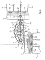
- Fig. 2 illustrates the compact design of the transmission according to the invention.
- Both machine beams 3 and the transmission according to the invention are arranged on a machine frame 26, which is usually attached via a three-point suspension to a towing vehicle.
- a machine beam 3 for this purpose is not attached via the pivotable part 2 of the transmission, but also held by its own flanges 28 of the machine frame 26.
- the transmission housing 30 in the region of the shaft ends of the intermediate shafts 17 guide walls 31 into which an axle 29 engages in register, whereby the pivoting of the machine beam 3 and the pivotable gear parts 2 is supported by identical axes of rotation 27 ( Fig. 3 ).
- the transmission used in the invention is compact and yet designed to save space, so that all the requirements for a durable transmission are met at low material costs.
- the angled section through the gearbox according to Fig. 3 shows in particular the dimensioning of the output shafts with the gears thereon, which are each designed for a permanent operation.
- a shift gear stage can be provided. This is advantageously operated by means of an actuating means also from outside the transmission and further increases the flexibility of the transmission according to the invention.
- the drive shaft 7, and the two transmission shafts 11 and 13 are mounted in the rigid main transmission part 1 and are lubricated from a common stock.
- the drive shaft 7 proximal edge 34 to which the Desiraddeckel 32 is applied pulled higher, so that a kind of well is formed in the Retirement the oil collects.
- both the interior of the rigid gear part 1 and the interior of the pivotable gear part 2 in the transition region with seals 36 are sealed.
- the output flange 18 sits snugly in a corresponding inner recess of the machine beam tray 37, wherein the dimensions are selected so that possibly using a further seal and the lubricants located in the machine beam tray 37 can not escape.
- the transmission is used according to the invention for a rotary harrow, since in this the requirements for the available drive forces are relatively large and the inventive transmission due to the compact design meets these requirements.
Landscapes
- Life Sciences & Earth Sciences (AREA)
- Engineering & Computer Science (AREA)
- Mechanical Engineering (AREA)
- Soil Sciences (AREA)
- Environmental Sciences (AREA)
- Soil Working Implements (AREA)
- General Details Of Gearings (AREA)
Claims (17)
- Transmission destinée à une machine de travail du sol comportant au moins une poutre (3) équipée d'un ensemble d'outils de travail (21, 22, 23) pouvant être positionnée dans une position de travail orientée transversalement par rapport à la direction de déplacement, et pouvant être reliée à un châssis (26) ainsi que d'une partie de transmission principale rigide pouvant être montée sur le châssis d'un arbre d'entrainement (7) monté dans celle-ci, et d'au moins un arbre de sortie (10) pouvant être mise en prise avec celui-ci,
caractérisée en ce que
les éléments d'entrainement rotatifs transmettant la force sont essentiellement montés à la partie interne, du carter de la transmission, une partie (2) de la transmission entourant au moins partiellement la roue de sortie (10) pouvant être déplacée par pivotement avec la poutre (3) montée sur celle-ci de la position de travail dans une position de déplacement verticales, et la partie pivotante (2) de la transmission comporte un arbre intermédiaire (17) autour de l'axe de rotation (27) duquel l'arbre de sortie et la poutre (3) pivotent. - Transmission conforme à la revendication 1,
caractérisée en ce que
l'arbre de sortie (10) vient en prise essentiellement verticalement dans la poutre (3). - Transmission conforme à l'une des revendications 1 et 2,
caractérisée en ce que
la partie pivotante (2) de la transmission présente un étage à roue conique par lequel l'arbre intermédiaire (17) est relié à l'arbre de sortie (10). - Transmission conforme à la revendication 3,
caractérisée en ce que
l'arbre de sortie (10) n'entraine qu'indirectement le premier outil de travail (22) le plus proche de l'arbre d'entrainement (7). - Transmission conforme à la revendication 4,
caractérisée en ce que
l'arbre de sortie (10) entraine les autres outils de travail (22, 23) par l'intermédiaire du second ou du troisième outil (21). - Transmission conforme à l'une des revendications 1 à 5,
caractérisée en ce que
l'arbre de sortie (10) entraine les outils de travail (21, 22, 23) par l'intermédiaire d'un étage de démultiplication dans la poutre (3) de la machine. - Transmission conforme à la revendication 6,
caractérisée en ce que
pour permettre l'utilisation de roues dentées (24) de différente dimension, l'arbre de sortie (10) peut être déplacé dans la poutre (3) parallèlement à son axe de rotation (20). - Transmission conforme à l'une des revendications 1 à 7,
caractérisée en ce que
la partie pivotante (2) de la transmission vient en prise dans la poutre (3) par l'intermédiaire d'une bride de guidage (18). - Transmission conforme à l'une des revendications 1 à 8,
caractérisée en ce que
l'arbre de sortie (10) et la poutre (3) peuvent être déplacés par pivotement d'environ 90°. - Transmission conforme à l'une des revendications 1 à 9,
caractérisée en ce que
la partie pivotante (2) de la transmission est montée d'une part sur la partie fixe (1) de la transmission et d'autre part sur le châssis (3) de la machine. - Transmission conforme à l'une des revendications 1 à 10,
caractérisée en ce que
pour permettre le centrage de la partie pivotante (2) de la transmission il est prévu au moins un tourillon d'axe (29). - Transmission conforme à la revendication 11,
caractérisée en ce que
la poutre (3) et la transmission s'appuient par l'intermédiaire du tourillon d'axe (29) contre le châssis (26) de la machine. - Transmission conforme à l'une des revendications 1 à 12,
caractérisée par
au moins un étage à roue de changement de vitesse. - Transmission conforme à la revendication 13,
caractérisée en ce que
l'étage à roue de changement de vitesse est un étage à roue de changement de vitesse frontale. - Transmission conforme à l'une des revendications 1 à 12,
caractérisée par
un étage de boite de vitesse. - Transmission conforme à l'une des revendications 1 à 15, pouvant être actionnée par une prise de force d'un véhicule tracteur,
caractérisée en ce que
l'arbre d'entrainement (7) de la transmission est monté essentiellement en alignement avec l'axe de la prise de force. - Herse rotative,
caractérisée par
une transmission conforme à l'une des revendications précédentes.
Applications Claiming Priority (1)
| Application Number | Priority Date | Filing Date | Title |
|---|---|---|---|
| DE200510009767 DE102005009767A1 (de) | 2005-03-03 | 2005-03-03 | Getriebe für Bodenbearbeitungsmaschine |
Publications (2)
| Publication Number | Publication Date |
|---|---|
| EP1698219A1 EP1698219A1 (fr) | 2006-09-06 |
| EP1698219B1 true EP1698219B1 (fr) | 2013-05-22 |
Family
ID=36588834
Family Applications (1)
| Application Number | Title | Priority Date | Filing Date |
|---|---|---|---|
| EP20060004351 Expired - Lifetime EP1698219B1 (fr) | 2005-03-03 | 2006-03-03 | Transmission pour machine de travail du sol |
Country Status (2)
| Country | Link |
|---|---|
| EP (1) | EP1698219B1 (fr) |
| DE (1) | DE102005009767A1 (fr) |
Families Citing this family (3)
| Publication number | Priority date | Publication date | Assignee | Title |
|---|---|---|---|---|
| DE202010002275U1 (de) * | 2010-02-12 | 2011-08-26 | Alois Pöttinger Maschinenfabrik Gmbh | Landmaschine |
| DE102012108852A1 (de) | 2012-09-20 | 2014-05-28 | Amazonen-Werke H. Dreyer Gmbh & Co. Kg | Bodenbearbeitungsmaschine |
| EP2959760B1 (fr) | 2012-09-20 | 2016-06-22 | Amazonen-Werke H. Dreyer GmbH & Co. KG | Machine de traitement de sol |
Family Cites Families (11)
| Publication number | Priority date | Publication date | Assignee | Title |
|---|---|---|---|---|
| CH330021A (de) | 1953-08-24 | 1958-05-31 | Meili Ernst | Mit einem Traktor verbundene Drehhacke |
| DE1943011A1 (de) * | 1969-08-23 | 1971-04-01 | Amazonen Werke Dreyer H | Bodenbearbeitungsgeraet mit bewegbar angeordneten Bodenbearbeitungswerkzeugen |
| NL178473B (nl) | 1974-09-03 | 1985-11-01 | Lely Nv C Van Der | Grondbewerkingsmachine. |
| DE8114520U1 (de) * | 1981-05-16 | 1982-02-04 | Amazonen-Werke H. Dreyer Gmbh & Co Kg, 4507 Hasbergen | "Landmaschine" |
| DE3628605A1 (de) | 1986-08-22 | 1988-02-25 | Fella Werke Gmbh | Heuwerbungsmaschine |
| DE3629774A1 (de) * | 1986-09-02 | 1988-03-03 | Rabewerk Clausing Heinrich | Getriebebausatz fuer ein zahnradgetriebe einer zapfwellengetriebenen bodenbearbeitungsmaschine |
| IT1220743B (it) | 1988-03-15 | 1990-06-21 | Maschio Spa | Macchina agricola per la lavorazione del suolo |
| NL9001873A (nl) * | 1990-08-24 | 1992-03-16 | Lely Nv C Van Der | Grondbewerkingsmachine. |
| DE4114342C2 (de) | 1991-05-02 | 1994-04-14 | Heissenberger & Pretzler Gmbh | Landmaschine, insbesondere Kreiselheuwerbungsmaschine |
| EP0548720A2 (fr) | 1991-12-21 | 1993-06-30 | Maschinenfabrik Bernard Krone GmbH | Machine de fenaison |
| DE10203067B4 (de) | 2002-01-28 | 2009-12-03 | Gkn Walterscheid Gmbh | Getriebeanordnung |
-
2005
- 2005-03-03 DE DE200510009767 patent/DE102005009767A1/de not_active Withdrawn
-
2006
- 2006-03-03 EP EP20060004351 patent/EP1698219B1/fr not_active Expired - Lifetime
Also Published As
| Publication number | Publication date |
|---|---|
| EP1698219A1 (fr) | 2006-09-06 |
| DE102005009767A1 (de) | 2006-09-14 |
Similar Documents
| Publication | Publication Date | Title |
|---|---|---|
| DE69010845T2 (de) | Mähmaschine mit einer sich quer zur Fahrtrichtung erstreckenden Arbeitswerkzeugeeinheit. | |
| EP0277343B1 (fr) | Faucheuse | |
| DE69608193T2 (de) | Heuwerbungsmaschine | |
| DE3628605C2 (fr) | ||
| DE2858680C2 (fr) | ||
| DE68904246T2 (de) | Landmaschine mit mindestens einem waehrend der arbeit angetriebenen rechrad. | |
| DE2843782C2 (de) | Kreiselheuwerbungsmaschine zum Schwadenlegen oder Schwadenwenden oder zum Zetten/Wenden | |
| DE2800500A1 (de) | Kreiselmaeher | |
| DE3218385C2 (fr) | ||
| DE4322263C5 (de) | Verfahren zur Vorbereitung eines auf einer Bodenfläche fahrenden Arbeitsfahrzeuges mit einem Arbeitsgerät für den Straßenbetrieb und Arbeitsgerät zur Anordnung an einem solchen Arbeitsfahrzeug | |
| DE69403511T2 (de) | Heuwerbungsmaschine | |
| EP1698219B1 (fr) | Transmission pour machine de travail du sol | |
| EP3725147A1 (fr) | Faucheuse | |
| DE3436123C2 (de) | Kreiselegge | |
| EP1574750B1 (fr) | Transmission | |
| EP0291812A1 (fr) | Machine agricole, en particulier un épandeur d'herbe à disque | |
| EP1295520B1 (fr) | Herse rotative à entrainement du rotor amélioré | |
| DE2624523A1 (de) | Bodenbearbeitungsgeraet | |
| DE69512559T2 (de) | Heuwerbungsmaschine, insbesondere ein Schwader für Futter | |
| DE69304558T2 (de) | Heuwerbungsmaschine mit einem mit gesteuerten Stützrädern versehenen Rahmen | |
| DE1942375C3 (de) | Schürfkübelfahrzeug mit einem Kratzerkettenförderer | |
| DE69417689T2 (de) | Heuwerbungsmaschine | |
| DE69412756T2 (de) | Heuwerbungsmaschine | |
| DE69604317T2 (de) | Heuwerbungsmaschine | |
| EP0532492B1 (fr) | Charrue comportant un dispositif d'entraînement |
Legal Events
| Date | Code | Title | Description |
|---|---|---|---|
| PUAI | Public reference made under article 153(3) epc to a published international application that has entered the european phase |
Free format text: ORIGINAL CODE: 0009012 |
|
| AK | Designated contracting states |
Kind code of ref document: A1 Designated state(s): AT BE BG CH CY CZ DE DK EE ES FI FR GB GR HU IE IS IT LI LT LU LV MC NL PL PT RO SE SI SK TR |
|
| AX | Request for extension of the european patent |
Extension state: AL BA HR MK YU |
|
| 17P | Request for examination filed |
Effective date: 20070223 |
|
| 17Q | First examination report despatched |
Effective date: 20070330 |
|
| AKX | Designation fees paid |
Designated state(s): DE FR GB IT |
|
| RAP1 | Party data changed (applicant data changed or rights of an application transferred) |
Owner name: ROEGELBERG HOLDING GMBH & CO. KG |
|
| GRAP | Despatch of communication of intention to grant a patent |
Free format text: ORIGINAL CODE: EPIDOSNIGR1 |
|
| GRAS | Grant fee paid |
Free format text: ORIGINAL CODE: EPIDOSNIGR3 |
|
| GRAA | (expected) grant |
Free format text: ORIGINAL CODE: 0009210 |
|
| AK | Designated contracting states |
Kind code of ref document: B1 Designated state(s): DE FR GB IT |
|
| REG | Reference to a national code |
Ref country code: GB Ref legal event code: FG4D Free format text: NOT ENGLISH |
|
| REG | Reference to a national code |
Ref country code: DE Ref legal event code: R096 Ref document number: 502006012861 Country of ref document: DE Effective date: 20130718 |
|
| PLBI | Opposition filed |
Free format text: ORIGINAL CODE: 0009260 |
|
| PLAX | Notice of opposition and request to file observation + time limit sent |
Free format text: ORIGINAL CODE: EPIDOSNOBS2 |
|
| 26 | Opposition filed |
Opponent name: AMAZONEN-WERKE H. DREYER GMBH & CO. KG Effective date: 20140221 |
|
| REG | Reference to a national code |
Ref country code: DE Ref legal event code: R026 Ref document number: 502006012861 Country of ref document: DE Effective date: 20140221 |
|
| PLAF | Information modified related to communication of a notice of opposition and request to file observations + time limit |
Free format text: ORIGINAL CODE: EPIDOSCOBS2 |
|
| PLBB | Reply of patent proprietor to notice(s) of opposition received |
Free format text: ORIGINAL CODE: EPIDOSNOBS3 |
|
| PLBP | Opposition withdrawn |
Free format text: ORIGINAL CODE: 0009264 |
|
| GBPC | Gb: european patent ceased through non-payment of renewal fee |
Effective date: 20140303 |
|
| PLBD | Termination of opposition procedure: decision despatched |
Free format text: ORIGINAL CODE: EPIDOSNOPC1 |
|
| PG25 | Lapsed in a contracting state [announced via postgrant information from national office to epo] |
Ref country code: GB Free format text: LAPSE BECAUSE OF NON-PAYMENT OF DUE FEES Effective date: 20140303 |
|
| PLBM | Termination of opposition procedure: date of legal effect published |
Free format text: ORIGINAL CODE: 0009276 |
|
| STAA | Information on the status of an ep patent application or granted ep patent |
Free format text: STATUS: OPPOSITION PROCEDURE CLOSED |
|
| 27C | Opposition proceedings terminated |
Effective date: 20140912 |
|
| REG | Reference to a national code |
Ref country code: FR Ref legal event code: PLFP Year of fee payment: 11 |
|
| REG | Reference to a national code |
Ref country code: FR Ref legal event code: PLFP Year of fee payment: 12 |
|
| REG | Reference to a national code |
Ref country code: FR Ref legal event code: PLFP Year of fee payment: 13 |
|
| PGFP | Annual fee paid to national office [announced via postgrant information from national office to epo] |
Ref country code: DE Payment date: 20250120 Year of fee payment: 20 |
|
| PGFP | Annual fee paid to national office [announced via postgrant information from national office to epo] |
Ref country code: FR Payment date: 20250324 Year of fee payment: 20 |
|
| PGFP | Annual fee paid to national office [announced via postgrant information from national office to epo] |
Ref country code: IT Payment date: 20250331 Year of fee payment: 20 |
|
| REG | Reference to a national code |
Ref country code: DE Ref legal event code: R071 Ref document number: 502006012861 Country of ref document: DE |