EP1698281A1 - Sonde à ultrasons - Google Patents
Sonde à ultrasons Download PDFInfo
- Publication number
- EP1698281A1 EP1698281A1 EP06004247A EP06004247A EP1698281A1 EP 1698281 A1 EP1698281 A1 EP 1698281A1 EP 06004247 A EP06004247 A EP 06004247A EP 06004247 A EP06004247 A EP 06004247A EP 1698281 A1 EP1698281 A1 EP 1698281A1
- Authority
- EP
- European Patent Office
- Prior art keywords
- cap
- ultrasonic
- density
- low
- ultrasonic probe
- Prior art date
- Legal status (The legal status is an assumption and is not a legal conclusion. Google has not performed a legal analysis and makes no representation as to the accuracy of the status listed.)
- Granted
Links
- 239000000523 sample Substances 0.000 title claims abstract description 34
- 230000000694 effects Effects 0.000 claims abstract description 4
- 239000000463 material Substances 0.000 claims description 24
- 239000007788 liquid Substances 0.000 claims description 9
- 238000004804 winding Methods 0.000 claims description 3
- XLYOFNOQVPJJNP-UHFFFAOYSA-N water Substances O XLYOFNOQVPJJNP-UHFFFAOYSA-N 0.000 abstract description 20
- 229920005989 resin Polymers 0.000 description 8
- 239000011347 resin Substances 0.000 description 8
- 230000035945 sensitivity Effects 0.000 description 7
- 238000003780 insertion Methods 0.000 description 6
- 230000037431 insertion Effects 0.000 description 6
- 239000004698 Polyethylene Substances 0.000 description 4
- 238000005259 measurement Methods 0.000 description 4
- -1 polyethylene Polymers 0.000 description 4
- 229920000573 polyethylene Polymers 0.000 description 4
- HFGPZNIAWCZYJU-UHFFFAOYSA-N lead zirconate titanate Chemical compound [O-2].[O-2].[O-2].[O-2].[O-2].[Ti+4].[Zr+4].[Pb+2] HFGPZNIAWCZYJU-UHFFFAOYSA-N 0.000 description 2
- 229910052451 lead zirconate titanate Inorganic materials 0.000 description 2
- 230000007246 mechanism Effects 0.000 description 2
- 238000012986 modification Methods 0.000 description 2
- 230000004048 modification Effects 0.000 description 2
- FAPWRFPIFSIZLT-UHFFFAOYSA-M Sodium chloride Chemical compound [Na+].[Cl-] FAPWRFPIFSIZLT-UHFFFAOYSA-M 0.000 description 1
- 230000004075 alteration Effects 0.000 description 1
- 230000005540 biological transmission Effects 0.000 description 1
- 230000008859 change Effects 0.000 description 1
- 238000003745 diagnosis Methods 0.000 description 1
- 239000003822 epoxy resin Substances 0.000 description 1
- 238000000034 method Methods 0.000 description 1
- 239000002121 nanofiber Substances 0.000 description 1
- 230000000149 penetrating effect Effects 0.000 description 1
- 230000035515 penetration Effects 0.000 description 1
- 229920000647 polyepoxide Polymers 0.000 description 1
- 238000011160 research Methods 0.000 description 1
- 238000007789 sealing Methods 0.000 description 1
- 239000011780 sodium chloride Substances 0.000 description 1
- 238000012360 testing method Methods 0.000 description 1
- 239000010409 thin film Substances 0.000 description 1
- 238000003325 tomography Methods 0.000 description 1
- 229910000859 α-Fe Inorganic materials 0.000 description 1
Images


Classifications
-
- A—HUMAN NECESSITIES
- A61—MEDICAL OR VETERINARY SCIENCE; HYGIENE
- A61B—DIAGNOSIS; SURGERY; IDENTIFICATION
- A61B8/00—Diagnosis using ultrasonic, sonic or infrasonic waves
- A61B8/44—Constructional features of the ultrasonic, sonic or infrasonic diagnostic device
- A61B8/4444—Constructional features of the ultrasonic, sonic or infrasonic diagnostic device related to the probe
- A61B8/445—Details of catheter construction
-
- A—HUMAN NECESSITIES
- A61—MEDICAL OR VETERINARY SCIENCE; HYGIENE
- A61B—DIAGNOSIS; SURGERY; IDENTIFICATION
- A61B8/00—Diagnosis using ultrasonic, sonic or infrasonic waves
- A61B8/12—Diagnosis using ultrasonic, sonic or infrasonic waves in body cavities or body tracts, e.g. by using catheters
-
- A—HUMAN NECESSITIES
- A61—MEDICAL OR VETERINARY SCIENCE; HYGIENE
- A61B—DIAGNOSIS; SURGERY; IDENTIFICATION
- A61B8/00—Diagnosis using ultrasonic, sonic or infrasonic waves
- A61B8/44—Constructional features of the ultrasonic, sonic or infrasonic diagnostic device
- A61B8/4444—Constructional features of the ultrasonic, sonic or infrasonic diagnostic device related to the probe
- A61B8/4461—Features of the scanning mechanism, e.g. for moving the transducer within the housing of the probe
Definitions
- the present invention relates to an ultrasonic probe which scans inside a living organism by ultrasonic, with use of an ultrasonic transducer.
- the ultrasonic image is obtained by emitting ultrasonic waves to a required area of a living organism from an ultrasonic probe, and electrically detecting echo signal reflected from the living organism.
- an ultrasonic tomography can be obtained.
- an ultrasonic probe having a scanning mechanism for mechanically rotating, swinging or sliding an ultrasonic transducer which transmits/receives the ultrasonic waves.
- an operator inserts the ultrasonic probe into a forceps inlet of an endoscope, and follows the position of a leading end of the ultrasonic probe in the living organism by use of a camera provided at leading edge of the endoscope.
- the ultrasonic transducer includes a piezoelectric element, electrodes and an acoustic matching layer, and is contained in a cap for sealing the leading end of the ultrasonic probe.
- the cap is filled with suitable liquid so as to improve a transmission efficiency of the ultrasonic waves and to smooth the movement of the ultrasonic transducer (for example Japanese Patent Laid-Open Publication No. 2002-345819).
- the cap is also essential for protecting the moving ultrasonic transducer.
- the cap is formed of a resin material, such as polyethylene.
- the resin has high acoustic impedance which cannot match that of the living organism, which lowers receiver sensitivity of the ultrasonic transducer.
- One solution for matching the acoustic impedance between the cap and the living organism is to change the material used for the cap.
- a new resin material as an alteration of known current resin material, an enormous cost and work is needed to research and test the new material so as to confirm biocompatibility thereof. Accordingly, the use of new material is not practical.
- a main object of the present invention is to provide an ultrasonic probe which has improved receiver sensitivity with using a general material for a cap.
- an ultrasonic probe of the present invention comprises an ultrasonic transducer for sending and/or receiving ultrasonic waves to and/or from a living organism and a cap for covering the ultrasonic transducer while transmitting the ultrasonic waves, and the cap includes a high- and low-density area where low material density parts and high material density parts are alternately formed for transmitting the ultrasonic waves.
- a density interval of the high- and low-density area is smaller than a wavelength of the ultrasonic wave.
- the low material density part is an opening.
- liquid is supplied into the cap and then flows outside the cap through the openings.
- the ultrasonic probe further comprises a balloon attached to the cap for covering the openings, and the liquid flows into the balloon through inside the cap and the openings.
- the high- and low-density area is formed by winding a wire around a frame.
- the low material density part is a concave.
- the density interval is constant across the high- and low-density area.
- the density interval is not constant but changed in the high- and low-density area to give different acoustic impedances at different places in the high- and low-density area.
- the cap has a cylindrical shape and the density interval is gradually changed in an axial direction and/or a circumference direction of the cap.
- the density interval is gradually changed from a center toward ends in the axial direction of the cap such that the acoustic impedance gradually becomes higher from the center toward the ends, so as to give an acoustic lens effect to the cap in the axial direction.
- the cap since the cap includes the high- and low-density area where the low material density parts and high material density parts are alternately formed for transmitting the ultrasonic waves, and the density interval of the high- and low-density area is smaller than the wavelength of the ultrasonic wave, the high- and low-density area is deemed to have a uniform acoustic impedance to the ultrasonic waves, reducing the acoustic impedance of the cap. Accordingly, a consistency of the acoustic impedances between the cap and the living organism is improved so that a receiver sensitivity of the ultrasonic transducer is increased. In addition, such cap can be easily formed of a conventional resin material with low cost.
- the balloon Since the low material density part is the opening, the balloon is attached to the cap for covering the openings, and the liquid flows into the balloon through inside the cap and the openings, a conventional dedicated liquid supply line to the balloon is not needed. Accordingly, the ultrasonic probe can be downsized.
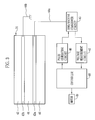
- an ultrasonic diagnosing system 2 is composed of an endoscope 10, ultrasonic probe 11 and an ultrasonic observer 12.
- the endoscope 10 comprises a flexible insertion section 13 for being inserted into a living organism, an operation section 14 connected to a tail end of the insertion section 13, and a cord 15 connecting between the operation section 14 and a processor for endoscope (not shown).
- a camera (not shown) for capturing images of inside the living organism is incorporated. The image captured by the camera is displayed on a monitor for endoscope (not shown) through the processor for endoscope.
- the ultrasonic probe 11 is composed of a flexible sheath 17 for penetrating the insertion section 13 from a forceps inlet 16 of the endoscope 10, a translator 18 incorporating a motor 49 and other members (refer to FIG.3) described later, and a cord 19 connecting between the translator 18 and the ultrasonic observer 12.
- the ultrasonic observer 12 has a monitor 20 for displaying an ultrasonic image.
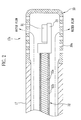
- a cylindrical cap 30 formed of a resin material such as polyethylene is attached at a leading end 17a of the sheath 17.
- plural holes (openings) 30a are provided in an area where the ultrasonic waves passing through.
- the cap 30 covers an ultrasonic transducer 31, and a water inlet (not shown) is provided at a tail end of the sheath 17.
- the ultrasonic transducer 31 is attached on a base 33 to which a control cable 32 is connected.
- the control cable 32 is composed of a flexible shaft 32a and a flexible tube 32b for covering the flexible shaft 32a.
- a leading end of the flexible shaft 32a is connected to the base 33, and a tail end of the shaft 32a is inside the translator 18.
- the flexible shaft 32a is rotated at a predetermined revolution speed (for example 10 to 40 rolls per second) by the motor 49 (refer to FIG.3). Accordingly, the ultrasonic transducer 31 is rotated at the predetermined revolution speed around the flexible shaft 32a as a rotational axis. Note that since the water inside the cap 30 always flows, generation of air bubbles (cavitation) by the rotation of the ultrasonic transducer 31 is prevented.
- the ultrasonic transducer 31 comprises a backing plate 40 formed of ferrite rubber, a piezoelectric element 41 formed of thin film of PZT (lead zirconate titanate) and an acoustic matching layer 42 formed of epoxy resin, which are laminated on the base 33 in this order.
- the piezoelectric element 41 is sandwiched between electrodes 43a and 43b.
- wires 44a and 44b are connected to the respective electrodes 43a and 43b.
- the other side of the wire 44b for the electrode 43b is connected to earth.
- the other side of the wire 44a for the electrode 43a is connected to a send/receive changeover circuit 45 in the translator 18 through the control cable 32.
- the send/receive changeover circuit 45 alternatively changes the ultrasonic transducer 31 to send or receive the ultrasonic waves at predetermined intervals.
- a pulse generating circuit 46 and a voltage measurement circuit 47 is connected to the send/receive changeover circuit 45.
- the pulse generating circuit 46 applies a pulse voltage to the piezoelectric element 41 when the ultrasonic transducer 31 is going to generate the ultrasonic waves (the sending of ultrasonic wave). Thereby, the ultrasonic transducer 31 will generate the ultrasonic waves having a specific frequency.
- the voltage measurement circuit 47 measures a voltage generated in the piezoelectric element 41 when the ultrasonic transducer 31 receives an echo signal from the living organism (the receiving of ultrasonic wave).
- the voltage measurement circuit 47 sends a measuring result to a controller 48.
- the controller 48 converts the received measuring result into an ultrasonic image, and sends this ultrasonic image to the ultrasonic observer 12.
- the ultrasonic probe 11 is inserted from the forceps inlet 16 to penetrate the insertion section 13 of the endoscope 10. Then the insertion section 13 is inserted in the living organism. An operator searches a required area of the living organism with observing the monitor for endoscope. When the leading end 17a of the sheath 17 reaches at the required area, the water is supplied inside the sheath 17, flows out of the cap 30 through the holes 30a, and fills the required area.
- the ultrasonic transducer 31 rotates at the predetermined revolution speed. At the same time, the ultrasonic transducer 31 generates the ultrasonic waves by the application of the pulse voltage from the pulse generating circuit 46, while the send/receive changeover circuit 45 alternatively changes the ultrasonic transducer 31 to send or receive the ultrasonic waves at predetermined intervals.
- the living organism is scanned with the ultrasonic waves passing through the cap 30.
- the voltage measurement circuit 47 measures the voltage generated in the piezoelectric element 41.
- the rectangular holes 30a are arranged in the cap 30 at regular intervals.
- a meshed area where the holes 30a are arranged is a high- and low-density area where low material density parts (holes 30a) and high material density parts (between the adjacent holes 30a) are alternately formed.
- the ultrasonic waves from/to the ultrasonic transducer 31 pass through this high- and low-density area.
- a density interval d (pitch of holes 30a) is sufficiently smaller than a shortest wavelength ⁇ of the ultrasonic waves, preferably below 5% of the wavelength ⁇ (d ⁇ 0.05), more preferably below 1% of the wavelength ⁇ (d ⁇ 0.01).
- the ultrasonic waves when a center frequency thereof is 7.5MHz, and a band thereof is 90% of the center frequency, a bandwidth is 4 to 11MHz. Since a sonic velocity v in water is approximately 1500m/s, the shortest wavelength ⁇ of the ultrasonic waves is calculated to (1500m/s) ⁇ (11MHz) ⁇ 136 ⁇ m. In this case, the density interval d is preferably below 6.8 ⁇ m, more preferably below 1.4 ⁇ m. Note that a length of one side of the hole 30a is approximately equal to the pitch of the holes.
- the high- and low-density area is deemed uniform to the ultrasonic wave because an amplitude, a phase and a velocity of the ultrasonic wave are not affected.
- the acoustic impedance of the cap 30 is reduced from when there is no hole 30a (there is no high- and low-density area). Accordingly, a consistency of the acoustic impedances between the cap 30 and the living organism is improved, an ultrasonic reflectance of the cap 30 is lowered, and a receiver sensitivity of the ultrasonic transducer 31 is increased.
- the acoustic impedance of the cap 30 can be reduced by reducing the density of the meshed area (a proportion of the high density parts).
- the cap 30 is formed of a polyethylene having approximately 2.3Mrayl of the acoustic impedance
- the water having approximately 1.5Mrayl of the acoustic impedance fills the holes 30a (low density parts) and the density of the meshed area is 20 to 30%
- the acoustic impedance of the meshed area of the cap 30 becomes approximately 1.7Mrayl.
- the receiver sensitivity is increased approximately 6 to 7dB from when the density of the meshed area is 100% (there is no hole 30a).
- the meshed area of the cap 30 can be formed by winding a wire 51 around a lattice-shaped frame 50.
- the frame 50 is formed of a resin material such as polyethylene having approximately 100 ⁇ m thickness.
- nanofiber for example, dtx44 of Toray Industries, Inc.
- each rectangular opening in the frame 50 preferably has one side of few millimeters (approximately 2mm to 3mm) or more length, to prevent generation of sidelobe by diffraction.
- the cap 30 can be easily formed of conventional resin material with low cost, while improving the consistency of the acoustic impedances between the cap 30 and the living organism. Accordingly, the receiver sensitivity of the ultrasonic transducer 31 is increased, a penetration of the obtained image is increased, and the performance of the ultrasonic diagnosing system 2 is improved.
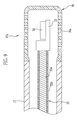
- an elastic balloon 52 is attached to the cap 30 so as to cover the meshed area.
- the water flows through the water inlet of the sheath 17, inside the sheath 17 and inside the cap 30.
- the balloon 52 expands according to an amount of entered water, to push the required portion in the living organism when the leading end 17a of the sheath 17 reaches the required portion.
- a conventional dedicated water supply line to the balloon 52 is not needed, because the sheath 17 and the cap 30 are worked as the water supply line.
- the hole 30a of the cap 30 has the rectangular shape.
- the shape of the hole 30a is not limited in the present invention, and any other shapes, for example a circular shape and a slit shape, can be applied.
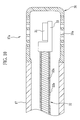
- concaves 30b can be formed as alternative to the holes 30a.
- the concave 30b becomes the low density part in the high- and low-density area.
- a density interval pitch of concaves 30b
- the high- and low-density area is deemed uniform to the ultrasonic wave.
- the acoustic impedance of the cap 30 is reduced from when there is no concave 30b. In this embodiment, the water from the sheath 17 stays inside the cap 30.
- the low density parts are arranged at regular intervals, to give the constant acoustic impedance to whole of the high- and low-density area.
- the density interval is uneven in the high- and low-density area to give different acoustic impedances at different places in the high- and low-density area.
- the interval between the low density parts gradually becomes larger from a center toward ends in an axial direction of the cap 30.
- the width of the each hole 30a (interval between the high density parts) gradually becomes smaller from the center toward the ends in the axial direction of the cap 30.
- the acoustic impedance gradually becomes higher from the center, which corresponds to a center of the ultrasonic transducer 31, toward the ends in the axial direction. Accordingly, the cap 30 acts as an acoustic lens, which can focus the ultrasonic waves from the ultrasonic transducer 31 in the axial direction.
- the interval or width of the holes 30a is gradually changed in the circumference direction of the cap 30, to give the acoustic lens effect to the cap 30 in the circumference direction.
- the ultrasonic waves can be focused in the rotational direction of the ultrasonic transducer 31, which improves an azimuth resolution.
- the high- and low-density area is formed only in a region of the cap 30 which the ultrasonic waves pass through.
- the high- and low-density area is formed in whole of the cap 30.
- the supplying liquid is not limited to the water.
- Another liquid such as a saline or the like, can be used as an alternative to the water.
- the ultrasonic probe 11 has the ultrasonic transducer which rotates around the flexible shaft 32a as the rotational axis.
- the present invention can be applied to an ultrasonic probe having the ultrasonic transducer which swings or slides to scan the living organism.
- the ultrasonic transducer 31 sends and receives the ultrasonic.
- the present invention can be applied to an ultrasonic transducer which can only send or receive the ultrasonic.
Landscapes
- Life Sciences & Earth Sciences (AREA)
- Health & Medical Sciences (AREA)
- Biomedical Technology (AREA)
- Biophysics (AREA)
- Nuclear Medicine, Radiotherapy & Molecular Imaging (AREA)
- Pathology (AREA)
- Radiology & Medical Imaging (AREA)
- Engineering & Computer Science (AREA)
- Physics & Mathematics (AREA)
- Heart & Thoracic Surgery (AREA)
- Medical Informatics (AREA)
- Molecular Biology (AREA)
- Surgery (AREA)
- Animal Behavior & Ethology (AREA)
- General Health & Medical Sciences (AREA)
- Public Health (AREA)
- Veterinary Medicine (AREA)
- Ultra Sonic Daignosis Equipment (AREA)
Applications Claiming Priority (1)
| Application Number | Priority Date | Filing Date | Title |
|---|---|---|---|
| JP2005061156A JP4517239B2 (ja) | 2005-03-04 | 2005-03-04 | 超音波プローブ |
Publications (2)
| Publication Number | Publication Date |
|---|---|
| EP1698281A1 true EP1698281A1 (fr) | 2006-09-06 |
| EP1698281B1 EP1698281B1 (fr) | 2009-07-29 |
Family
ID=36217610
Family Applications (1)
| Application Number | Title | Priority Date | Filing Date |
|---|---|---|---|
| EP06004247A Expired - Fee Related EP1698281B1 (fr) | 2005-03-04 | 2006-03-02 | Sonde à ultrasons |
Country Status (4)
| Country | Link |
|---|---|
| US (1) | US20060241472A1 (fr) |
| EP (1) | EP1698281B1 (fr) |
| JP (1) | JP4517239B2 (fr) |
| DE (1) | DE602006008052D1 (fr) |
Cited By (1)
| Publication number | Priority date | Publication date | Assignee | Title |
|---|---|---|---|---|
| WO2021095899A1 (fr) * | 2019-11-11 | 2021-05-20 | 재단법인 파동에너지 극한제어연구단 | Unité de couvercle à transmission sonore élevée de transducteur à ultrasons |
Families Citing this family (5)
| Publication number | Priority date | Publication date | Assignee | Title |
|---|---|---|---|---|
| US8248888B1 (en) * | 2010-08-04 | 2012-08-21 | Measurement Specialties, Inc. | Bottom up contact type ultrasonic continuous level sensor |
| JP5253691B1 (ja) * | 2011-09-09 | 2013-07-31 | オリンパスメディカルシステムズ株式会社 | 超音波内視鏡 |
| JP6421277B2 (ja) * | 2015-05-15 | 2018-11-07 | ハジッチ、アドミル | 超音波プローブカバー及び使用方法 |
| WO2017096406A1 (fr) * | 2015-12-04 | 2017-06-08 | The Research Foundation For The State University Of New York | Dispositifs et procédés de tomographie photoacoustique |
| JP6608531B2 (ja) * | 2016-06-29 | 2019-11-20 | オリンパス株式会社 | 超音波内視鏡 |
Citations (5)
| Publication number | Priority date | Publication date | Assignee | Title |
|---|---|---|---|---|
| EP0466424A1 (fr) * | 1990-07-06 | 1992-01-15 | Cardiometrics, Inc. | Ensemble de fil de guidage avec connecteur électrique rotatif |
| US5400785A (en) * | 1994-02-03 | 1995-03-28 | Boston Scientific Corp. | Acoustic window and septum for imaging catheters |
| US5846205A (en) * | 1997-01-31 | 1998-12-08 | Acuson Corporation | Catheter-mounted, phased-array ultrasound transducer with improved imaging |
| EP0940123A2 (fr) * | 1992-02-21 | 1999-09-08 | Boston Scientific Corporation | Cathéter pour imagerie par ultrasons |
| US6689066B1 (en) * | 2001-12-05 | 2004-02-10 | Olympus Corporation | Ultrasonic probe |
Family Cites Families (9)
| Publication number | Priority date | Publication date | Assignee | Title |
|---|---|---|---|---|
| JP2675333B2 (ja) * | 1988-05-31 | 1997-11-12 | オリンパス光学工業株式会社 | 超音波内視鏡 |
| JP2798749B2 (ja) * | 1989-12-05 | 1998-09-17 | オリンパス光学工業株式会社 | 超音波プローブ |
| JP3782107B2 (ja) * | 1994-11-30 | 2006-06-07 | ボストン サイエンティフィック リミテッド | 音響像形成、ドプラーカテーテルおよびガイドワイヤ |
| US5762995A (en) * | 1995-01-13 | 1998-06-09 | Fuji Photo Optical Co., Ltd. | Flexible sheathing tube construction, and method for fabrication thereof |
| US5834687A (en) * | 1995-06-07 | 1998-11-10 | Acuson Corporation | Coupling of acoustic window and lens for medical ultrasound transducers |
| JPH10262972A (ja) * | 1997-03-24 | 1998-10-06 | Fuji Photo Optical Co Ltd | 超音波検査装置 |
| JP2001224595A (ja) * | 1999-12-08 | 2001-08-21 | Olympus Optical Co Ltd | 顕微鏡下手術用超音波プローブ |
| EP1453425B1 (fr) * | 2001-12-03 | 2006-03-08 | Ekos Corporation | Catheter a elements multiples rayonnants a ultrasons |
| WO2004010730A2 (fr) * | 2002-07-18 | 2004-01-29 | Measurement Specialties, Inc. | Transducteur a ultrasons pour dispositifs electroniques |
-
2005
- 2005-03-04 JP JP2005061156A patent/JP4517239B2/ja not_active Expired - Fee Related
-
2006
- 2006-03-02 DE DE602006008052T patent/DE602006008052D1/de not_active Expired - Lifetime
- 2006-03-02 EP EP06004247A patent/EP1698281B1/fr not_active Expired - Fee Related
- 2006-03-03 US US11/366,409 patent/US20060241472A1/en not_active Abandoned
Patent Citations (5)
| Publication number | Priority date | Publication date | Assignee | Title |
|---|---|---|---|---|
| EP0466424A1 (fr) * | 1990-07-06 | 1992-01-15 | Cardiometrics, Inc. | Ensemble de fil de guidage avec connecteur électrique rotatif |
| EP0940123A2 (fr) * | 1992-02-21 | 1999-09-08 | Boston Scientific Corporation | Cathéter pour imagerie par ultrasons |
| US5400785A (en) * | 1994-02-03 | 1995-03-28 | Boston Scientific Corp. | Acoustic window and septum for imaging catheters |
| US5846205A (en) * | 1997-01-31 | 1998-12-08 | Acuson Corporation | Catheter-mounted, phased-array ultrasound transducer with improved imaging |
| US6689066B1 (en) * | 2001-12-05 | 2004-02-10 | Olympus Corporation | Ultrasonic probe |
Cited By (2)
| Publication number | Priority date | Publication date | Assignee | Title |
|---|---|---|---|---|
| WO2021095899A1 (fr) * | 2019-11-11 | 2021-05-20 | 재단법인 파동에너지 극한제어연구단 | Unité de couvercle à transmission sonore élevée de transducteur à ultrasons |
| KR20210057288A (ko) * | 2019-11-11 | 2021-05-21 | 재단법인 파동에너지 극한제어 연구단 | 초음파 트랜스듀서의 음향 초투과형 커버 유닛 |
Also Published As
| Publication number | Publication date |
|---|---|
| JP2006239240A (ja) | 2006-09-14 |
| JP4517239B2 (ja) | 2010-08-04 |
| DE602006008052D1 (de) | 2009-09-10 |
| EP1698281B1 (fr) | 2009-07-29 |
| US20060241472A1 (en) | 2006-10-26 |
Similar Documents
| Publication | Publication Date | Title |
|---|---|---|
| JP5073276B2 (ja) | ボリューメトリック超音波用の回転可能なトランスデューサ・アレイ | |
| US11998396B2 (en) | Ultrasound diagnostic apparatus and operation method of ultrasound diagnostic apparatus | |
| JP4294376B2 (ja) | 超音波診断プローブ装置 | |
| JP3654309B2 (ja) | 針状超音波探触子 | |
| CN102293665B (zh) | 超声波诊断装置 | |
| JP6064098B1 (ja) | 超音波振動子および超音波プローブ | |
| JP4370120B2 (ja) | 超音波内視鏡および超音波内視鏡装置 | |
| JP2011050542A (ja) | 超音波診断装置 | |
| EP2979644A1 (fr) | Sonde ultrasonore pour aiguille de ponction et dispositif de diagnostic par ultrasons l'utilisant | |
| EP1698281B1 (fr) | Sonde à ultrasons | |
| CN115151194A (zh) | 超声波探头及超声波内窥镜 | |
| JP4074169B2 (ja) | 超音波送受信ユニット | |
| KR20190092781A (ko) | 초음파 프로브 | |
| JP2001238885A (ja) | 超音波探触子 | |
| CN105167808A (zh) | 一种经尿道的前列腺超声检测方法、诊断仪及换能器 | |
| WO2019151255A1 (fr) | Vibrateur à ultrasons et endoscope à ultrasons | |
| KR20110003056A (ko) | 초음파 프로브 및 초음파 진단장치 | |
| JPS62227334A (ja) | 超音波内視鏡 | |
| JP3631416B2 (ja) | 超音波プローブ | |
| JP7842770B2 (ja) | 超音波内視鏡システム、及び超音波内視鏡システムの作動方法 | |
| JP2007082629A (ja) | 超音波プローブ | |
| JP4560417B2 (ja) | 超音波トランスデューサ、およびその製造方法、並びに超音波プローブ | |
| JP5069610B2 (ja) | 超音波トランスデューサ及び超音波探触子 | |
| JP2006204617A (ja) | 超音波プローブ | |
| JP2006026232A (ja) | 超音波内視鏡 |
Legal Events
| Date | Code | Title | Description |
|---|---|---|---|
| PUAI | Public reference made under article 153(3) epc to a published international application that has entered the european phase |
Free format text: ORIGINAL CODE: 0009012 |
|
| AK | Designated contracting states |
Kind code of ref document: A1 Designated state(s): AT BE BG CH CY CZ DE DK EE ES FI FR GB GR HU IE IS IT LI LT LU LV MC NL PL PT RO SE SI SK TR |
|
| AX | Request for extension of the european patent |
Extension state: AL BA HR MK YU |
|
| 17P | Request for examination filed |
Effective date: 20061130 |
|
| RAP1 | Party data changed (applicant data changed or rights of an application transferred) |
Owner name: FUJINON CORPORATION Owner name: FUJIFILM CORPORATION |
|
| AKX | Designation fees paid |
Designated state(s): DE FR GB |
|
| 17Q | First examination report despatched |
Effective date: 20071119 |
|
| GRAP | Despatch of communication of intention to grant a patent |
Free format text: ORIGINAL CODE: EPIDOSNIGR1 |
|
| GRAS | Grant fee paid |
Free format text: ORIGINAL CODE: EPIDOSNIGR3 |
|
| GRAA | (expected) grant |
Free format text: ORIGINAL CODE: 0009210 |
|
| AK | Designated contracting states |
Kind code of ref document: B1 Designated state(s): DE FR GB |
|
| REG | Reference to a national code |
Ref country code: GB Ref legal event code: FG4D |
|
| REF | Corresponds to: |
Ref document number: 602006008052 Country of ref document: DE Date of ref document: 20090910 Kind code of ref document: P |
|
| PLBE | No opposition filed within time limit |
Free format text: ORIGINAL CODE: 0009261 |
|
| STAA | Information on the status of an ep patent application or granted ep patent |
Free format text: STATUS: NO OPPOSITION FILED WITHIN TIME LIMIT |
|
| 26N | No opposition filed |
Effective date: 20100503 |
|
| REG | Reference to a national code |
Ref country code: FR Ref legal event code: PLFP Year of fee payment: 10 |
|
| PGFP | Annual fee paid to national office [announced via postgrant information from national office to epo] |
Ref country code: DE Payment date: 20150224 Year of fee payment: 10 |
|
| PGFP | Annual fee paid to national office [announced via postgrant information from national office to epo] |
Ref country code: GB Payment date: 20150225 Year of fee payment: 10 Ref country code: FR Payment date: 20150309 Year of fee payment: 10 |
|
| REG | Reference to a national code |
Ref country code: DE Ref legal event code: R119 Ref document number: 602006008052 Country of ref document: DE |
|
| GBPC | Gb: european patent ceased through non-payment of renewal fee |
Effective date: 20160302 |
|
| REG | Reference to a national code |
Ref country code: FR Ref legal event code: ST Effective date: 20161130 |
|
| PG25 | Lapsed in a contracting state [announced via postgrant information from national office to epo] |
Ref country code: GB Free format text: LAPSE BECAUSE OF NON-PAYMENT OF DUE FEES Effective date: 20160302 Ref country code: DE Free format text: LAPSE BECAUSE OF NON-PAYMENT OF DUE FEES Effective date: 20161001 Ref country code: FR Free format text: LAPSE BECAUSE OF NON-PAYMENT OF DUE FEES Effective date: 20160331 |