EP1698385B1 - Vorrichtung zum Bewegen eines Gegenstands - Google Patents
Vorrichtung zum Bewegen eines Gegenstands Download PDFInfo
- Publication number
- EP1698385B1 EP1698385B1 EP06251179A EP06251179A EP1698385B1 EP 1698385 B1 EP1698385 B1 EP 1698385B1 EP 06251179 A EP06251179 A EP 06251179A EP 06251179 A EP06251179 A EP 06251179A EP 1698385 B1 EP1698385 B1 EP 1698385B1
- Authority
- EP
- European Patent Office
- Prior art keywords
- rotation
- axis
- driven member
- rotary drive
- drive means
- Prior art date
- Legal status (The legal status is an assumption and is not a legal conclusion. Google has not performed a legal analysis and makes no representation as to the accuracy of the status listed.)
- Expired - Lifetime
Links
Images


Classifications
-
- A—HUMAN NECESSITIES
- A63—SPORTS; GAMES; AMUSEMENTS
- A63H—TOYS, e.g. TOPS, DOLLS, HOOPS OR BUILDING BLOCKS
- A63H33/00—Other toys
- A63H33/42—Toy models or toy scenery not otherwise covered
Definitions
- the present invention relates to an apparatus for moving an object, and in particular, but not exclusively, to an apparatus for use in moving an object and forming part of a plaything.
- objects such as signs or the like may be permitted to display a greater number of images, icons, illustrations or the like if they are moved or manipulated in a particular manner, than could be available should the sign be held stationary.
- US Patent 2,957,252 attributed to William Pain, relates to globe support and orientating device, the device comprising: a globe supported by a plurality of spring-loaded castors; and a wheel which may be moved into engagement with the globe to rotate the globe about a first axis.
- the wheel is mounted to a rotatable turntable which permits the wheel to be rotated such that the globe can be rotated about a different axis.
- a known 'magic' trick can be performed by skilled performers by drawing a first arrow on one side of a piece of card and a second arrow on the reverse side of the card.
- the card can be rotated around different axes to present a variety of different orientations of the arrows to an audience.
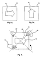
- Figures 1a, 1b and 2 A diagrammatic representation of the performance of this trick is shown in Figures 1a, 1b and 2 , reference to which is now made.
- Figures 1a and 1b show the front and back of a piece of card 10, each side displaying an arrow 12, 14, which are orientated at 90 degrees with respect to each other.
- Figure 2 shows a performer's left and right hands 16, 18 which rotate the card 10 around a diagonal axis 20.
- the arrow 14 on the reverse side which in this example is originally pointing in an upwards direction, will be rotated by 90 degrees so that when it is presented to the front, it will appear in the same orientation as the arrow 12 when said arrow 12 was originally presented to the front.
- Continued rotation of the card 10 about this axis 20 will thus result in the arrows 12, 14 consistently pointing in the same orientation when presented to the front.
- the performer typically narrates the movement of the card 10 with an amusing story, during which the performer changes the axis of rotation by moving his hands 16, 18 to rotate the card around the other diagonal axis 22. This results in the arrows 12, 14 being presented to the audience in one orientation and then another, in this case from orientated right then orientated left, then right, and so on.
- an apparatus for moving an object about separate axes of rotation comprising:
- the first driven member may be adapted to be permanently rotatably coupled to the rotary drive means.
- the first driven member may be adapted to be selectively rotatably coupled to the rotary drive means.
- the second driven member may be adapted to be permanently rotatably coupled to the rotary drive means.
- the second driven member is adapted to be selectively rotatably coupled to the rotary drive means.
- control means may be adapted to rotatably couple the first and second driven members alternately to the rotary drive means. This arrangement will accordingly result in rotation of the object about one axis of rotation at any one time.
- control means may be adapted to rotatably couple the first and second driven members to the rotary drive means simultaneously. Accordingly, this arrangement may permit simultaneous rotation of the object about the first and second axes of rotation.
- the first driven member comprises a mounting arrangement adapted to support the object. Accordingly, when the first driven member is rotatably coupled to the drive means, and the drive means is activated, the mounting arrangement will be caused to rotate about the first axis of rotation, thus resulting in the object supported thereon also being rotated about said first axis of rotation.
- the rotary drive means comprises a drive shaft.
- the control means may be adapted to selectively rotatably couple the first and second driven members to the drive shaft to cause the required rotation of the object about the first and second rotational axes.
- the second driven member is carried by the first driven member, and more particularly by the mounting arrangement of the first driven member.
- the object is secured to the second driven member. Accordingly, in this arrangement the object is mounted on the mounting arrangement of the first driven member via the second driven member.
- At least one of the first and second driven members may be hollow. This may, for example, permit electrical cabling, fibre optic cabling or the like to be passed therethrough. This may permit the object to be illuminated or alternatively permit transmission of power or electrical signals through the member.
- the object may comprise translucent and/or opaque regions. Accordingly, the object may selectively project a display onto or through the object, for example but not exclusively to provide a backlit display or to project onto a wall, ceiling or the like.
- the second driven member comprises a secondary drive shaft.
- the secondary drive shaft is secured to the object such that rotation of the secondary drive shaft causes corresponding rotation of the object.
- the secondary drive shaft is adapted to be rotatably coupled to the rotary drive means via a rotary transmission means.
- the rotary transmission means comprises a gear train.
- the rotary transmission means may comprise a rack and pinion gear mechanism, belt or chain drive mechanism or the like.
- control means may comprise a lever mechanism or the like, advantageously mounted on the first driven member.
- said lever mechanism may be adapted to securely engage the rotary drive means when rotation of the object is required about the first axis of rotation.
- the lever mechanism may be adapted to disengage the rotary drive means when rotation of the object is required about the second axis of rotation.
- the lever mechanism may be adapted to disengage the rotary drive means and engage a fixed structure to secure the first driven member against rotation, such that rotation of the rotary drive means is advantageously transmitted to rotation of the second driven member carried on the first driven member.
- the fixed structure may be a housing of the apparatus, such as a casing or frame or the like.
- the lever mechanism may be actuated by an electromagnet switching arrangement or the like.
- control means may comprise locking means to selectively secure the second driven member to the rotary drive means.
- the locking means may be adapted to selectively secure the second driven member to the rotary drive means via the mounting arrangement of the first driven member.
- the locking means may be adapted to engage the mounting arrangement to permit rotation of the object about the first axis of rotation when the first driven member is rotated.
- the control means may further comprise torque storage means, such as a torsion spring.
- torque storage means such as a torsion spring.
- the torque storage means is adapted to be secured between the rotary transmission means and the second driven member. Accordingly, in this arrangement, when the locking means is engaged, the second driven member will be rotationally constrained relative to the first driven member.
- rotation of the first driven member transmits rotation to the torque storage means via the rotary transmission means.
- rotation of the torque storage means permits rotational potential energy to be stored in the storage means.
- the locking means may be disengaged. Accordingly, the torque stored in the torque storage means may be released to rotate the second driven member to rotate the object about the second axis of rotation.
- control means may be adapted to rotatably couple the rotary drive means to the first driven member for a duration sufficient to permit a predefined angle of rotation of the object about the first axis to be achieved.
- control means may also be adapted to rotatably couple the rotary drive means to the second driven member for a duration sufficient to permit a predefined angle of rotation of the object about the second axis to be achieved.
- control means is adapted to rotatably couple the rotary drive means to the first and second driven members alternately at a frequency selected to permit intermittent rotation of the object about the first and second axes by predetermined angles of rotation. Accordingly, the control means when operating in this manner will permit the object to be rotated by a predetermined angle of rotation about the first axis, and then subsequently permit the object to be rotated by a predetermined angle of rotation about the second axis.
- control means is adapted to be operated automatically.
- control means may be adapted to be manually operated, for example by an user.
- the apparatus further comprises a motor coupled to the rotary drive means to cause rotation thereof.
- the apparatus comprises variable speed control means adapted to selectively vary the angular velocity of the rotary drive means.
- the variable speed control means may be adapted to vary the angular velocity of the rotary drive means in accordance with, for example, the selection of which of the first and second driven members is rotatably coupled thereto.
- the variable speed control means is adapted to decrease the angular velocity of the rotary drive means when rotatably coupled to the first driven member, and to increase the angular velocity of the rotary drive means when rotatably coupled to the second driven member. Accordingly, in this particular arrangement, the object will be rotated about the second axis of rotation at a greater angular velocity than about the first axis of rotation.
- the variable speed control means may alternatively be adapted to cause the object to rotate faster about the first axis of rotation than the second axis of rotation.
- variable speed control means may be adapted to cause the driven members to be rotated in one direction of rotation about the first and second axes.
- the variable speed control means is adapted to cause the first driven member to rotate in reverse directions of rotation about the first axis of rotation. Accordingly, the object may be moved to both oscillate and rotate about the first axis of rotation.
- the variable speed control means may be adapted to cause the second driven member to rotate in reverse directions of rotation about the second axis of rotation.
- variable speed control means may comprise a variable speed motor.
- Electronic control circuitry may be provided to control the variation of the speed of the motor.
- the electronic control circuitry may be programmable so as to enable the circuitry to be programmed to vary the speed of the motor in the required manner or sequence.
- such electronic control circuitry for example a programmable logic controller or the like, may be adapted to operate the control means in the required manner.
- variable speed control means comprises a mechanical assembly interposed between a drive motor and the rotary drive means.
- the mechanical assembly may be a reverted epicyclic gear train, for example.
- the epicyclic gear train comprises a first frame and a second frame pivotally mounted to the first frame.
- the first frame supports the rotary drive means.
- the second frame support is pivotally mounted about the same axis of rotation of the rotary drive means.
- the epicyclic gear train further comprises a first drive shaft mounted on the first frame, said first drive shaft adapted to drive a second drive shaft mounted on the second frame.
- the first drive shaft is adapted to drive the second drive shaft via an inter-engaging gear arrangement.
- the first drive shaft is adapted to drive the second drive shaft via an intermediate gear wheel freely rotatably mounted on the rotary drive means.
- the second drive shaft is adapted to drive the rotary drive means via an inter-engaging gear arrangement.
- the second frame may comprise a pinion gear wheel secured thereto and mounted about a pivot axis of the second frame, wherein the pinion gear wheel is adapted to engage a reciprocating rack.
- the rack is coupled to the first shaft via a crank pin arrangement. Accordingly, rotation of the first shaft will provide a reciprocating drive to the rack via the crank pin.
- the object is adapted to display at least a first image and a second image, wherein the orientation of said first and second images are manipulated by movement of the object about said axes of rotation.
- the control means of the present invention may be adapted to display the first and second images in a predetermined sequence of orientations by selectively causing rotation of the object about the first and second axes of rotation.
- the object may be adapted to be rotated about a third axis of rotation.
- the third axis of rotation is perpendicular to the first and second axes.
- the third axis projects in the z-direction.
- rotation of the object about the third axis may be achieved by rotation of the mounting arrangement of the first driven member about the third axis.
- the mounting arrangement may be adapted to be rotated by a rack and pinion gear mechanism.
- the rack and pinion gear mechanism may be curved to maintain the radial distance between the pinion and the object.
- the object may be rotated or oscillated about the centre of the object such that a viewer would be unaware of the change in orientation.
- rotation or oscillation of the object about the third axis and rotation of the object about the second axis is simultaneous.
- the rotation about the third axis of rotation advantageously disguises rotation of the object about the second axis such that a viewer is unaware of the change in orientation.
- the housing of the apparatus may be configured to disguise the change in direction.
- the viewer may be permitted to see the rotation of the object about the third axis of rotation and will be interested by the moving display that is observed.
- the apparatus of the present invention is adapted for use in a plaything which comprises an object adapted to display at least a first image and a second image, wherein the orientation of said first and second images are manipulated by movement of the object about said axes of rotation.
- the apparatus may be adapted to display all orientations of the images, for example but not exclusively arrows, in the same direction. Accordingly, the viewer or audience located at one viewing angle is shown all orientations of the images in order to observe the apparent visual illusion.
- the object may comprise a piece of card or other substantially planar body.
- the object may comprise a spherical or cube type body or the like.
- a plaything comprising:
- FIG. 3 of the drawings a first portion of an apparatus 30 for use in a plaything.
- the apparatus 30 comprises a fixed main frame 32 defining a platform 34 and an aperture 36 therein, through which aperture 36 a spherical body 38 protrudes.
- the spherical body 38 includes two arrows 40, 42 displayed on diametrically opposed surface portions of the body 38. In the embodiment shown the arrows 40, 42 are orientated at 90 degrees with respect to each other.
- the apparatus 30 of the present invention is adapted to rotate the spherical body 38 alternately about axes 44, 46 which are disposed at 45 degrees relative to each other.
- the desired effect is such that rotation of the spherical body 38 about vertical axis 44 will maintain the arrows 40, 42 in the orientations shown, and rotation of the body 38 about the inclined axis 46 will cause the arrows 40, 42 to change orientation.
- rotation of the body about axis 46 by 180 degrees will result in the arrows 40, 42 pointing in opposite directions.
- the spherical body 38 is adapted to be rotated or oscillated about vertical axis 44, giving an audience sufficient time to view the orientation and movement of the arrows 40, 42.
- the speed of rotation is increased to a level which would be difficult to detect with the eye, creating the illusion of an instantaneous direction change of the arrows 40, 42.
- the body 38 may then once again be slowly oscillated about the vertical axis 44, presenting the new orientation of arrows 40, 42 to the audience.
- the use of a spherical body 30 assists in providing the desired effect as this disguises the change in the axis of rotation.
- mirrors may be incorporated to further intrigue and entertain the audience.
- a rotating frame 48 and a drive shaft 50 Positioned below the platform 34 is a rotating frame 48 and a drive shaft 50 which extends into the rotating frame 48 and is aligned with the vertical axis 44.
- the drive shaft is rotatably supported by bearings 52, 54 which are mounted on the main frame 32.
- the rotating frame 48 includes a rotating shaft 56 rotatably mounted on the fame 48, wherein the spherical body 38 is mounted on said shaft 56. Accordingly, the arrangement is such that rotation of the rotating frame 48 results in rotation of the spherical body 38 about the vertical axis 44, and rotation of the rotating shaft 56 results in rotation of the body 38 about the inclined axis 46.
- the drive shaft 50 includes a gear wheel 58 secured thereto, and the rotating shaft 56 includes a gear wheel 60 secured thereto, wherein the gear wheels 58, 60 are rotatably engaged via an intermediate idle gear wheel 62 mounted on a shaft 64 secured to the frame 48.
- a lever 66 is pivotally mounted on the rotating frame at pivot point 68 and is caused to pivot about point 68 by an electromagnet device 70, such as a solenoid, reciprocating an operating arm 72.
- the lever 66 is adapted to be pivoted between two positions: a first position in which the lever 66 is engaged with gear wheel 58, and thus drive shaft 50, via a clutch plate 74; and a second position in which the lever 66 is disengaged from the gear wheel 58 and engaged with the main frame 32. Accordingly, when in the first position the lever 66 causes the rotating frame 48 to become rotatably coupled to the drive shaft 50, such that rotation of the drive shaft 50 causes rotation of the frame 48 and thus body 38 about axis 44.
- the lever 66 As the lever 66 is engaged with the gear wheel 58 in this first position then no rotary transmission to the rotating shaft 56 is permitted.
- the lever 66 When in the second position the lever 66 causes the rotating frame 48 to become fixed to the main frame 32, preventing frame 48 from rotating, which in turn permits gear wheel 58 to drive gear wheel 62, which in turn drives gear wheel 60 to effect rotation of the spherical body 38 about axis 46.
- the electromagnet device 70 is controlled by a controller 76 in order to alternate rotation of the body 38 about each axis 44, 46 in the desired manner.
- the lever 66 is biased towards the first position by way of an over-centre spring 78.
- the drive shaft 50 is caused to be rotated by a motor (not shown) via a variable speed mechanism, shown in Figures 4 and 5 .
- the variable speed mechanism is adapted to cause the drive shaft 50 to rotate at a lower rate when the body 38 is to be rotated about the vertical axis 44, and at an increased rate when the body 38 is to be rotated about the inclined axis 46.
- the variable speed mechanism is adapted to cause the body 38 to be oscillated about the vertical axis 44, i.e., cause reverse rotation.
- the variable speed mechanism will now be described with reference to Figures 4 and 5 .
- the variable speed mechanism incorporates a reverted epicyclic wheel train, described below.
- the mechanism includes a fixed frame 82 and a pivoting or epicyclic frame or arm 84 pivotally mounted to the first frame 82.
- the drive shaft 50 extends through both the epicyclic arm 84 and the fixed frame and provides the pivot connection therebetween.
- Mounted on the fixed frame is a rotating crank shaft 86, and mounted on the epicyclic arm is a shaft 88.
- the drive shaft 50, crank shaft 86 and shaft 88 carry a number of gear wheels which are adapted to transmit and vary rotary motion from a motor (not shown) to the drive shaft 50.
- a motor drives gear wheel 90 which is rigidly mounted on the crank shaft 86, which shaft 86 is accordingly rotated.
- Gear wheel 90 engages and drives gear wheel 92 which is freely mounted on the drive shaft 50.
- gear wheel 94 which engages and drives gear wheel 96.
- Gear wheel 96 may be rigidly secured to shaft 88 which will thus also rotate, or alternatively may be freely mounted on the shaft 88.
- Gear wheel 98 is rotatably fixed to gear wheel 96 and is therefore rotated therewith.
- Gear wheel 98 engages and rotates gear wheel 100 which is rigidly fixed to the drive shaft 50, causing said shaft 50 to be rotated.
- the specific gear ratio across the resulting gear train of the mechanism 80 may be selected in accordance with the required output speed of the drive shaft 50.
- the crank shaft 86 is adapted to be rotated at twice the average speed of the drive shaft 50.
- a pinion gear wheel 102 is secured to the epicyclic arm 84 and is mounted about drive shaft 50, wherein the pinion gear wheel 102 is adapted to engage a reciprocating rack 104.
- the epicyclic arm 84 is shown in its central position.
- the rack 104 is coupled to the crank shaft 86 via a crank pin 106 which engages a slot 108 defined in an end portion of the rack 104. Accordingly, rotation of the crank shaft 86 will provide a reciprocating drive to the rack 104 via the crank pin 106 and slot 108. In this way, one full rotation of the crank shaft 86 will cause the epicyclic arm 84 to be pivoted side-to-side once.
- the rate of pivot of the shaft will be greater that the rate of rotation of gear wheel 98.
- the lever 66 ( Figure 3 ) is advantageously positioned by the electromagnet device 70 and controller 76 ( Figure 3 ) to cause the rotating frame 48 ( Figure 3 ) to rotate, resulting in the body 38 being rotated, or indeed oscillated due to the reverse rotation of the drive shaft 50, about the vertical axis 44.
- the epicyclic arm 84 will be caused to pivot in a second, opposite direction, causing gear wheel 98 to 'walk' around gear wheel 100 in a reverse direction, resulting in an increase in the speed of the drive shaft 50.
- the lever 66 ( Figure 3 ) is advantageously positioned by the electromagnet device 70 and controller 76 ( Figure 3 ) to secure the rotating frame 48 and cause the shaft 56 ( Figure 3 ) to rotate, resulting in the body 38 being rotated at the increased rate, about the inclined axis 46.
- FIG. 6 An alternative embodiment of the present invention is shown in Figure 6 in which like components are indicated by like numerals incremented by 100.
- a frame 148 is coupled to and rotates with a first drive shaft 150, the shaft 150 orientated on a vertical axis 144.
- a second driven shaft 156 orientated on a second axis 146, is supported by bearings 102, 104, mounted in the frame 148.
- the second shaft 156 supports a spherical body 138, the second shaft 156 comprising a disc or arm 106 which permits the frame 148 to be locked to the second driven shaft 156 for approximately one full rotation of the shaft 150. This may be achieved via a solenoid arrangement or alternatively by an electromagnet selectively engaged at the appropriate time to lock the frame 148 to the second driven shaft 156.
- a wheel or gear 158 fixed to main frame 132 and being coaxial with the first driven shaft 150 engages and rotates a second wheel or gear 160 freely rotatably mounted on the second driven shaft 156 around the wheel or gear 158.
- a torsion spring 109 is mounted on the second shaft 156 and is located within a barrel or drum 110 fixedly amounted to the second gear 160.
- a support arm 112 is fixed to the second shaft 156 to assist in balance and support of the second gear 160 on the shaft 156.
- the spring 109 is fixed at one end to the second gear 160 via the barrel 110 and at the other end to the second shaft 156 via the arm 112.
- the arm 112 provides a fixing point such that rotation of the second gear 160 relative to the shaft 156 rotates or winds the spring to permit torque energy to be stored as potential energy. More than one spring 109 may be provided to improve the balance of the second shaft 156 and second driven gear 160.
- the first shaft 150 rotates through one revolution, causing the fixed gear 158 to rotate the larger gear 160.
- rotation of the first drive shaft 150 does not cause direct rotation of the body 138 via the second gear 160.
- the body 138 is thus rotated one revolution about the first axis 144.
- the second gear 160 is twice the diameter of the smaller fixed gear 158 and rotates 180 degrees about axis 146 for one rotation of shaft 150. Rotation of the second gear 160 builds a torque in the form of a rotational returning force, in the spring 109.
- This stored torque is equivalent to 180 degrees of rotation of the shaft 156 and is release once per revolution of the shaft 150 about the first axis 144 when the disc 106 engages a trigger or switch (not shown).
- the disc 106 On engaging the trigger, the disc 106 disengages the shaft 156 from the frame 148 permitting the shaft 156 to rotate the spherical body 138 about the second axis 146.
- Rotation of the shaft 156 is driven by the release of stored torque energy in the spring 109. The result is 180 degree rotation of the second shaft 156 about the second axis 146.
- the spherical body 138 includes two arrows 140, 142 displayed on diametrically opposed surface portions of the body 138, the arrow 140 pointing in a downwards direction and the second arrow 142 pointing to the right, the movement of the spherical body 138 results in a sequence of arrows 140, 142 down-right-up-left.
- a spherical body 238 may be configured to rotate or oscillate about an additional third axis 214 in order to disguise rotation of the body 238 about the second axis 244.
- the body 238 may be rotated about a first axis 244 and periodically about a second axis 246, this axis 246 being at approximately 45 degrees to the first axis 244.
- the body 238 is rotated about the second axis 246 through 180 degrees once in every 360 rotation about the first axis 244.
- the images 240, 242 on the body 238 are aligned with the second axis 246 and below a plane perpendicular to the second axis 246 which bisects the spherical body 238 (shown most clearly in Figure 7 ).
- the third axis 214 projects through the centre of the spherical body 238, permitting rotation of the body 238 about its centre, and is perpendicular to the plane of the first and second axes 244, 246.
- the apparatus 230 other than a main frame 232 may thus be rotated or oscillated about the third axis 214 from a first position as shown in Figure 7 to a second position as shown in Figure 8 .
- Rotation about the third axis 214 of rotation occurs during rotation about the second axis 246 such that images 240, 242 displayed on the spherical body 238 are hidden from a viewer, particularly if the viewer is arranged to observe the apparatus 230 from the right (as shown in the figures).
- the speed of rotation means that the change of orientation is unlikely to be detected by the viewer.
- the shift in orientation of the spherical body 238 about the second axis 246 results in a different sequence of diagrams or arrows 240, 242 being displayed to intrigue and amuse the viewer.
- the rotational speed of the spherical body 238 is less critical as the images 240, 242 are essentially hidden from the viewer when the change of orientation occurs.
- the frame 248 is rotated or oscillated about the third axis of rotation 214 by a rack and pinion gear mechanism (not shown).
- the rack is fixed to the frame 232 and the pinion gear is coupled to the rotating frame 248.
- the rack may be curved to enable the pinion to follow the desired arc about the centre of the body 238.
- the pinion gear comprises a pin (not shown), the pin engaging a slot or hole in the rotating frame 248.
- Rotation of the pinion gear causes the pinion gear to 'walk' around the rack, the pin engages with the slot or hole to drive the rotating frame from the first position to the desired second position.
- the pinion gear may be driven by any means, for example and in a preferred embodiment by a motor (not shown). It will be understood that any means for rotating the apparatus about the third axis 214 may be utilised to rotate the apparatus, other than the main frame 232. Alternatively, the pinion gear may be fixed and the rack, being fixed to the rotating frame 248, moves in relation to the pinion to drive the frame 248 through the desired arc.
- a gear ratio preferably a step-up gear ratio
- gear wheels 58, 60 and 62 mounted on the rotating frame 48 in order to provide a speed increase between the drive shaft 50 and the rotating shaft 56.
- the effect of the mechanical variable speed mechanism 80 may be achieved by electronic control means such as a programmable chip or the like, adapted to directly vary the speed of an electric motor or the like.
- the lever 66 may be adapted to be operated manually to give a user control over which axis the spherical body may be rotated or oscillated.
- the lever 66 may be adapted to be operated manually to give a user control over which axis the spherical body may be rotated or oscillated, wherein control is achieved through remote control means. Additionally, any suitable symbol or sign or the like may be displayed on the spherical body 38.
Landscapes
- Toys (AREA)
- Vehicle Body Suspensions (AREA)
- Forklifts And Lifting Vehicles (AREA)
- Portable Nailing Machines And Staplers (AREA)
Claims (53)
- Vorrichtung (30; 130; 230) zum Bewegen eines Gegenstandes (38; 138; 238) um gesonderte Rotationsachsen (44, 46; 144, 146; 244, 246, 214), wobei die Vorrichtung (30; 130; 230) Folgendes umfasst:rotierende Antriebsmittel (50; 150; 250),ein erstes angetriebenes Element (48; 148), das dafür eingerichtet ist, drehbar an die rotierenden Antriebsmittel (50; 150; 250) gekoppelt zu werden, um einen Gegenstand (38, 138, 238) um eine erste Rotationsachse (44; 144; 244) zu drehen,ein zweites angetriebenes Element (56; 156; 256), das dafür eingerichtet ist, drehbar an die gleiche rotierenden Antriebsmittel (50; 150; 250) gekoppelt zu werden, um den Gegenstand (38; 138; 238) um eine zweite, abweichende, Rotationsachse (46; 146; 246) zu drehen, undSteuerungsmittel (66), die dafür eingerichtet sind, wenigstens eines von dem ersten (48; 148) und dem zweiten (56, 156; 256) angetriebenen Element drehbar an die rotierenden Antriebsmittel (50; 150; 250) zu koppeln.
- Vorrichtung (30; 130; 230) nach Anspruch 1 wobei das erste angetriebene Element (48; 148) dafür eingerichtet ist, selektiv drehbar an die rotierenden Antriebsmittel (50; 150; 250) gekoppelt zu werden.
- Vorrichtung (30; 130; 230) nach Anspruch 1 oder 2, wobei das zweite angetriebene Element (56; 156; 256) dafür eingerichtet ist, selektiv drehbar an die rotierenden Antriebsmittel (50; 150; 250) gekoppelt zu werden.
- Vorrichtung (30; 130; 230) nach Anspruch 1, 2 oder 3, wobei das Steuerungsmittel (66) dafür eingerichtet ist, das erste (48; 148) und das zweite (56, 156; 256) angetriebene Element abwechselnd drehbar an die rotierenden Antriebsmittel (50; 150; 250) zu koppeln.
- Vorrichtung (30; 130; 230) nach Anspruch 1, 2 oder 3, wobei das Steuerungsmittel (66) dafür eingerichtet ist, das erste (48; 148) und das zweite (56, 156; 256) angetriebene Element gleichzeitig drehbar an die rotierenden Antriebsmittel (50; 150; 250) zu koppeln.
- Vorrichtung (30; 130; 230) nach einem der vorhergehenden Ansprüche, wobei das erste angetriebene Element (48; 148) eine Anbringungsanordnung umfasst, die dafür eingerichtet ist, den Gegenstand (38, 138, 238) zu tragen.
- Vorrichtung (30; 130; 230) nach einem der vorhergehenden Ansprüche, wobei das rotierende Antriebsmittel (50; 150; 250) eine einzige Antriebswelle (50; 150; 250) umfasst.
- Vorrichtung (30; 130; 230) nach Anspruch 7, wobei das Steuerungsmittel (66) dafür eingerichtet ist, selektiv das erste (48; 148) und das zweite (56, 156; 256) angetriebene Element drehbar an die Antriebswelle (50; 150; 250) zu koppeln.
- Vorrichtung (30; 130; 230) nach einem der vorhergehenden Ansprüche, wobei das zweite angetriebene Element (56; 156; 256) durch das erste angetriebene Element (48; 148) getragen wird.
- Vorrichtung (30; 130; 230) nach einem der vorhergehenden Ansprüche, wobei der Gegenstand (38; 138; 238) an dem zweiten angetriebenen Element (56; 156; 256) befestigt ist.
- Vorrichtung (30; 130; 230) nach einem der vorhergehenden Ansprüche, wobei wenigstens eines von dem ersten (48; 148) und dem zweiten (56, 156; 256) angetriebenen Element hohl sein kann.
- Vorrichtung (30; 130; 230) nach einem der vorhergehenden Ansprüche, wobei das zweite angetriebene Element (56; 156; 256) eine sekundäre Antriebswelle (56; 156; 256) umfasst.
- Vorrichtung (30; 130; 230) nach Anspruch 12, wobei die sekundäre Antriebswelle (56; 156; 256) derart an dem Gegenstand (38; 138; 238) befestigt ist, dass eine Drehung der sekundären Antriebswelle (56; 156; 256) eine entsprechende Drehung des Gegenstandes (38; 138; 238) bewirkt.
- Vorrichtung (30; 130; 230) nach Anspruch 12 oder 13, wobei die sekundäre Antriebswelle (56; 156; 256) dafür eingerichtet ist, über ein drehbares Übertragungsmittel (58, 60, 62) an das rotierende Antriebsmittel (50; 150; 250) gekoppelt zu werden.
- Vorrichtung (30; 130; 230) nach Anspruch 14, wobei das drehbare Übertragungsmittel (58, 60, 62) einen Getriebezug (58, 60, 62) umfasst.
- Vorrichtung (30; 130; 230) nach Anspruch 14, wobei das drehbare Übertragungsmittel (58, 60, 62) einen Zahnstangen-Getriebemechanismus umfasst.
- Vorrichtung (30; 130; 230) nach einem der vorhergehenden Ansprüche, wobei das Steuerungsmittel (66) einen Hebelmechanismus (66) umfasst, der an dem ersten angetriebenen Element (48; 148) angebracht ist.
- Vorrichtung (30; 130; 230) nach Anspruch 17, wobei der Hebelmechanismus (66) dafür eingerichtet ist, die rotierenden Antriebsmittel (50; 150; 250) sicher in Eingriff zu nehmen, wenn eine Drehung des Gegenstandes (38; 138; 238) um die erste Rotationsachse (44; 144; 244) erforderlich ist, und die rotierenden Antriebsmittel (50; 150; 250) auszurücken, wenn eine Drehung des Gegenstandes (38; 138; 238) um die zweite Rotationsachse (46; 146; 246) erforderlich ist.
- Vorrichtung (30; 130; 230) nach Anspruch 18, wobei, wenn es erforderlich ist, dass der Gegenstand (38; 138; 238) um die zweite Rotationsachse (46; 146; 246) gedreht wird, der Hebelmechanismus (66) dafür eingerichtet ist, die rotierenden Antriebsmittel (50; 150; 250) auszurücken und eine feststehende Struktur (32; 132; 232) in Eingriff zu nehmen, um das erste angetriebene Element 48;148) gegen eine Drehung zu sichern,
- Vorrichtung (30; 130; 230) nach einem der Ansprüche 1 bis 16, wobei das Steuerungsmittel (66) Verriegelungsmittel (74) umfasst, um das zweite angetriebene Element (56; 156; 256) selektiv an den rotierenden Antriebsmitteln (50; 150; 250) zu befestigen.
- Vorrichtung (30; 130; 230) nach Anspruch 20, wobei das Verriegelungsmittel (74) dafür eingerichtet ist, das zweite angetriebene Element (56; 156; 256) über die Anbringungsanordnung (48; 148) des ersten angetriebenen Elements (48; 148) selektiv an den rotierenden Antriebsmitteln (50; 150; 250) zu befestigen.
- Vorrichtung (30; 130; 230) nach einem der vorhergehenden Ansprüche, wobei das Steuerungsmittel (66) Drehmometrtspeichermittel (109) umfasst.
- Vorrichtung (30; 130; 230) nach Anspruch 22, wobei das Drehmomentspeichermittel (109) dafür eingerichtet ist, zwischen den rotierenden Übertragungsmitteln (58, 60, 62) und dem zweiten angetriebenen Element (56; 156; 256) befestigt zu sein, und bei Anwendung eine Drehung des ersten angetriebenen Elements (48; 148) die Drehung über die rotierenden Übertragungsmittel (58, 60, 62) zu dem Drehmomentspeichermittel (109) überträgt und eine Drehung des Drehmomentspeichermittels (109) ermöglicht, dass potentielle Rotationsenergie in dem Drehmomentspeichermittel (109) gespeichert wird.
- Vorrichtung (30; 130; 230) nach Anspruch 23, soweit abhängig von einem der Ansprüche 20 bis 22, wobei, wenn es bei Anwendung erforderlich ist, dass der Gegenstand (38; 138; 238) durch das zweite angetriebene Element (56; 156; 256) gedreht wird, das Verriegelungsmittel (74) ausgerückt wird derart, dass das in dem Drehmomentspeichermittel (109) gespeicherte Drehmoment freigesetzt wird, um das zweite angetriebene Element (56; 156; 256) zu drehen.
- Vorrichtung (30; 130; 230) nach einem der vorhergehenden Ansprüche, wobei das Steuerungsmittel (66) dafür eingerichtet ist, die rotierenden Antriebsmittel (50; 150; 250) für eine Dauer an das erste angetriebene Element (48; 148) zu koppeln, die dazu ausreicht, zu ermöglichen, dass ein vordefinierter Rotationswinkel des Gegenstandes (38; 138; 238) um die erste Achse (44; 144; 244) erreicht wird.
- Vorrichtung (30; 130; 230) nach einem der vorhergehenden Ansprüche, wobei das Steuerungsmittel (66) dafür eingerichtet ist, die rotierenden Antriebsmittel (50; 150; 250) für eine Dauer an das zweite angetriebene Element (56; 156; 256) zu koppeln, die dazu ausreicht, zu ermöglichen, dass ein vordefinierter Rotationswinkel des Gegenstandes (38; 138; 238) um die zweite Achse (46; 146; 246) erreicht wird.
- Vorrichtung (30; 130; 230) nach einem der vorhergehenden Ansprüche, wobei das Steuerungsmittel (66) dafür eingerichtet ist, die rotierenden Antriebsmittel (50; 150; 250) abwechselnd mit einer Frequenz an das erste (48; 148) und das zweite (56; 156; 256) angetriebene Element zu koppeln, die dafür ausgewählt ist, eine intermittierende Drehung des Gegenstandes (38; 138; 238) um die erste (44; 144; 244) und die zweite (46; 146; 246) Achse um vorbestimmte Rotationswinkel zu ermöglichen.
- Vorrichtung (30; 130; 230) nach einem der vorhergehenden Ansprüche, die ferner einen Motor umfasst, der an die rotierenden Antriebsmittel (50; 150; 250) gekoppelt ist, um eine Drehung derselben zu bewirken.
- Vorrichtung (30; 130; 230) nach einem der vorhergehenden Ansprüche, die ferner regelbare Drehzahlsteuerungsmittel (80) umfasst, die dafür eingerichtet sind, selektiv die Winkelgeschwindigkeit der rotierenden Antriebsmittel (50; 150; 250) zu verändern.
- Vorrichtung (30; 130; 230) nach Anspruch 29, wobei das regelbare Drehzahlsteuerungsmittel (80) dafür eingerichtet ist, die Winkelgeschwindigkeit der rotierenden Antriebsmittel (50; 150; 250) in Übereinstimmung mit der Auswahl zu verändern, welches von dem ersten (48; 148) und dem zweiten (56; 156; 256) angetriebenen Element drehbar an dieselben gekoppelt ist.
- Vorrichtung (30; 130; 230) nach Anspruch 29 oder 30, wobei das regelbare Drehzahlsteuerungsmittel (80) dafür eingerichtet ist, die Winkelgeschwindigkeit der rotierenden Antriebsmittel (50; 150; 250) zu verringern, wenn sie drehbar an das erste angetriebene Element (48; 148) gekoppelt sind, und die Winkelgeschwindigkeit der rotierenden Antriebsmittel (50; 150; 250) zu steigern, wenn sie drehbar an das zweite angetriebene Element (56; 156; 256) gekoppelt sind.
- Vorrichtung (30; 130; 230) nach Anspruch 29, 30 oder 31, wobei das regelbare Drehzahlsteuerungsmittel (80) dafür eingerichtet ist, zu bewirken, dass die angetriebenen Elemente (48, 56; 148, 156; 256) in einer Rotationsrichtung um die erste (44; 144; 244) und die zweite (46; 146; 246) Achse gedreht wenden.
- Vorrichtung (30; 130; 230) nach Anspruch 29, 30 oder 31, wobei das regelbare Drehzahlsteuerungsmittel (80) dafür eingerichtet ist, zu bewirken, dass sich das erste angetriebene Element (48; 148) in entgegengesetzten Rotationsrichtungen um die erste Rotationsachse (44; 144; 244) dreht.
- Vorrichtung (30; 130; 230) nach einem der Ansprüche 29 bis 33, wobei das regelbare Drehzahlsteuerungsmittel (80) einen Motor mit regelbarer Drehzahl umfassen kann.
- Vorrichtung (30; 130; 230) nach einem der Ansprüche 29 bis 33, wobei das verstellbare Drehzahlsteuerungsmittel (80) eine mechanische Baugruppe umfasst, die zwischen einen Antriebsmotor und die rotierenden Antriebsmittel (50; 150; 250) geschaltet ist.
- Vorrichtung (30; 130; 230) nach Anspruch 35, wobei die mechanische Baugruppe ein umgekehrtes Umlaufgetriebe ist.
- Vorrichtung (30; 130; 230) nach Anspruch 35 oder 36, wobei die mechanische Baugruppe einen ersten Rahmen (82) und einen zweiten Rahmen (84), der schwenkbar an dem ersten Rahmen (82) angebracht ist, umfasst.
- Vorrichtung (30; 130; 230) nach Anspruch 37, wobei der erste Rahmen (82) die rotierenden Antriebsmittel (50; 150; 250) trägt.
- Vorrichtung (30; 130; 230) nach Anspruch 37 oder 38, wobei die zweite Rahmenstütze schwenkbar um die gleiche Rotationsachse wie die rotierenden Antriebsmittel (50; 150; 250) angebracht ist.
- Vorrichtung (30; 130; 230) nach Anspruch 37, 38 oder 39, wobei die mechanische Baugruppe ferner eine erste Antriebswelle (86) umfasst, die an dem ersten Rahmen (82) angebracht ist, wobei die erste Antriebswelle (86) dafür eingerichtet ist, eine zweite Antriebswelle (88) anzutreiben, die an dem zweiten Rahmen (84) angebracht ist.
- Vorrichtung (30; 130; 230) nach Anspruch 40, wobei die erste Antriebswelle (86) dafür eingerichtet ist, die zweite Antriebswelle (88) über eine wechselseitig eingreifende Getriebeanordnung (90, 92, 94, 96) anzutreiben.
- Vorrichtung (30; 130; 230) nach Anspruch 41, wobei die erste Antriebswelle (86) dafür eingerichtet ist, die zweite Antribswelle (88) über ein Zwischengetrieberad (92) anzutreiben, das frei drehbar an den rotierenden Antriebsmitteln (50; 150; 250) angebracht ist.
- Vorrichtung (30; 130; 230) nach Anspruch 40, 41 oder 42, wobei die zweite Antriebswelle (88) dafür eingerichtet ist, die rotierenden Antriebsmittel (50; 150; 250) über eine wechselseitig eingreifende Getriebeanordnung (98, 100) anzutreiben.
- Vorrichtung (30; 130; 230) nach einem der Ansprüche 37 bis 43, wobei der zweite Rahmen (84) ein Ritzelrad (102) umfasst, das an demselben befestigt und um eine Schwenkachse des zweiten Rahmens (84) angebracht ist, wobei das Ritzelrad (102) dafür eingerichtet ist, eine hin- und hergehende Zahnstange (104) in Eingriff zu nehmen.
- Vorrichtung (30; 130; 230) nach Anspruch 44, wobei die Zahnstange (104) über eine Kurbelzapfenanordnung (106) an die erste Welle (86) gekoppelt ist.
- Vorrichtung (30; 130; 230) nach einem der vorhergehenden Ansprüche, wobei der Gegenstand (38; 138; 238) dafür eingerichtet ist, wenigstens ein erstes Bild (40) und ein zweites Bild (42) anzuzeigen, wobei die Ausrichtung des ersten (40) und des zweiten (42) Bildes durch eine Bewegung des Gegenstandes (38; 138; 238) um die Rotationsachsen (44, 46; 144, 146; 244, 246, 214) manipuliert wird.
- Vorrichtung (30; 130; 230) nach einem der vorhergehenden Ansprüche, wobei der Gegenstand (38; 138; 238) dafür eingerichtet ist, um eine dritte Rotationsachse (214) gedreht zu werden.
- Vorrichtung (30; 130; 230) nach Anspruch 47, wobei die dritte Rotationsachse (214) senkrecht zu der ersten (44; 144; 244) und der zweiten (46; 146; 246) Achse ist.
- Vorrichtung (30; 130; 230) nach Anspruch 47 oder 48, wobei eine Drehung des Gegenstandes (38; 138; 238) um die dritte Achse (214) durch eine Drehung der Anbringungsanordnung des ersten angetriebenen Elements (48; 148) um die dritte Achse (214) erreicht wird.
- Vorrichtung (30; 130; 230) nach Anspruch 47, 48 oder 49, wobei eine Drehung des Gegenstandes (38; 138; 238) um die dritte Achse (214) und eine Drehung des Gegenstandes (38; 138; 238) um die zweite Achse (46; 146; 246) gleichzeitig erfolgen.
- Vorrichtung (30; 130; 230) nach einem der vorhergehenden Ansprüche, eingerichtet für eine Verwendung in einem Spielzeug, das einen Gegenstand (38; 138; 238) umfasst, der dafür eingerichtet ist, wenigstens ein erstes Bild (40) und ein zweites Bild (42) anzuzeigen, wobei die Ausrichtung des ersten (40) und des zweiten (42) Bildes durch eine Bewegung des Gegenstandes (38; 138; 238) um die Rotationsachsen (44, 46; 144, 146; 244, 246, 214) manipuliert wird.
- Vorrichtung (30; 130; 230) nach Anspruch 51, wobei das erste angetriebene Element (48; 148) dafür eingerichtet ist, drehbar an die rotierenden Antriebsmittel (50; 150; 250) gekoppelt zu werden, um den Gegenstand (38; 138; 238) um eine erste Rotationsachse (44; 144; 244) zu drehen, um das erste (40) und das zweite (42) Bild in einer ersten Folge zu zeigen.
- Vorrichtung (30; 130; 230) nach Anspruch 51 oder 52, das zweite angetriebenen Element (56; 156; 256) dafür eingerichtet ist, drehbar an die gleichen rotierenden Antriebsmittel (50; 150; 250) gekoppelt zu werden, um den Gegenstand (38; 138; 238) um eine zweite, abweichende Rotationsache (46; 146; 246) zu drehen, um das erste (40) und das zweite (42) Bild in einer zweiten Folge zu zeigen.
Applications Claiming Priority (1)
| Application Number | Priority Date | Filing Date | Title |
|---|---|---|---|
| GBGB0504470.6A GB0504470D0 (en) | 2005-03-04 | 2005-03-04 | Apparatus for moving an object |
Publications (2)
| Publication Number | Publication Date |
|---|---|
| EP1698385A1 EP1698385A1 (de) | 2006-09-06 |
| EP1698385B1 true EP1698385B1 (de) | 2009-12-09 |
Family
ID=34451785
Family Applications (1)
| Application Number | Title | Priority Date | Filing Date |
|---|---|---|---|
| EP06251179A Expired - Lifetime EP1698385B1 (de) | 2005-03-04 | 2006-03-06 | Vorrichtung zum Bewegen eines Gegenstands |
Country Status (4)
| Country | Link |
|---|---|
| EP (1) | EP1698385B1 (de) |
| AT (1) | ATE451158T1 (de) |
| DE (1) | DE602006010922D1 (de) |
| GB (1) | GB0504470D0 (de) |
Families Citing this family (1)
| Publication number | Priority date | Publication date | Assignee | Title |
|---|---|---|---|---|
| CN108325223B (zh) * | 2018-05-15 | 2023-10-31 | 广州童方科技有限公司 | 一种用于娱乐的玩具枪 |
Family Cites Families (5)
| Publication number | Priority date | Publication date | Assignee | Title |
|---|---|---|---|---|
| US2957252A (en) * | 1959-12-11 | 1960-10-25 | William A Pain | Globe support and orienting means |
| US3377719A (en) * | 1964-10-06 | 1968-04-16 | Roman B. Kroitor | Globe navigation simulator |
| US3571954A (en) * | 1966-05-13 | 1971-03-23 | Planetaria Inc | Space transit simulator planetarium |
| US3863363A (en) * | 1970-08-25 | 1975-02-04 | Minolta Camera Kk | Planetarium |
| US4973215A (en) * | 1986-02-18 | 1990-11-27 | Robotics Research Corporation | Industrial robot with servo |
-
2005
- 2005-03-04 GB GBGB0504470.6A patent/GB0504470D0/en not_active Ceased
-
2006
- 2006-03-06 DE DE602006010922T patent/DE602006010922D1/de not_active Expired - Fee Related
- 2006-03-06 AT AT06251179T patent/ATE451158T1/de not_active IP Right Cessation
- 2006-03-06 EP EP06251179A patent/EP1698385B1/de not_active Expired - Lifetime
Also Published As
| Publication number | Publication date |
|---|---|
| ATE451158T1 (de) | 2009-12-15 |
| GB0504470D0 (en) | 2005-04-13 |
| DE602006010922D1 (de) | 2010-01-21 |
| EP1698385A1 (de) | 2006-09-06 |
Similar Documents
| Publication | Publication Date | Title |
|---|---|---|
| JP5222193B2 (ja) | 可動役物装置 | |
| JP4667402B2 (ja) | 弾球遊技機の演出装置 | |
| JP5701580B2 (ja) | 遊技機 | |
| JP4534767B2 (ja) | 遊技機 | |
| JP2012110432A (ja) | 遊技機 | |
| JP2007268040A (ja) | 遊技機用の可動式演出装置 | |
| JP2016123800A (ja) | 遊技機 | |
| GB2268415A (en) | Machines for amusement and playing games | |
| EP0577415A2 (de) | Maschine zum Vergnügen und Spielen | |
| JP2010220868A (ja) | 可動役物装置 | |
| JP4332564B2 (ja) | 弾球遊技機の演出装置 | |
| EP1698385B1 (de) | Vorrichtung zum Bewegen eines Gegenstands | |
| US20090239443A1 (en) | System for representing an autonomous entity | |
| JP4187694B2 (ja) | 遊技機 | |
| EP1440427B1 (de) | Gerät zur erzeugung einer optischen täuschung | |
| JP5077890B2 (ja) | 遊技機 | |
| JP2012115430A (ja) | 遊技機 | |
| US8833189B2 (en) | Gyroscope device | |
| KR20030089653A (ko) | 모니터 및 텔레비전의 위치 조종 장치 | |
| JP2008229055A (ja) | 遊技演出体及び遊技機 | |
| JP2012200435A (ja) | 遊技機用光演出装置及び遊技機 | |
| JP4726921B2 (ja) | 装飾体ユニット、遊技盤、及びパチンコ遊技機 | |
| JP4667401B2 (ja) | 弾球遊技機の演出装置 | |
| JP2019069059A (ja) | 揺動器 | |
| JP6156891B2 (ja) | 遊技機 |
Legal Events
| Date | Code | Title | Description |
|---|---|---|---|
| PUAI | Public reference made under article 153(3) epc to a published international application that has entered the european phase |
Free format text: ORIGINAL CODE: 0009012 |
|
| AK | Designated contracting states |
Kind code of ref document: A1 Designated state(s): AT BE BG CH CY CZ DE DK EE ES FI FR GB GR HU IE IS IT LI LT LU LV MC NL PL PT RO SE SI SK TR |
|
| AX | Request for extension of the european patent |
Extension state: AL BA HR MK YU |
|
| 17P | Request for examination filed |
Effective date: 20070118 |
|
| 17Q | First examination report despatched |
Effective date: 20070216 |
|
| AKX | Designation fees paid |
Designated state(s): AT BE BG CH CY CZ DE DK EE ES FI FR GB GR HU IE IS IT LI LT LU LV MC NL PL PT RO SE SI SK TR |
|
| GRAP | Despatch of communication of intention to grant a patent |
Free format text: ORIGINAL CODE: EPIDOSNIGR1 |
|
| GRAS | Grant fee paid |
Free format text: ORIGINAL CODE: EPIDOSNIGR3 |
|
| GRAA | (expected) grant |
Free format text: ORIGINAL CODE: 0009210 |
|
| AK | Designated contracting states |
Kind code of ref document: B1 Designated state(s): AT BE BG CH CY CZ DE DK EE ES FI FR GB GR HU IE IS IT LI LT LU LV MC NL PL PT RO SE SI SK TR |
|
| REG | Reference to a national code |
Ref country code: GB Ref legal event code: FG4D |
|
| REG | Reference to a national code |
Ref country code: CH Ref legal event code: EP |
|
| REG | Reference to a national code |
Ref country code: IE Ref legal event code: FG4D |
|
| REF | Corresponds to: |
Ref document number: 602006010922 Country of ref document: DE Date of ref document: 20100121 Kind code of ref document: P |
|
| REG | Reference to a national code |
Ref country code: NL Ref legal event code: VDEP Effective date: 20091209 |
|
| PG25 | Lapsed in a contracting state [announced via postgrant information from national office to epo] |
Ref country code: FI Free format text: LAPSE BECAUSE OF FAILURE TO SUBMIT A TRANSLATION OF THE DESCRIPTION OR TO PAY THE FEE WITHIN THE PRESCRIBED TIME-LIMIT Effective date: 20091209 Ref country code: LT Free format text: LAPSE BECAUSE OF FAILURE TO SUBMIT A TRANSLATION OF THE DESCRIPTION OR TO PAY THE FEE WITHIN THE PRESCRIBED TIME-LIMIT Effective date: 20091209 Ref country code: SE Free format text: LAPSE BECAUSE OF FAILURE TO SUBMIT A TRANSLATION OF THE DESCRIPTION OR TO PAY THE FEE WITHIN THE PRESCRIBED TIME-LIMIT Effective date: 20091209 |
|
| LTIE | Lt: invalidation of european patent or patent extension |
Effective date: 20091209 |
|
| PG25 | Lapsed in a contracting state [announced via postgrant information from national office to epo] |
Ref country code: LV Free format text: LAPSE BECAUSE OF FAILURE TO SUBMIT A TRANSLATION OF THE DESCRIPTION OR TO PAY THE FEE WITHIN THE PRESCRIBED TIME-LIMIT Effective date: 20091209 Ref country code: SI Free format text: LAPSE BECAUSE OF FAILURE TO SUBMIT A TRANSLATION OF THE DESCRIPTION OR TO PAY THE FEE WITHIN THE PRESCRIBED TIME-LIMIT Effective date: 20091209 Ref country code: PL Free format text: LAPSE BECAUSE OF FAILURE TO SUBMIT A TRANSLATION OF THE DESCRIPTION OR TO PAY THE FEE WITHIN THE PRESCRIBED TIME-LIMIT Effective date: 20091209 |
|
| PG25 | Lapsed in a contracting state [announced via postgrant information from national office to epo] |
Ref country code: AT Free format text: LAPSE BECAUSE OF FAILURE TO SUBMIT A TRANSLATION OF THE DESCRIPTION OR TO PAY THE FEE WITHIN THE PRESCRIBED TIME-LIMIT Effective date: 20091209 |
|
| PG25 | Lapsed in a contracting state [announced via postgrant information from national office to epo] |
Ref country code: NL Free format text: LAPSE BECAUSE OF FAILURE TO SUBMIT A TRANSLATION OF THE DESCRIPTION OR TO PAY THE FEE WITHIN THE PRESCRIBED TIME-LIMIT Effective date: 20091209 Ref country code: ES Free format text: LAPSE BECAUSE OF FAILURE TO SUBMIT A TRANSLATION OF THE DESCRIPTION OR TO PAY THE FEE WITHIN THE PRESCRIBED TIME-LIMIT Effective date: 20100320 Ref country code: RO Free format text: LAPSE BECAUSE OF FAILURE TO SUBMIT A TRANSLATION OF THE DESCRIPTION OR TO PAY THE FEE WITHIN THE PRESCRIBED TIME-LIMIT Effective date: 20091209 Ref country code: PT Free format text: LAPSE BECAUSE OF FAILURE TO SUBMIT A TRANSLATION OF THE DESCRIPTION OR TO PAY THE FEE WITHIN THE PRESCRIBED TIME-LIMIT Effective date: 20100409 Ref country code: EE Free format text: LAPSE BECAUSE OF FAILURE TO SUBMIT A TRANSLATION OF THE DESCRIPTION OR TO PAY THE FEE WITHIN THE PRESCRIBED TIME-LIMIT Effective date: 20091209 Ref country code: BG Free format text: LAPSE BECAUSE OF FAILURE TO SUBMIT A TRANSLATION OF THE DESCRIPTION OR TO PAY THE FEE WITHIN THE PRESCRIBED TIME-LIMIT Effective date: 20100309 Ref country code: IS Free format text: LAPSE BECAUSE OF FAILURE TO SUBMIT A TRANSLATION OF THE DESCRIPTION OR TO PAY THE FEE WITHIN THE PRESCRIBED TIME-LIMIT Effective date: 20100409 |
|
| PG25 | Lapsed in a contracting state [announced via postgrant information from national office to epo] |
Ref country code: CZ Free format text: LAPSE BECAUSE OF FAILURE TO SUBMIT A TRANSLATION OF THE DESCRIPTION OR TO PAY THE FEE WITHIN THE PRESCRIBED TIME-LIMIT Effective date: 20091209 Ref country code: SK Free format text: LAPSE BECAUSE OF FAILURE TO SUBMIT A TRANSLATION OF THE DESCRIPTION OR TO PAY THE FEE WITHIN THE PRESCRIBED TIME-LIMIT Effective date: 20091209 Ref country code: BE Free format text: LAPSE BECAUSE OF FAILURE TO SUBMIT A TRANSLATION OF THE DESCRIPTION OR TO PAY THE FEE WITHIN THE PRESCRIBED TIME-LIMIT Effective date: 20091209 |
|
| PLBE | No opposition filed within time limit |
Free format text: ORIGINAL CODE: 0009261 |
|
| STAA | Information on the status of an ep patent application or granted ep patent |
Free format text: STATUS: NO OPPOSITION FILED WITHIN TIME LIMIT |
|
| PG25 | Lapsed in a contracting state [announced via postgrant information from national office to epo] |
Ref country code: CY Free format text: LAPSE BECAUSE OF FAILURE TO SUBMIT A TRANSLATION OF THE DESCRIPTION OR TO PAY THE FEE WITHIN THE PRESCRIBED TIME-LIMIT Effective date: 20091209 Ref country code: MC Free format text: LAPSE BECAUSE OF NON-PAYMENT OF DUE FEES Effective date: 20100331 Ref country code: GR Free format text: LAPSE BECAUSE OF FAILURE TO SUBMIT A TRANSLATION OF THE DESCRIPTION OR TO PAY THE FEE WITHIN THE PRESCRIBED TIME-LIMIT Effective date: 20100310 |
|
| REG | Reference to a national code |
Ref country code: CH Ref legal event code: PL |
|
| 26N | No opposition filed |
Effective date: 20100910 |
|
| REG | Reference to a national code |
Ref country code: FR Ref legal event code: ST Effective date: 20101130 |
|
| PG25 | Lapsed in a contracting state [announced via postgrant information from national office to epo] |
Ref country code: FR Free format text: LAPSE BECAUSE OF NON-PAYMENT OF DUE FEES Effective date: 20100331 Ref country code: DK Free format text: LAPSE BECAUSE OF FAILURE TO SUBMIT A TRANSLATION OF THE DESCRIPTION OR TO PAY THE FEE WITHIN THE PRESCRIBED TIME-LIMIT Effective date: 20091209 Ref country code: IE Free format text: LAPSE BECAUSE OF NON-PAYMENT OF DUE FEES Effective date: 20100306 |
|
| PG25 | Lapsed in a contracting state [announced via postgrant information from national office to epo] |
Ref country code: CH Free format text: LAPSE BECAUSE OF NON-PAYMENT OF DUE FEES Effective date: 20100331 Ref country code: LI Free format text: LAPSE BECAUSE OF NON-PAYMENT OF DUE FEES Effective date: 20100331 Ref country code: DE Free format text: LAPSE BECAUSE OF NON-PAYMENT OF DUE FEES Effective date: 20101001 |
|
| PG25 | Lapsed in a contracting state [announced via postgrant information from national office to epo] |
Ref country code: IT Free format text: LAPSE BECAUSE OF FAILURE TO SUBMIT A TRANSLATION OF THE DESCRIPTION OR TO PAY THE FEE WITHIN THE PRESCRIBED TIME-LIMIT Effective date: 20091209 |
|
| PGFP | Annual fee paid to national office [announced via postgrant information from national office to epo] |
Ref country code: GB Payment date: 20120301 Year of fee payment: 7 |
|
| PG25 | Lapsed in a contracting state [announced via postgrant information from national office to epo] |
Ref country code: HU Free format text: LAPSE BECAUSE OF FAILURE TO SUBMIT A TRANSLATION OF THE DESCRIPTION OR TO PAY THE FEE WITHIN THE PRESCRIBED TIME-LIMIT Effective date: 20100610 Ref country code: LU Free format text: LAPSE BECAUSE OF NON-PAYMENT OF DUE FEES Effective date: 20100306 |
|
| PG25 | Lapsed in a contracting state [announced via postgrant information from national office to epo] |
Ref country code: TR Free format text: LAPSE BECAUSE OF FAILURE TO SUBMIT A TRANSLATION OF THE DESCRIPTION OR TO PAY THE FEE WITHIN THE PRESCRIBED TIME-LIMIT Effective date: 20091209 |
|
| GBPC | Gb: european patent ceased through non-payment of renewal fee |
Effective date: 20130306 |
|
| PG25 | Lapsed in a contracting state [announced via postgrant information from national office to epo] |
Ref country code: GB Free format text: LAPSE BECAUSE OF NON-PAYMENT OF DUE FEES Effective date: 20130306 |