EP1698511A1 - Dispositif permettant de régler automatiquement le profil d'un siège, en particulier d'un siège - Google Patents
Dispositif permettant de régler automatiquement le profil d'un siège, en particulier d'un siège Download PDFInfo
- Publication number
- EP1698511A1 EP1698511A1 EP06110030A EP06110030A EP1698511A1 EP 1698511 A1 EP1698511 A1 EP 1698511A1 EP 06110030 A EP06110030 A EP 06110030A EP 06110030 A EP06110030 A EP 06110030A EP 1698511 A1 EP1698511 A1 EP 1698511A1
- Authority
- EP
- European Patent Office
- Prior art keywords
- seat
- plate
- axis
- bladder
- opposite
- Prior art date
- Legal status (The legal status is an assumption and is not a legal conclusion. Google has not performed a legal analysis and makes no representation as to the accuracy of the status listed.)
- Granted
Links
Images

Classifications
-
- A—HUMAN NECESSITIES
- A47—FURNITURE; DOMESTIC ARTICLES OR APPLIANCES; COFFEE MILLS; SPICE MILLS; SUCTION CLEANERS IN GENERAL
- A47C—CHAIRS; SOFAS; BEDS
- A47C4/00—Foldable, collapsible or dismountable chairs
- A47C4/54—Inflatable chairs
-
- B—PERFORMING OPERATIONS; TRANSPORTING
- B60—VEHICLES IN GENERAL
- B60N—SEATS SPECIALLY ADAPTED FOR VEHICLES; VEHICLE PASSENGER ACCOMMODATION NOT OTHERWISE PROVIDED FOR
- B60N2/00—Seats specially adapted for vehicles; Arrangement or mounting of seats in vehicles
- B60N2/02—Seats specially adapted for vehicles; Arrangement or mounting of seats in vehicles the seat or part thereof being movable, e.g. adjustable
- B60N2/0224—Non-manual adjustments, e.g. with electrical operation
- B60N2/0244—Non-manual adjustments, e.g. with electrical operation with logic circuits
- B60N2/026—Non-manual adjustments, e.g. with electrical operation with logic circuits varying hardness or support of upholstery, e.g. for tuning seat comfort when driving curved roads
-
- B—PERFORMING OPERATIONS; TRANSPORTING
- B60—VEHICLES IN GENERAL
- B60N—SEATS SPECIALLY ADAPTED FOR VEHICLES; VEHICLE PASSENGER ACCOMMODATION NOT OTHERWISE PROVIDED FOR
- B60N2/00—Seats specially adapted for vehicles; Arrangement or mounting of seats in vehicles
- B60N2/90—Details or parts not otherwise provided for
- B60N2/914—Hydro-pneumatic adjustments of the shape
-
- B—PERFORMING OPERATIONS; TRANSPORTING
- B60—VEHICLES IN GENERAL
- B60N—SEATS SPECIALLY ADAPTED FOR VEHICLES; VEHICLE PASSENGER ACCOMMODATION NOT OTHERWISE PROVIDED FOR
- B60N2/00—Seats specially adapted for vehicles; Arrangement or mounting of seats in vehicles
- B60N2/90—Details or parts not otherwise provided for
- B60N2/986—Side-rests
- B60N2/99—Side-rests adjustable
Definitions
- the invention relates to a system for automatic adjustment of the contour, especially for adjusting the lateral support of a seat, in particular vehicle seat for automobiles, aircraft od.
- a substantially rigid plate pivotable about an axis and thus hinged on the opposite side with the seat frame or the seat pan is connected, wherein between the plate and the seat frame or the seat pan at least one fluidbehellbare and thus volume changeable bubble is attached, and a seat, especially vehicle seat for automobiles, aircraft od.
- a seat and possibly a backrest and / or or armrests and / or headrest wherein at least one surface facing the user, preferably the backrest, is automatically changeable on at least its lateral contours, wherein in the region of the variable contours and under the cover of the seat and possibly under the seat foam a substantially rigid pl atte pivotable about an axis and thus hinged on the opposite side is connected to the seat frame or the seat pan, wherein between the plate and the seat frame or the seat pan at least one fluidbehellbare and thus volume changeable bubble is attached.
- the plate directly attached to the contour-changing bladder permits a permanent shaping of the seat contour, irrespective of the bladder connected therebetween.
- the adjustability and also rapid adaptability of the extent of the contour adjustment is ensured by the pneumatic system.
- due to the floating of the bubbles of the rigid plate storage is given a mobility that precludes the sense of contouring of the seat, such as a 9.konturanpassung for a good lateral support in the seat. This is especially true in conditions with not completely air-filled bubbles, where these are not mechanically very stable and pivoting or parallel displacements of the plates relative to the seat frame are easily possible.
- the disadvantage described is multiplied even if in relation to the Verstellhub very large contour changes and thus very high bubbles are required.
- a substantially rigid plate which is pivotable about an axis, so that hinged on the opposite side and is connected to the seat frame or the seat pan, the GB 2 255 905 A.
- Between the plate and the seat frame is at least one fluidbehellbare and thus variable volume bladder attached, so that the plate relative to the seat frame to change the seat and / or seat contour is movable.
- the adjustment is very limited, so that rapid yet large contour adjustments are not possible.
- the object of the present invention was therefore a system of the type specified, which allows a simple structure in each state as defined contour or type of contour change, which change is very quickly and over very large adjustment feasible.
- the system according to the invention is characterized in that on the opposite axis of the plate at least one further bubble is provided on the opposite side of the other bubbles. Due to the bladder arrangement provided between the plates, the plates can be pivoted while maintaining the contour defined by the shape of the top plate, so that the optimum support effect is maintained in each ventilation state by the strength of the plate, including the coupling of the plate with the seat frame or contributes to the seat pan, the unwanted relative movements of the plate relative to the seat frame or the seat pan prevented.
- the further bubble of the range of adjustability of the seat contour is then extended, with the stability is best possible, since the other bubble is indeed attached to a substantially rigid structure, namely the pivoted plate, and not on underlying, in itself mechanically labile other bubbles.
- the plate is bent or bent at least in the region of the opposite axis of the axis.
- Substantial simplification in the control of the bladders is provided according to an embodiment in which at least one bladder on each side of the plate is pneumatically connected to at least one other bladder on the opposite side of the plate.
- a large adjustment provides a system that has as a further feature of the invention that at least one of the bubbles is designed as a folding bubble, preferably the bladder on the axis opposite edge of the plate.
- a larger-scale contour adjustment by substantially equal heights can be achieved if the provided on the axis of the edge of the plate bladder is provided with Hubbegrenzungsmitteln.
- the bubble extends from the edge opposite the axis in the direction of the axis, beyond any bending or kinking.
- a combination of large-scale uniform adjustability and large displacement at the edge of the seat can be achieved by an embodiment in which on the opposite axis of the edge provided with Hubbegrenzungsffenn bladder designed as a folded bubble section is present.
- the system is used according to one of the preceding paragraphs below the seat foam and the seat foam is connected in the region of the axis with the seat frame or the seat pan.
- the cover of the seat is fixed to the axis of the opposite edge of the plate.
- At least one further bladder provided on the opposite edge of the plate is embedded in the seat foam at a distance from the surface of the plate on the side opposite the bladders.
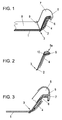
- FIG. 1 shows a cross section through a side region of a vehicle seat according to the invention
- FIG. 2 shows a plate with bubbles for use in a vehicle seat in a further embodiment according to the invention
- FIG. 3 is a view according to FIG Seat cover attachment
- Fig. 4 is a view similar to Fig. 1 with a different placement as well as type of bladder
- Fig. 5 is another embodiment of a bladder for use in a vehicle seat according to the invention.
- a vehicle seat shown schematically and simplified in Fig. 1 comprises a seat pan 1, on which, for example, in the region of the side edges of the backrest a substantially rigid plate 2 is articulated, so that in the connection area a kind of hinge 3 is defined to which the Plate 2 is pivotable relative to the seat pan 1.
- a kind of hinge 3 is defined to which the Plate 2 is pivotable relative to the seat pan 1.
- the plates 2 could also be made in one piece with the seat pan 1. Since the bladder 4 is pressed away from the hinge region 3 by the wedging action between the plate 2 and the seat pan 1, it is advantageously fastened there by a member subjected to tension, for example a flap-like side part of the bladder 4. Not shown in the drawing figures is an optional elastic element which can act on the plates 2 on the seat pan 1 with one of the spreading action of the fluidbehellbaren bladder 4 counteracting restoring force, so that the venting of the bladder 4 is supported and the return movement is performed faster.
- a member subjected to tension for example a flap-like side part of the bladder 4.
- an optional elastic element which can act on the plates 2 on the seat pan 1 with one of the spreading action of the fluidbehellbaren bladder 4 counteracting restoring force, so that the venting of the bladder 4 is supported and the return movement is performed faster.
- seat foam 8 can in this case also be connected to seat pan 1 in the hinge area 3, for example via a tufting 9, which moreover also serves for fastening cover 7 to seat pan 1.
- cover 7 is advantageously secured to the hinge region 3 opposite edge of the plate 2, as better seen in Fig. 3.
- the plate 2 is advantageously designed bent or kinked at least in the region opposite the hinge region 3.
- an aligned forward and in the direction of the contour of the seat surface is formed, on which preferably the bladder 5 is applied.
- the plate 2 with its outer, the hinge region 3 opposite edge of the edge of the seat pan 1 protrude and form the outer boundary of the seat pan 1, as well clearly in Fig. 3 can be seen.
- FIG. 2 an embodiment of a plate 2 according to the invention with two bubbles 4, 5a is shown on opposite sides of the plate 2. Also, this plate is bent or bent in the hinge region 3 opposite region.
- Bladder 5a designed as a folding bubble, in which two at least partially superposed contiguous sections are provided, which are also pneumatically connected and are parallel-ventilated. This results in a larger stroke than in a simple bubble the same footprint.
- This folding bladder 5a can also be connected to the lower bladder 4 via at least one line 6.
- at least one lobe or thread-like extension 10 can be provided, which can be used for fastening the bubble 5 a to the plate 2.
- Fig. 4 shows an arrangement in which the bladder 5 b between the seat cover 7 and seat foam 8, that is spaced from the surface of the plate 2, is arranged.
- This positioning can of course be provided for any type of bladder 5, 5a, 5b, 5c.
- Also embedding any bubbles 5, 5a, 5b, 5c in pockets, slits, cavities, etc. the seat foam 8 is possible.
- This solution with bubbles embedded in the seat foam 8 or between the seat foam 8 and the seat cover 7 can also be used if no pivotable plates 2 are introduced in the seat structure.
- the side adjustment can be increased.
- the bladder 5b provided on the outside of the plate 2 shown in Fig. 4 is in the form of a scarf blister, i.
- the scarf bladder 5b extends from the outer, the hinge region 3 opposite edge on the outside of the plate 2 in the direction of the hinge portion 3, beyond any bending or kink out, towards the inside.
- This bladder 5b may be pneumatically connected to the provided for pivoting the plate 2 bubbles 4.
- FIG. 5 shows an alternative embodiment of a bladder 5c with grooves of different lengths as stroke limiting means, which, in order to achieve a larger lifting height in the edge area, has a section 5d there, which is designed as a folding bladder.
- this portion 5d in the hinge region 3 opposite edge region of the plate 2 may be provided.
- this bubble can be introduced between seat foam 8 and cover 7.
Landscapes
- Engineering & Computer Science (AREA)
- Aviation & Aerospace Engineering (AREA)
- Transportation (AREA)
- Mechanical Engineering (AREA)
- Seats For Vehicles (AREA)
Applications Claiming Priority (1)
| Application Number | Priority Date | Filing Date | Title |
|---|---|---|---|
| AT0037505A AT501046B1 (de) | 2005-03-04 | 2005-03-04 | System zur automatischen sitzkonturverstellung, sowie sitz mit derartigem system |
Publications (2)
| Publication Number | Publication Date |
|---|---|
| EP1698511A1 true EP1698511A1 (fr) | 2006-09-06 |
| EP1698511B1 EP1698511B1 (fr) | 2010-12-22 |
Family
ID=36570510
Family Applications (1)
| Application Number | Title | Priority Date | Filing Date |
|---|---|---|---|
| EP06110030A Expired - Lifetime EP1698511B1 (fr) | 2005-03-04 | 2006-02-16 | Dispositif permettant de régler automatiquement le profil d'un siège, en particulier d'un siège |
Country Status (3)
| Country | Link |
|---|---|
| EP (1) | EP1698511B1 (fr) |
| AT (1) | AT501046B1 (fr) |
| DE (1) | DE502006008538D1 (fr) |
Cited By (8)
| Publication number | Priority date | Publication date | Assignee | Title |
|---|---|---|---|---|
| WO2008074373A1 (fr) * | 2006-12-16 | 2008-06-26 | Volkswagen Aktiengesellschaft | Siège de véhicule avec rembourrages pneumatiques de joues latérales |
| DE102007032449A1 (de) | 2007-07-12 | 2009-01-15 | GM Global Technology Operations, Inc., Detroit | Verfahren zur Steuerung einer Sitzeinrichtung und Sitzeinrichtung für ein Kraftfahrzeug |
| DE102007032448A1 (de) | 2007-07-12 | 2009-01-22 | GM Global Technology Operations, Inc., Detroit | Kraftfahrzeugsitz mit Seitenwangen und Verfahren zur Steuerung eines solchen Kraftfahrzeugsitzes |
| DE102007037378A1 (de) * | 2007-08-08 | 2009-02-12 | L & P Swiss Holding Company | Seitenwangenverstellung |
| DE102011116634A1 (de) * | 2011-10-20 | 2013-04-25 | Faurecia Autositze Gmbh | Rückenlehne eines Fahrzeugsitzes |
| US8602478B2 (en) | 2009-03-11 | 2013-12-10 | GM Global Technology Operations LLC | Vehicle seat with a variable-contour supporting surface |
| CN107458281A (zh) * | 2017-06-28 | 2017-12-12 | 重庆延锋安道拓汽车部件系统有限公司 | 带柔性座垫的自适应汽车座椅 |
| DE102023209027A1 (de) * | 2023-09-18 | 2025-03-20 | Volkswagen Aktiengesellschaft | Sitz mit einem über Luftkammern gespannten Bezug |
Families Citing this family (3)
| Publication number | Priority date | Publication date | Assignee | Title |
|---|---|---|---|---|
| AT502779A1 (de) * | 2005-10-27 | 2007-05-15 | Hoerbiger Automatisierungstech | System zur automatischen verstellung der sitz-kontur sowie sitz, insbesonders fahrzeugsitz für automobile, flugzeuge oder dergleichen |
| DE102016004206A1 (de) * | 2016-04-06 | 2017-07-06 | Daimler Ag | Vorrichtung zur Veränderung einer Kontur eines Fahrzeugsitzes und Fahrzeugsitz |
| DE102016220034A1 (de) * | 2016-10-14 | 2018-04-19 | Conti Temic Microelectronic Gmbh | Fluidkammermatte, Verfahren zu deren Herstellung und Fahrzeugsitz |
Citations (4)
| Publication number | Priority date | Publication date | Assignee | Title |
|---|---|---|---|---|
| US4965899A (en) | 1985-07-16 | 1990-10-30 | Okamoto Industries,Inc. | Air cushion for chair and chair utilizing the air cushion |
| GB2255905A (en) | 1989-04-28 | 1992-11-25 | Okamoto Ind Inc | Adjustable vehicle seat |
| US5280997A (en) * | 1991-03-05 | 1994-01-25 | Mercedes-Benz Ag | Motor vehicle seat |
| DE19938697A1 (de) * | 1999-08-14 | 2001-02-15 | Volkswagen Ag | Fahrzeugsitz |
-
2005
- 2005-03-04 AT AT0037505A patent/AT501046B1/de not_active IP Right Cessation
-
2006
- 2006-02-16 EP EP06110030A patent/EP1698511B1/fr not_active Expired - Lifetime
- 2006-02-16 DE DE502006008538T patent/DE502006008538D1/de not_active Expired - Lifetime
Patent Citations (4)
| Publication number | Priority date | Publication date | Assignee | Title |
|---|---|---|---|---|
| US4965899A (en) | 1985-07-16 | 1990-10-30 | Okamoto Industries,Inc. | Air cushion for chair and chair utilizing the air cushion |
| GB2255905A (en) | 1989-04-28 | 1992-11-25 | Okamoto Ind Inc | Adjustable vehicle seat |
| US5280997A (en) * | 1991-03-05 | 1994-01-25 | Mercedes-Benz Ag | Motor vehicle seat |
| DE19938697A1 (de) * | 1999-08-14 | 2001-02-15 | Volkswagen Ag | Fahrzeugsitz |
Cited By (10)
| Publication number | Priority date | Publication date | Assignee | Title |
|---|---|---|---|---|
| WO2008074373A1 (fr) * | 2006-12-16 | 2008-06-26 | Volkswagen Aktiengesellschaft | Siège de véhicule avec rembourrages pneumatiques de joues latérales |
| DE102007032449A1 (de) | 2007-07-12 | 2009-01-15 | GM Global Technology Operations, Inc., Detroit | Verfahren zur Steuerung einer Sitzeinrichtung und Sitzeinrichtung für ein Kraftfahrzeug |
| DE102007032448A1 (de) | 2007-07-12 | 2009-01-22 | GM Global Technology Operations, Inc., Detroit | Kraftfahrzeugsitz mit Seitenwangen und Verfahren zur Steuerung eines solchen Kraftfahrzeugsitzes |
| DE102007037378A1 (de) * | 2007-08-08 | 2009-02-12 | L & P Swiss Holding Company | Seitenwangenverstellung |
| WO2009018977A3 (fr) * | 2007-08-08 | 2009-04-16 | L&P Swiss Holding Co | Déplacement de joues latérales |
| US8602478B2 (en) | 2009-03-11 | 2013-12-10 | GM Global Technology Operations LLC | Vehicle seat with a variable-contour supporting surface |
| DE102011116634A1 (de) * | 2011-10-20 | 2013-04-25 | Faurecia Autositze Gmbh | Rückenlehne eines Fahrzeugsitzes |
| CN107458281A (zh) * | 2017-06-28 | 2017-12-12 | 重庆延锋安道拓汽车部件系统有限公司 | 带柔性座垫的自适应汽车座椅 |
| CN107458281B (zh) * | 2017-06-28 | 2023-10-20 | 安道拓(重庆)汽车部件有限公司 | 带柔性座垫的自适应汽车座椅 |
| DE102023209027A1 (de) * | 2023-09-18 | 2025-03-20 | Volkswagen Aktiengesellschaft | Sitz mit einem über Luftkammern gespannten Bezug |
Also Published As
| Publication number | Publication date |
|---|---|
| EP1698511B1 (fr) | 2010-12-22 |
| AT501046B1 (de) | 2006-06-15 |
| DE502006008538D1 (de) | 2011-02-03 |
| AT501046A4 (de) | 2006-06-15 |
Similar Documents
| Publication | Publication Date | Title |
|---|---|---|
| DE102006037521B4 (de) | System zur automatischen Verstellung von Sitzen, insbesondere von Fahrzeugsitzen sowie Sitz für Automobile, Flugzeuge oder dergleichen mit einem solchen System | |
| DE102011121120B3 (de) | Kopfstütze für Kraftfahrzeugsitze | |
| EP1973448B1 (fr) | Soutien de lordose | |
| DE102008047249A1 (de) | Rückenlehnenstruktur für einen Kraftfahrzeugsitz | |
| DE102008051072A1 (de) | Kraftfahrzeugsitz mit Lendenstütze für ein Anti-Schleudertraumasystem | |
| EP1698511B1 (fr) | Dispositif permettant de régler automatiquement le profil d'un siège, en particulier d'un siège | |
| EP1423296A1 (fr) | Element de support pour le rembourrage d'un siege de vehicule automobile | |
| DE19825225A1 (de) | Wölbungsverstellbare Stütze, insbesondere Lordosenstütze, für Sitze und Liegen aller Art | |
| DE102014214738A1 (de) | Multikonturen-blasensystem | |
| DE10321744B4 (de) | Kopfstützenmechanismus | |
| DE112013007678T5 (de) | SMA-Ventil zur Steuerung von Druckluftzufuhr zu einer Luftzelle in einem Fahrzeugsitz | |
| DE102019122533A1 (de) | Abdeckungsvorrichtung für Fahrzeugsitze | |
| DE102018117994A1 (de) | Torsionsstabaufhängung für ein fahrzeug, und torsionsstab für ein fahrzeug | |
| DE202012008758U1 (de) | Kraftfahrzeugsitzeinrichtung | |
| DE2902246A1 (de) | Kopfstuetze | |
| DE102007003642A1 (de) | Rückenlehne für einen Fahrzeugsitz | |
| WO2012022605A1 (fr) | Siège de véhicule avec dossier bombé | |
| EP3626521B1 (fr) | Dispositif de couverture pour sièges de véhicule | |
| DE102009021654A1 (de) | Fahrzeugsitz | |
| DE3718528A1 (de) | Sitz, insbesondere fuer kraftfahrzeuge | |
| AT412962B (de) | Befestigungsanordnung für aufblasbare körper | |
| DE102009041457A1 (de) | Anordnung einer Verstelleinheit für eine Seitenwange an einem Sitz | |
| DE102010053190A1 (de) | Rückenlehnenstruktur für einen Kraftfahrzeugsitz | |
| DE4007929C2 (fr) | ||
| DE10322190B3 (de) | Lordosenstützkorb |
Legal Events
| Date | Code | Title | Description |
|---|---|---|---|
| PUAI | Public reference made under article 153(3) epc to a published international application that has entered the european phase |
Free format text: ORIGINAL CODE: 0009012 |
|
| AK | Designated contracting states |
Kind code of ref document: A1 Designated state(s): AT BE BG CH CY CZ DE DK EE ES FI FR GB GR HU IE IS IT LI LT LU LV MC NL PL PT RO SE SI SK TR |
|
| AX | Request for extension of the european patent |
Extension state: AL BA HR MK YU |
|
| 17P | Request for examination filed |
Effective date: 20070305 |
|
| AKX | Designation fees paid |
Designated state(s): DE FR |
|
| 17Q | First examination report despatched |
Effective date: 20070420 |
|
| RAP1 | Party data changed (applicant data changed or rights of an application transferred) |
Owner name: HOERBIGER AUTOMATISIERUNGSTECHNIK HOLDING GMBH |
|
| RAP1 | Party data changed (applicant data changed or rights of an application transferred) |
Owner name: HOERBIGER AUTOMOTIVE KOMFORTSYSTEME GMBH |
|
| GRAP | Despatch of communication of intention to grant a patent |
Free format text: ORIGINAL CODE: EPIDOSNIGR1 |
|
| GRAS | Grant fee paid |
Free format text: ORIGINAL CODE: EPIDOSNIGR3 |
|
| GRAA | (expected) grant |
Free format text: ORIGINAL CODE: 0009210 |
|
| AK | Designated contracting states |
Kind code of ref document: B1 Designated state(s): DE FR |
|
| REF | Corresponds to: |
Ref document number: 502006008538 Country of ref document: DE Date of ref document: 20110203 Kind code of ref document: P |
|
| REG | Reference to a national code |
Ref country code: DE Ref legal event code: R096 Ref document number: 502006008538 Country of ref document: DE Effective date: 20110203 |
|
| PLBE | No opposition filed within time limit |
Free format text: ORIGINAL CODE: 0009261 |
|
| STAA | Information on the status of an ep patent application or granted ep patent |
Free format text: STATUS: NO OPPOSITION FILED WITHIN TIME LIMIT |
|
| 26N | No opposition filed |
Effective date: 20110923 |
|
| REG | Reference to a national code |
Ref country code: DE Ref legal event code: R097 Ref document number: 502006008538 Country of ref document: DE Effective date: 20110923 |
|
| REG | Reference to a national code |
Ref country code: FR Ref legal event code: PLFP Year of fee payment: 11 |
|
| REG | Reference to a national code |
Ref country code: FR Ref legal event code: PLFP Year of fee payment: 12 |
|
| REG | Reference to a national code |
Ref country code: DE Ref legal event code: R079 Ref document number: 502006008538 Country of ref document: DE Free format text: PREVIOUS MAIN CLASS: B60N0002440000 Ipc: B60N0002900000 |
|
| REG | Reference to a national code |
Ref country code: FR Ref legal event code: PLFP Year of fee payment: 13 |
|
| PGFP | Annual fee paid to national office [announced via postgrant information from national office to epo] |
Ref country code: DE Payment date: 20250122 Year of fee payment: 20 |
|
| PGFP | Annual fee paid to national office [announced via postgrant information from national office to epo] |
Ref country code: FR Payment date: 20250122 Year of fee payment: 20 |
|
| REG | Reference to a national code |
Ref country code: DE Ref legal event code: R071 Ref document number: 502006008538 Country of ref document: DE |