EP1698802A2 - Dispositif de blocage de câble - Google Patents
Dispositif de blocage de câble Download PDFInfo
- Publication number
- EP1698802A2 EP1698802A2 EP06251155A EP06251155A EP1698802A2 EP 1698802 A2 EP1698802 A2 EP 1698802A2 EP 06251155 A EP06251155 A EP 06251155A EP 06251155 A EP06251155 A EP 06251155A EP 1698802 A2 EP1698802 A2 EP 1698802A2
- Authority
- EP
- European Patent Office
- Prior art keywords
- cable
- retention member
- entrance port
- guide
- entrance
- Prior art date
- Legal status (The legal status is an assumption and is not a legal conclusion. Google has not performed a legal analysis and makes no representation as to the accuracy of the status listed.)
- Withdrawn
Links
- 230000014759 maintenance of location Effects 0.000 claims abstract description 151
- 230000037361 pathway Effects 0.000 claims abstract description 18
- 230000000295 complement effect Effects 0.000 claims description 18
- 239000002184 metal Substances 0.000 description 5
- 239000000725 suspension Substances 0.000 description 3
- 229910001335 Galvanized steel Inorganic materials 0.000 description 2
- 239000008397 galvanized steel Substances 0.000 description 2
- 238000009434 installation Methods 0.000 description 2
- JEIPFZHSYJVQDO-UHFFFAOYSA-N iron(III) oxide Inorganic materials O=[Fe]O[Fe]=O JEIPFZHSYJVQDO-UHFFFAOYSA-N 0.000 description 2
- 238000004519 manufacturing process Methods 0.000 description 2
- 239000000463 material Substances 0.000 description 2
- 239000011800 void material Substances 0.000 description 2
- 238000010276 construction Methods 0.000 description 1
- 238000003780 insertion Methods 0.000 description 1
- 230000037431 insertion Effects 0.000 description 1
- 238000009436 residential construction Methods 0.000 description 1
- 238000005476 soldering Methods 0.000 description 1
Images




Classifications
-
- F—MECHANICAL ENGINEERING; LIGHTING; HEATING; WEAPONS; BLASTING
- F16—ENGINEERING ELEMENTS AND UNITS; GENERAL MEASURES FOR PRODUCING AND MAINTAINING EFFECTIVE FUNCTIONING OF MACHINES OR INSTALLATIONS; THERMAL INSULATION IN GENERAL
- F16G—BELTS, CABLES, OR ROPES, PREDOMINANTLY USED FOR DRIVING PURPOSES; CHAINS; FITTINGS PREDOMINANTLY USED THEREFOR
- F16G11/00—Means for fastening cables or ropes to one another or to other objects; Caps or sleeves for fixing on cables or ropes
- F16G11/14—Devices or coupling-pieces designed for easy formation of adjustable loops, e.g. choker hooks; Hooks or eyes with integral parts designed to facilitate quick attachment to cables or ropes at any point, e.g. by forming loops
-
- F—MECHANICAL ENGINEERING; LIGHTING; HEATING; WEAPONS; BLASTING
- F16—ENGINEERING ELEMENTS AND UNITS; GENERAL MEASURES FOR PRODUCING AND MAINTAINING EFFECTIVE FUNCTIONING OF MACHINES OR INSTALLATIONS; THERMAL INSULATION IN GENERAL
- F16G—BELTS, CABLES, OR ROPES, PREDOMINANTLY USED FOR DRIVING PURPOSES; CHAINS; FITTINGS PREDOMINANTLY USED THEREFOR
- F16G11/00—Means for fastening cables or ropes to one another or to other objects; Caps or sleeves for fixing on cables or ropes
- F16G11/10—Quick-acting fastenings; Clamps holding in one direction only
- F16G11/105—Clamps holding in one direction only
- F16G11/106—Clamps holding in one direction only using a toothed surface
-
- Y—GENERAL TAGGING OF NEW TECHNOLOGICAL DEVELOPMENTS; GENERAL TAGGING OF CROSS-SECTIONAL TECHNOLOGIES SPANNING OVER SEVERAL SECTIONS OF THE IPC; TECHNICAL SUBJECTS COVERED BY FORMER USPC CROSS-REFERENCE ART COLLECTIONS [XRACs] AND DIGESTS
- Y10—TECHNICAL SUBJECTS COVERED BY FORMER USPC
- Y10T—TECHNICAL SUBJECTS COVERED BY FORMER US CLASSIFICATION
- Y10T24/00—Buckles, buttons, clasps, etc.
- Y10T24/39—Cord and rope holders
- Y10T24/3969—Sliding part or wedge
Definitions
- the present invention relates to gripping devices and, in particular, to a device for releasably gripping a cable.
- a suspension cable such as a metallic or rubber rope or wire is used to aid in this suspension. It is typically attached on one end to the structural member, inserted through a wedge device, looped around the equipment, and finally the cable is inserted through the wedge device a second time to retain the cable in place and suspend the equipment that is supported by the cable.
- Prior wedge devices have inner jaws or retention members that can twist within the housing and thereby weaken their grip on the cable. High stress is also created on the housing because the jaws do not move parallel to the cable within the housing.
- the present invention eliminates the above difficulties and disadvantages by providing an improved device for gripping a cable having a free end.
- the device comprises a first entrance port for receiving the free end of the cable and a first exit port that is in communication with the first entrance port from where the free end of the cable exits the device.
- a second entrance port is provided for receiving the free end of the cable after it leaves the exit port and is bundled through an eyelet, for example, that is attached to equipment or bundled around a group of generally linear items for shipping such as logs or electrical distribution poles.
- a second exit port is in communication with the second entrance port where the free end of the cable exits the device a second time.
- first cable guide forms an arcuate pathway between the first entrance port and the first exit port.
- the first cable guide also includes a first guide rail secured therein.
- a first retention member is slidably disposed within the first cable guide such that the first retention member slides axially within the device only upon entrance of the cable within the first cable guide or when the cable is pulled toward the first entrance port.
- the first retention member further includes an arcuate grip member integrally formed therewith and a retention channel integrally formed therewith that is complementary in shape to the first guide rail and slidably mounted thereon such that only axial movement of the first retention member is permitted within the first cable guide.
- the first retention member includes a rounded surface and a grip surface that is in communication with the rounded surface. The cable abuts the rounded surface upon entrance into the first entrance port and simultaneously the cable is deflected and the retention member is biased axially, The grip surface contacts the cable when the cable is pulled toward the first entrance port.
- a second cable guide forms an arcuate pathway between the second entrance port and the second exit port.
- the second cable guide also includes a second guide rail secured therein.
- a second retention member is slidably disposed within the second cable guide such that the second retention member slides axially within the device only upon entrance of the cable within the second cable guide or when the cable is pulled toward the second entrance port.
- the second retention member includes an arcuate grip member integrally formed therewith and a retention channel integrally formed therewith that is complementary in shape to the second guide rail and slidably mounted thereon such that only axial movement of the second retention member is permitted within the second cable guide.
- the second retention member includes a rounded surface and a grip surface that is in communication with the rounded surface. The cable abuts the rounded surface upon entrance into the second entrance port and simultaneously the cable is deflected away from the second retention member and the second retention member is biased axially. The grip surface contacts the cable when the cable is pulled toward the second entrance port.
- the first cable guide has a convex portion and a concave portion.
- the grip member of the first retention member is slidably positioned adjacent the concave portion of the first cable guide when the cable is inserted into the first cable guide and slidably positioned adjacent the convex portion of the first cable guide when the cable is pulled toward the first entrance port such that the cable is wedged between the grip member and the convex portion of the first cable guide.
- the second cable guide also has a convex portion and a concave portion.
- the grip member of the second retention member is slidably positioned adjacent the concave portion of the second cable guide when the cable is inserted into the second cable guide and slidably positioned adjacent the convex portion of the second cable guide when the cable is pulled toward the second entrance port such that the cable is wedged between the grip member and the convex portion of the second cable guide.
- the first cable guide includes a first guide rail secured therein and the first retention member includes a retention channel integrally formed therewith that is complementary in shape to the first guide rail and slidably mounted thereon such that only axial movement of the first retention member is permitted within the first cable guide upon entrance of the cable within the first cable guide or when the cable is pulled toward the first entrance port.
- the second cable guide includes a second guide rail secured therein and the second retention member includes a retention channel integrally formed therewith that is complementary in shape to the second guide rail and slidably mounted thereon such that only axial movement of the second retention member is permitted within the second cable guide upon entrance of the cable within the second cable guide or when the cable is pulled toward the second entrance port.
- a release means is provided that comprises two apertures into which an actuation member is inserted for moving the retention member and disengaging the first retention member and the second retention member from the cable.
- An alternate device comprises a first entrance port for receiving the free end of the cable and a first exit port that is in communication with the first entrance port from where the free end of the cable exits the device.
- a second entrance port is provided for receiving the free end of the cable after it leaves the exit port and is bundled through an eyelet, for example, that is attached to equipment or bundled around a group of generally linear items for shipping such as logs or electrical distribution poles.
- a second exit port is in communication with the second entrance port where the free end of the cable exits the device a second time.
- a first cable guide forms a pathway between the first entrance port and the first exit port that is preferably angled but could be straight. While a second cable guide forms a pathway between the second entrance port and the second exit port.
- a dividing wall is located between the first cable guide and the second guide, the dividing wall forming part of the first cable guide and the second guide.
- a first retention member is slidably disposed within the first cable guide and includes a grip member integrally formed therewith and having a grip surface angled in parallel relationship to the dividing wall such that the grip surface contacts the cable and wedges it against the dividing wall when the cable is pulled toward the first entrance port.
- a second retention member is slidably disposed within the second cable guide and including a grip member integrally formed therewith.
- the grip member has a grip surface angled in parallel relationship to the dividing wall such that the grip surface contacts the cable and wedges it against the dividing wall when the cable is pulled toward the second entrance port.
- the grip surface of the first retention member and the second retention member are complimentary in shape to the cable.
- the first cable guide includes a first shaft adjacent thereto and the first retention member includes a guide member integrally formed therewith that is complementary in shape to the first shaft and slidably mounted thereon such that only axial movement of the first retention member is permitted within the first cable guide upon entrance of the cable within the first entrance port or when the cable is pulled toward the first entrance port.
- the second cable guide includes a second shaft adjacent thereto and the second retention member includes a guide member integrally formed therewith that is complementary in shape to the second shaft and slidably mounted thereon such that only axial movement of the second retention member is permitted within the second cable guide upon entrance of the cable within the second entrance port or when the cable is pulled toward the second entrance port,
- a release means is provided that comprises two apertures into which an actuation member is inserted for moving the retention member and disengaging the first retention member and the second retention member from the cable.
- FIG. 1 Shown in FIG. 1 is a system for hanging equipment 22 or bundling a group of objects such as electrical distribution poles 78 (Shown in FIG. 8) for shipping.
- the system includes a cable 10 that may be secured to a structural member 18 such as a support beam by a hook 16, the hook 16 being secured to an attachment end 14 of the cable 10 via a crimp device or soldering.
- the hook 16 engages an eyelet 20 that is mounted on the structural member 18.
- the free end 12 of the cable 10 is inserted through device 30 and then inserted through an eye 24 that is secured to the equipment 22 and finally back through device 30 that seoures the cable 10 from slipping and allows the equipment 22 to be suspended in air.
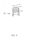
- the present system and device have many applications. Another application is shown in FIG. 8, which displays a truck 76 that is carrying a load of logs of electrical distribution poles 78. In this application device 30 and cable 10 are used to bundle poles 78.
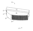
- the device 30 is preferably constructed of a rust inhibited metal such as galvanized steel, but can also be constructed of a thermoformed plastic, Rivets 36 fit into apertures 30, as shown in FIG. 3, and are heated to stake the first shell 32 to the second shell 34.
- a rust inhibited metal such as galvanized steel
- Rivets 36 fit into apertures 30, as shown in FIG. 3, and are heated to stake the first shell 32 to the second shell 34.
- the device 30 includes a first entrance port 42 for receiving the free end 12 of the cable 10.
- the first entrance port 42 is angled or beveled to aid in entrance of the free end 12 of cable 10.
- device 30 includes a first exit port 44 that is in communication with the first entrance port 42.
- the first exit port 44 is where the free end 12 of the cable 10 exits the device 30 a first time.
- a second entrance port 46 is provided for receiving the free end 12 of the cable 10 after it leaves the first exit port 44 and is inserted through the eye 24, for example, that is attached to the equipment 22 or bundled around a group of generally linear items for shipping such items as logs or electrical distribution poles 78 as shown in FIG. 8.
- a second exit port 48 is in communication with the second entrance port 46 where the free end 12 of the cable 10 exits the device 30 a second time. As shown in FIGS. 2 and 3, the first exit port 44 and second exit port 48 are generally rectangular in shape to allow cable 10 to move laterally.
- a first cable guide 80 is formed within device 30 and includes a first guide rail 84 secured therein.
- First guide rail 84 has an 1-shaped cross section.
- a first retention member 58 is slidably disposed within the first cable guide 80 on the first guide rail 84 such that it can only move axially.
- the first retention member 58 further includes retention channels 62 integrally formed therewith that are complementary in shape to at least part of the first guide rail 84 in both the first shell 32 and the second shell 34, and slidably mounted thereon such that only axial movement of the first retention member 58 is permitted within the first cable guide 80 upon entrance of the cable 10 within the first entrance port 42 or when cable 10 is pulled toward the first entrance port 42.
- the retention channels 62 are generally U-shaped and formed between an arcuate grip member 66 that is integrally formed on the first retention member 58 and guide member 64 as shown in FIGS. 3 and 4.
- Round surface 72 is disposed on one side of grip member 66.
- Grip surface 68 is in communication with round surface 72 and is cut into grip member 66 along approximately sixty percent of grip member 66 that is disposed opposite guide member 64.
- cable 10 is inserted into first entrance port 42
- cable 10 is deflected off rounded surface 72 away from the first retention member 58 and first retention member 58 is biased toward first exit port 44.
- Grip surface 68 contacts cable 10 only when cable 10 is pulled toward the first entrance port 42.
- the first cable guide 80 forms an arcuate pathway between the first entrance port 42 and the first exit port 44 and has a convex portion 56 and a concave portion 54.
- the grip member 66 of the first retention member 58 is slidably positioned adjacent at least part of the concave portion 54 of the first cable guide 80 when the cable 10 is inserted into the first entrance port 42 and is slidably positioned adjacent the convex portion 56 of the first cable guide 80 when the cable 10 is pulled toward the first entrance port 42 such that the cable 10 is wedged between the grip member 66 and the convex portion 56 of the first cable guide 80.
- grip surface 68 contacts cable 10 to further prevent slippage of the cable 10 within device 30 along the longitudinal area of the grip surface 68.
- the device 30 further includes a second entrance port 46 for receiving the free end 12 of the cable 10.
- the second entrance port 46 is angled or beveled to aid in entrance of the free end 12 of cable 10.
- device 30 includes a second exit port 48 that is in communication with the second entrance port 46.
- the second exit port 48 is where the free end 12 of the cable 10 exits the device 30 a second time.
- a second entrance port 46 is provided for receiving the free end 12 of the cable 10 after it leaves the first exit port 44 and is inserted through the eye 24, for example, that is attached to the equipment 22 or bundled around a group of generally linear items for shipping such items as logs or electrical distribution poles 78 as shown in FIG. 8.
- the second exit port 48 is in communication with the second entrance port 46 where the free end 12 of the cable 10 exits the device 30 a second time. As shown in FIGS. 2 and 3, the first exit port 44 and second exit port 48 are generally rectangular in shape to allow cable 10 to move laterally.
- cable release aperture 40 is disposed in the first shell 32 and the second shell 34 for releasing the grip of retention members 58, 60 on cable 10 by insertion of an actuation member 50 therein,
- aperture 40 is in communication with track 74 that is formed adjacent to first guide rail 84 and second guide rail 86.
- the actuation member 50 is preferably a plastic, metallic or wooden rod that is inserted into aperture 40 and abuts first retention member 58 or second retention member 60. When contact is made between actuation member 50 and the first retention member 58 or second retention member 60, the retention member is pushed toward the concave portion 54 of the first cable guide 80 or second cable guide 82 thereby releasing wedging pressure on cable 10 and allowing it to be removed from device 30.
- a second cable guide 82 is formed within device 30 and includes a second guide rail 86 secured therein.
- Second guide rail 86 has an I-shaped cross section.
- a second retention member 60 is slidably disposed within the second cable guide 82 on the second guide rail 84. No internal pressure is applied to the second cable guide 82 such as a spring, but rather it frictionally glides along the second guide rail 86 when pressure from cable 10 is applied against the second guide rail 86 during installation of cable 10.
- the second retention member 60 further includes retention channels 62 integrally formed therewith that are complementary in shape to at least part of the second guide rail 86 in both the second shell 32 and the second shell 34, and slidably mounted thereon such that only axial movement of the second retention member 60 is permitted within the second cable guide 82 upon entrance of the cable 10 within the second entrance port 46 or when cable 10 is pulled toward the second entrance port 46.
- the retention channels 62 are generally U-shaped and formed between an arcuate grip member 66 that is integrally formed on the second retention member 60 and guide member 64 as shown in FIGS, 3 and 4. Round surface 72 is disposed on one side of the grip member 66.
- Grip surface 68 is in communication with round surface 72 and is cut into grip member 66 along approximately sixty percent of grip member 66 that is disposed opposite guide member 64.
- the grip surface 68 can be of any configuration to grip the cable 10, but is preferably constructed of abutting pyramid shapes. In operation, when cable 10 is inserted into second entrance port 46, cable 10 is deflected off rounded surface 72 away from the second retention member 58 and second retention member 60 is biased toward second exit port 48, Grip surface 68 contacts cable 10 only when cable 10 is pulled toward the second entrance port 46 and does not contact cable 10 when it is inserted into second entrance port 46 since cable 10 is deflected off rounded surface 72.
- the second cable guide 82 forms an arcuate pathway between the second entrance port 46 and the second exit port 48 and has a convex portion 56 and a concave portion 54.
- the grip member 66 of the second retention member 60 is slidably positioned adjacent at least part of the concave portion 54 of the second cable guide 82 when the cable 10 is inserted into the second entrance port 46 and is slidably positioned adjacent the convex portion 56 of the second cable guide 82 when the cable 10 is pulled toward the second entrance port 46 such that the cable 10 is wedged between the grip member 66 and the convex portion 56 of the second cable guide 82.
- grip surface 68 contacts cable 10 to further prevent slippage of the cable 10 within device 30 along the longitudinal area of grip surface 68.
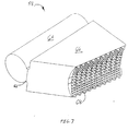
- FIGS. 5-7 An alternate device 30 is shown in FIGS. 5-7.
- the device 30 is preferably constructed of a rust inhibited metal such as galvanized steel, but can also be constructed of a thermoformed plastic. Rivets 36 fit into apertures 30, as shown in FIG. 3, and are heated to stake the first shell 32 to the second shell 34.
- the device 30 includes a first entrance port 42 for receiving the free end 12 of the cable 10.
- the first entrance port 42 is angled to aid in entrance of the free end 12 of cable 10.
- device 30 includes a first exit port 44 that is in communication with the first entrance port 42.
- the first exit port 44 is where the free end 12 of the cable 10 exits the device 30 a first time.
- a second entrance port 46 is provided for receiving the free end 12 of the cable 10 after it leaves the first exit port 44 and is inserted through the eye 24, for example, that is attached to the equipment 22 or bundled around a group of generally linear items for shipping such items as logs or electrical distribution poles 78 as shown in FIG, 8.
- a second exit port 48 is in communication with the second entrance port 46 where the free end 12 of the cable 10 exits the device 30 a second time. As shown in FIGS. 5 and 6, the first exit port 44 and second exit port 48 are generally rectangular in shape to allow cable 10 to move laterally once cable 10 exits device 30.
- a first cable guide 80 forms a pathway between the first entrance port 42 and the first exit port 44 that widens toward the first exit port 44.
- a second cable guide 82 forms a pathway between the second entrance port 46 and widens toward the second exit port 48.
- a dividing wall 52 is preferable constructed of the same material as first shell 32 and second shell 34 and located between the first cable guide 80 and the second cable guide 82.
- the dividing wall 52 is preferably angled at 45 degrees but could be straight or angled at a greater or lesser degree.
- the dividing wall 52 forms part of the first cable guide 80 and the second cable guide 82.
- a first retention member 58 is provided that is preferably formed of metal or thermoformed plastic, and is slidably disposed within the first cable guide 80.
- a first shaft 74 is disposed adjacent the first cable guide 80 and is a cylindrical cavity.
- the first retention member 58 includes a retention channel 62 integrally formed therewith and a guide member 64 that is complementary in shape to the first guide rail 84 and slidably mounted thereon.
- Spring 70 is attached between one end of track 74 and guide member 64 thereby creating opposite force on first retention member 58 when axially biased. Since grip member 64 is cylindrical in shape and is complimentary to first shaft 74, which forms a cylindrical void into which the grip member 64 moves, only axial movement of the first retention member 58 is permitted within the first cable guide 80.
- the first retention member 58 includes a grip member 66 integrally formed therewith.
- Grip member 66 has a grip surface 68 angled in parallel relationship to the dividing wall 52 such that the grip surface 68 contacts the cable 10 and wedges it against the dividing wall 52 when the cable 10 is pulled toward the first entrance port 42.
- grip surface 68 is concave in shape and has a plurality of abutting pyramid shapes formed thereon for conforming to the annular shape of cable 10 and gripping its surface along a longitudinal section.
- first retention member 58 In operation, upon entrance of the cable 10 within the first entrance port 42, cable 10 will abut angled surface 28 as shown in FIG. 6 simultaneously deflect away from retention member 58 and bias first retention member 58 axially toward first exit port 44. Cable 10 slides past grip surface 68 with only minimal retention force being applied to cable 10 since grip member 66 has been slid into the wide portion of first cable guide 80. When cable 10 is pulled toward the first entrance port 42, first retention member 58 is biased toward the first entrance port 42 only enough to allow for cable 10 to be tightly wedged between grip surface 68 and dividing wall 52.
- a second retention member 60 is provided that is preferably formed of metal or thermoformed plastic, and is slidably disposed within the second cable guide 82.
- a second shaft 75 is disposed adjacent the second cable guide 82 and is a cylindrical cavity.
- the second retention member 60 includes a retention channel 62 integrally formed therewith and a guide member 64 that is complementary in shape to the second guide rail 86 and slidably mounted thereon.
- Spring 70 is attached between one end of second shaft 75 and guide member 64 thereby creating opposite force on first retention member 58 when axially biased. Since grip member 64 is cylindrical in shape and is complimentary to second shaft 75, which forms a cylindrical void into which the grip member 64 moves, only axial movement of the second retention member 60 is permitted within the second cable guide 82.
- the second retention member 60 includes a grip member 66 integrally formed therewith.
- Grip member 66 has a grip surface 68 angled in parallel relationship to the dividing wall 52 such that the grip surface 68 contacts the cable 10 and wedges it against the dividing wall 52 when cable 10 is pulled toward the second entrance port 46.
- grip surface 68 is concave in shape and has a plurality of abutting pyramid shapes formed thereon for conforming to the annular shape of cable 10 and gripping its surface along a longitudinal section.
- cable 10 In operation, upon entrance of the cable 10 within the second entrance port 46, cable 10 will abut angled surface 28 as shown in FIG. 6 simultaneously deflect away from retention member 60 and bias second retention member 60 axially toward second exit port 48, Cable 10 slides past grip surface 68 with only minimal retention force being applied to cable 10 since grip member 66 has been slid into the wide portion of second cable guide 82.
- second retention member 60 When cable 10 is pulled toward the second entrance port 46, second retention member 60 is biased toward the second entrance port 46 only enough to allow for cable 10 to be tightly wedged between grip surface 68 and dividing wall 52.
- release means comprises two apertures 40 into which an actuation member 50, which is preferably a rod, is inserted for moving the retention member 60 and disengaging the first retention member 58 and the second retention member 60 from the cable 10.
- actuation member 50 which is preferably a rod
Landscapes
- Engineering & Computer Science (AREA)
- General Engineering & Computer Science (AREA)
- Mechanical Engineering (AREA)
- Installation Of Indoor Wiring (AREA)
- Load-Engaging Elements For Cranes (AREA)
Applications Claiming Priority (1)
| Application Number | Priority Date | Filing Date | Title |
|---|---|---|---|
| US65862805P | 2005-03-04 | 2005-03-04 |
Publications (2)
| Publication Number | Publication Date |
|---|---|
| EP1698802A2 true EP1698802A2 (fr) | 2006-09-06 |
| EP1698802A3 EP1698802A3 (fr) | 2007-01-10 |
Family
ID=36572014
Family Applications (1)
| Application Number | Title | Priority Date | Filing Date |
|---|---|---|---|
| EP06251155A Withdrawn EP1698802A3 (fr) | 2005-03-04 | 2006-03-03 | Dispositif de blocage de câble |
Country Status (3)
| Country | Link |
|---|---|
| US (1) | US20060196016A1 (fr) |
| EP (1) | EP1698802A3 (fr) |
| CA (1) | CA2538551A1 (fr) |
Cited By (4)
| Publication number | Priority date | Publication date | Assignee | Title |
|---|---|---|---|---|
| EP2213905A1 (fr) * | 2009-01-28 | 2010-08-04 | Thomas & Betts International, Inc. | Dispositif de blocage de câble |
| US8001660B2 (en) | 2007-10-31 | 2011-08-23 | Thomas & Betts International, Inc | Cable gripping device |
| WO2013114207A1 (fr) * | 2012-01-30 | 2013-08-08 | Revision Military S.A.R.L. | Système de fixation et procédé de fixation d'un premier et d'un second objet avec ledit système de fixation |
| US8578566B2 (en) | 2007-10-31 | 2013-11-12 | Thomas & Betts International, Inc. | Cable gripping device |
Families Citing this family (13)
| Publication number | Priority date | Publication date | Assignee | Title |
|---|---|---|---|---|
| US8171695B2 (en) * | 2007-01-19 | 2012-05-08 | Thomas & Butts International, Inc. | Arm connection for a structural member |
| GB2492621B (en) * | 2011-07-08 | 2014-05-21 | Gripple Ltd | Gripping arrangement and gripping assembly |
| US9622546B2 (en) * | 2011-10-14 | 2017-04-18 | Moldex-Metric, Inc. | Clamp for adjustably joining the ends of a strap |
| US9339408B2 (en) * | 2011-10-21 | 2016-05-17 | Endur ID, Inc. | Clasp for securing flexible bands |
| US10441037B2 (en) * | 2011-10-21 | 2019-10-15 | Endur Id, Inc | Clasp for securing flexible bands |
| MY183510A (en) * | 2014-02-07 | 2021-02-23 | Mega Fortris Malaysia Sdn Bhd | A cable lock and seal device |
| WO2015156996A1 (fr) * | 2014-04-11 | 2015-10-15 | E.J. Brooks Company | Dispositif d'inviolabilité thermoplastique à évidement de verrouillage recouvert |
| US11098502B2 (en) * | 2014-05-15 | 2021-08-24 | Steven Joseph Jaworski | Tamper proof cable lock |
| US11297906B2 (en) | 2018-11-09 | 2022-04-12 | Endur ID, Inc. | Flexible band clasp with communication device |
| US11308748B2 (en) | 2019-05-15 | 2022-04-19 | Endur ID, Inc. | Flexible identification band with cut detection |
| US12044040B2 (en) * | 2021-04-02 | 2024-07-23 | Brady Worldwide, Inc. | Cable lockout device |
| GB202114402D0 (en) * | 2021-10-08 | 2021-11-24 | Gripple Ltd | Clamping device |
| USD1080443S1 (en) | 2022-08-12 | 2025-06-24 | Endur ID, Inc. | Clasp |
Family Cites Families (30)
| Publication number | Priority date | Publication date | Assignee | Title |
|---|---|---|---|---|
| US749896A (en) * | 1904-01-19 | Cable-grip clamp | ||
| US1165785A (en) * | 1915-12-28 | Louis H Knoche | Package-tie. | |
| US1692993A (en) * | 1928-11-27 | Wire-rope clamp | ||
| US1069135A (en) * | 1911-09-11 | 1913-08-05 | John Heberling | Rope-tie. |
| US1139595A (en) * | 1914-02-24 | 1915-05-18 | Fred Starr | Clutch-clamp. |
| US1203782A (en) * | 1914-07-25 | 1916-11-07 | Frederic M Raymond | Cable-clamp. |
| US1269507A (en) * | 1915-04-27 | 1918-06-11 | Olin S Proctor | Cable-clamp. |
| US1201169A (en) * | 1916-04-01 | 1916-10-10 | William Goepel | Cable-grip. |
| US1238167A (en) * | 1916-06-01 | 1917-08-28 | Edward A Baker | Rope or wire clamp. |
| US1271912A (en) * | 1917-06-07 | 1918-07-09 | Charles W Kemper | Clamp. |
| GB301285A (en) * | 1928-06-13 | 1928-11-29 | Jacob Stuart Sparkes | Improved capel or sling for cables, or ropes, for mining and other purposes |
| US1811942A (en) * | 1930-02-04 | 1931-06-30 | Charles W Kemper | Cable clamp |
| US2356209A (en) * | 1942-04-01 | 1944-08-22 | Arnold Brilhart Ltd | Adjustable cord |
| US2458304A (en) * | 1944-01-19 | 1949-01-04 | Kenneth R Runde | Self-tightening rope clamp |
| US2897563A (en) * | 1958-07-21 | 1959-08-04 | George J Jonovich | Aircraft cable clamps |
| US2983012A (en) * | 1958-12-22 | 1961-05-09 | Robert H Madden | Cable clamp |
| US3094755A (en) * | 1961-09-05 | 1963-06-25 | Aldersvil Corp | Rope and connector assembly |
| FR2226882A5 (en) * | 1973-04-19 | 1974-11-15 | Laine Jean Pierre | Device for rapidly fixing wires, cables etc. - has wedge sliding into slotted similarly shaped housing |
| US4681355A (en) * | 1985-10-22 | 1987-07-21 | Trans-Guard Industries, Inc. | Security seal for use with stranded cable |
| DE3853633T2 (de) * | 1987-09-26 | 1995-08-31 | Gripple Ltd | Verbindung für drahtseile und dergleichen. |
| US5020192A (en) * | 1989-03-30 | 1991-06-04 | Al Gerlach | Adjustable tie down apparatus and method |
| US5015023A (en) * | 1989-12-11 | 1991-05-14 | Hall Gaddis G | Automatic cable gripping device |
| EP0599916A1 (fr) * | 1991-08-20 | 1994-06-08 | WINSTANLEY, James | Dispositif de fixation |
| US5282825A (en) * | 1993-06-02 | 1994-02-01 | Muck Kin C | Surgical ligaturing and animal restraining device |
| GB9606155D0 (en) * | 1996-03-23 | 1996-05-29 | Gripple Ltd | Devices for clamping wires etc |
| JPH11201237A (ja) * | 1997-12-23 | 1999-07-27 | Gripple Ltd | 器材吊り下げ方法 |
| GB9814425D0 (en) * | 1998-07-04 | 1998-09-02 | Gripple Ltd | Devices for clamping wires etc. |
| CA2295345C (fr) * | 1999-03-17 | 2001-11-20 | Peter Ouimet | Dispositif de bottelage par cables |
| US6546600B1 (en) * | 2001-12-07 | 2003-04-15 | Duro Dyne Corporation | Cable clamp |
| US20030115723A1 (en) * | 2001-12-20 | 2003-06-26 | Shuey Alan B. | Releasable cable grip |
-
2006
- 2006-03-01 US US11/365,061 patent/US20060196016A1/en not_active Abandoned
- 2006-03-03 CA CA002538551A patent/CA2538551A1/fr not_active Abandoned
- 2006-03-03 EP EP06251155A patent/EP1698802A3/fr not_active Withdrawn
Non-Patent Citations (1)
| Title |
|---|
| None |
Cited By (5)
| Publication number | Priority date | Publication date | Assignee | Title |
|---|---|---|---|---|
| US8001660B2 (en) | 2007-10-31 | 2011-08-23 | Thomas & Betts International, Inc | Cable gripping device |
| US8578566B2 (en) | 2007-10-31 | 2013-11-12 | Thomas & Betts International, Inc. | Cable gripping device |
| EP2213905A1 (fr) * | 2009-01-28 | 2010-08-04 | Thomas & Betts International, Inc. | Dispositif de blocage de câble |
| WO2013114207A1 (fr) * | 2012-01-30 | 2013-08-08 | Revision Military S.A.R.L. | Système de fixation et procédé de fixation d'un premier et d'un second objet avec ledit système de fixation |
| US9746131B2 (en) | 2012-01-30 | 2017-08-29 | Revision Military S.A.R.L. | Attachment system |
Also Published As
| Publication number | Publication date |
|---|---|
| CA2538551A1 (fr) | 2006-09-04 |
| US20060196016A1 (en) | 2006-09-07 |
| EP1698802A3 (fr) | 2007-01-10 |
Similar Documents
| Publication | Publication Date | Title |
|---|---|---|
| EP1698802A2 (fr) | Dispositif de blocage de câble | |
| EP2447569B1 (fr) | Dispositif de préhension de câble | |
| US8001660B2 (en) | Cable gripping device | |
| US4519564A (en) | Adjustable support assembly | |
| US7063299B2 (en) | Suspending equipment | |
| EP1381555B1 (fr) | Ensemble de fixation pour un palier porteur d'ascenseur | |
| EP0712471B1 (fr) | Sangle de suspension pour tuyaux | |
| EP0919756A3 (fr) | Serre-cable amélioré avec tête de fermeture et bande de serrage séparée | |
| US4560126A (en) | Conduit support bracket and method for supporting an elongated member | |
| EP3237777B1 (fr) | Perfectionnements apportés ou se rapportant à des dispositifs de serrage | |
| US4707891A (en) | Cable clamp | |
| US20090078833A1 (en) | Rigidly Attached Cable Support for Ductwork Having At Least Three Flat Side Surfaces | |
| US7304243B2 (en) | Cable connector | |
| US20130091690A1 (en) | Cable connector assembly | |
| CN112534157B (zh) | 连接装置 | |
| KR20170011977A (ko) | 테일 파이프 장착 시스템 | |
| US20040231268A1 (en) | Suspending equipment | |
| AU2002321453A1 (en) | Suspending equipment | |
| EP2213905B1 (fr) | Dispositif de blocage de câble | |
| US4040754A (en) | Cable attachment | |
| CA2651240C (fr) | Dispositif de prehension de cable | |
| JP2019196776A (ja) | 係止具及び係止方法 | |
| KR101973400B1 (ko) | 와이어 로프 고정장치 및 이를 이용한 와이어 로프 고정방법 | |
| GB2378999A (en) | Suspending equipment using wedge-type locking device | |
| GB2080398A (en) | Band clamps |
Legal Events
| Date | Code | Title | Description |
|---|---|---|---|
| PUAI | Public reference made under article 153(3) epc to a published international application that has entered the european phase |
Free format text: ORIGINAL CODE: 0009012 |
|
| AK | Designated contracting states |
Kind code of ref document: A2 Designated state(s): AT BE BG CH CY CZ DE DK EE ES FI FR GB GR HU IE IS IT LI LT LU LV MC NL PL PT RO SE SI SK TR |
|
| AX | Request for extension of the european patent |
Extension state: AL BA HR MK YU |
|
| PUAL | Search report despatched |
Free format text: ORIGINAL CODE: 0009013 |
|
| AK | Designated contracting states |
Kind code of ref document: A3 Designated state(s): AT BE BG CH CY CZ DE DK EE ES FI FR GB GR HU IE IS IT LI LT LU LV MC NL PL PT RO SE SI SK TR |
|
| AX | Request for extension of the european patent |
Extension state: AL BA HR MK YU |
|
| 17P | Request for examination filed |
Effective date: 20070615 |
|
| AKX | Designation fees paid |
Designated state(s): AT BE BG CH CY CZ DE DK EE ES FI FR GB GR HU IE IS IT LI LT LU LV MC NL PL PT RO SE SI SK TR |
|
| 17Q | First examination report despatched |
Effective date: 20070906 |
|
| STAA | Information on the status of an ep patent application or granted ep patent |
Free format text: STATUS: THE APPLICATION IS DEEMED TO BE WITHDRAWN |
|
| 18D | Application deemed to be withdrawn |
Effective date: 20080117 |