EP1698962A2 - Dispositif d'interface humain et systeme d'interface humain - Google Patents
Dispositif d'interface humain et systeme d'interface humain Download PDFInfo
- Publication number
- EP1698962A2 EP1698962A2 EP04819776A EP04819776A EP1698962A2 EP 1698962 A2 EP1698962 A2 EP 1698962A2 EP 04819776 A EP04819776 A EP 04819776A EP 04819776 A EP04819776 A EP 04819776A EP 1698962 A2 EP1698962 A2 EP 1698962A2
- Authority
- EP
- European Patent Office
- Prior art keywords
- human interface
- outer shell
- interface equipment
- equipment according
- photographing
- Prior art date
- Legal status (The legal status is an assumption and is not a legal conclusion. Google has not performed a legal analysis and makes no representation as to the accuracy of the status listed.)
- Withdrawn
Links
Images







Classifications
-
- G—PHYSICS
- G06—COMPUTING OR CALCULATING; COUNTING
- G06F—ELECTRIC DIGITAL DATA PROCESSING
- G06F3/00—Input arrangements for transferring data to be processed into a form capable of being handled by the computer; Output arrangements for transferring data from processing unit to output unit, e.g. interface arrangements
- G06F3/01—Input arrangements or combined input and output arrangements for interaction between user and computer
- G06F3/03—Arrangements for converting the position or the displacement of a member into a coded form
- G06F3/041—Digitisers, e.g. for touch screens or touch pads, characterised by the transducing means
- G06F3/042—Digitisers, e.g. for touch screens or touch pads, characterised by the transducing means by opto-electronic means
- G06F3/0425—Digitisers, e.g. for touch screens or touch pads, characterised by the transducing means by opto-electronic means using a single imaging device like a video camera for tracking the absolute position of a single or a plurality of objects with respect to an imaged reference surface, e.g. video camera imaging a display or a projection screen, a table or a wall surface, on which a computer generated image is displayed or projected
-
- G—PHYSICS
- G06—COMPUTING OR CALCULATING; COUNTING
- G06F—ELECTRIC DIGITAL DATA PROCESSING
- G06F3/00—Input arrangements for transferring data to be processed into a form capable of being handled by the computer; Output arrangements for transferring data from processing unit to output unit, e.g. interface arrangements
- G06F3/01—Input arrangements or combined input and output arrangements for interaction between user and computer
- G06F3/03—Arrangements for converting the position or the displacement of a member into a coded form
- G06F3/0304—Detection arrangements using opto-electronic means
- G06F3/0325—Detection arrangements using opto-electronic means using a plurality of light emitters or reflectors or a plurality of detectors forming a reference frame from which to derive the orientation of the object, e.g. by triangulation or on the basis of reference deformation in the picked up image
-
- G—PHYSICS
- G06—COMPUTING OR CALCULATING; COUNTING
- G06F—ELECTRIC DIGITAL DATA PROCESSING
- G06F3/00—Input arrangements for transferring data to be processed into a form capable of being handled by the computer; Output arrangements for transferring data from processing unit to output unit, e.g. interface arrangements
- G06F3/01—Input arrangements or combined input and output arrangements for interaction between user and computer
- G06F3/03—Arrangements for converting the position or the displacement of a member into a coded form
- G06F3/033—Pointing devices displaced or positioned by the user, e.g. mice, trackballs, pens or joysticks; Accessories therefor
- G06F3/0346—Pointing devices displaced or positioned by the user, e.g. mice, trackballs, pens or joysticks; Accessories therefor with detection of the device orientation or free movement in a three-dimensional [3D] space, e.g. 3D mice, 6-DOF [six degrees of freedom] pointers using gyroscopes, accelerometers or tilt-sensors
Definitions
- This invention relates to a human interface equipment, for example, a human interface equipment and human interface system which inputs contact distribution and force by a hand and fingers.
- a portion whose reflection state is changed by depressing a finger on the total reflection surface of a glass prism is detected as a fingerprint.
- the technique for generating an operation command for a character in an image screen according to transition of a three-dimensional position of an interface is provided.
- This invention is made to solve the above problems and a first object thereof is to provide a human interface equipment which can recognize a variation in an image without being shielded by a shielding member by use of a small number of sensors.
- a second object of this invention is to provide a human interface equipment which can perform authentication and interface by use of the same device.
- a human interface equipment which includes an outer shell, a photographing device which is placed inside the outer shell and photographs a neighborhood of the outer shell via a photographing optical system, and a variation recognition device which recognizes a variation in an image photographed by the photographing device.
- a human interface system which includes a human interface equipment which has an outer shell, a photographing device which is placed inside the outer shell and photographs a neighborhood of the outer shell via a photographing optical system and a variation recognition device which recognizes a variation in an image photographed by the photographing device, and a communication device.
- the human interface equipment of this invention includes an outer shell 2, a photographing device 5 which is placed inside the outer shell 2 and photographs a neighborhood of the outer shell 2 via a photographing optical system 4, and a variation recognition device 38 which recognizes a variation in an image photographed by the photographing device 5.
- the operation of the above configuration is as follows. Image light from the outer shell 2 is photographed by the photographing device 5 via the photographing optical system 4, converted into an image signal and input to the variation recognition device 38.
- the variation recognition device 38 recognizes deformation and movement, magnification change, contrast change and the like of a photographed subject image, pattern image or the like based on an input image signal.
- a variation recognition device 8 which measures a variation in a pattern image in a first embodiment which will be described later
- a contact surface detecting device 20 which detects touch of the hand and fingers or the like closely adhered to the outer shell 2 in a second embodiment which will be described later and the like are contained.
- a human interface equipment which can recognize a variation in an image without being shielded by a shielding member by use of a small number of sensors can be provided.
- FIG. 2 is a view showing the first embodiment of a human interface equipment 1 of this invention.
- the human interface equipment 1 of the present embodiment is configured by an outer shell (in the drawing, the cross-sectional shape is shown) 2 configured by a resilient material, having substantially an egg-shaped form and having an outer shell exterior surface 2-2 and an outer shell interior surface 2-1 on which an outer shell pattern 3 is drawn, an illumination device 7 which illuminates the outer shell pattern 3 of the outer shell interior surface 2-1, photographing optical systems 4 (4a, 4b) which each guide an image of the outer shell pattern 3 in a photographable fashion, photographing devices 5 (5a, 5b) which each photograph an image of the outer shell pattern 3, a substrate 6 to mount the photographing devices 5 (5a, 5b) thereon, and a supporting member 14.
- the outer shell pattern 3 drawn on the outer shell interior surface 2-1 has the known size and interval of a lattice, dots or the like and is formed by printing, engrave or the like.
- the photographing optical system 4a is configured by a fisheye lens having an image angle of approximately 180 degrees so that the upper photographing device 5a can substantially perform omnimax photographing.
- a so-called omnimax optical system configured by a photographing optical system (in this example, a reflection mirror) 4b having a convex hyperboloidal shape and an image-forming optical system 4c is arranged.
- the photographing device 5b can perform the panoramic photographing of the full-circumference by having the image-forming optical system which faces thereto in the convex direction.
- each of the above-described elements is mounted on the substrate 6 and supported on the outer shell 2 by the cylindrical supporting member 14 formed of transparent acryl or the like.
- the photographing optical systems 4 (4a, 4b) are supported so that the field of view of the photographing optical systems 4 (4a, 4b) can photograph substantially the entire surface of the interior surface of the outer shell 2.
- photographing can be performed by use of natural light, but when light cannot be transmitted or darkness or shielding by the hand and fingers is taken into consideration, it is desirable to use an illumination device 7 as shown in FIG. 2.
- the illumination device 7 has a white LED or the like.
- FIG. 3 is a view showing a photographing range with illustration of the outer shell pattern 3 omitted in the human interface equipment 1 shown in FIG. 2.
- a range indicated by broken lines and arrows is a photographing range 100.
- FIG. 4 is a block diagram of the human interface equipment 1 of the first embodiment.
- the photographing device 5 is connected to a pattern deformation recognition device 8 which measures deformation of the outer shell pattern 3 and connected to a force estimation device 9 which estimates force applied to the outer shell 2 based on the acquired deformation amount.
- the estimated value from the force estimation device 9 is supplied to a host computer 11 via a communication device 10.
- the relation between the deformation amount of the outer shell pattern 3 and the estimated value of the force applied to the outer shell 2 is calculated by a calibration device 12 and the calculated value is stored in a calibration value memory 13.
- a hand and fingers are a to-be-measured object as an object 15.
- a hand/finger position/pose estimation device 16 estimates the position/pose of the hand and fingers, receives information from the force estimation device 9 to derive hand/finger position/pose data and transmits the same to the host computer 11 via the communication device 10.
- specified external force is applied to the outer shell 2 by depressing the object 15 at constant intervals and distortion of the outer shell pattern 3 caused by this is photographed by the photographing device 5.
- a distortion amount is calculated based on an increase or decrease of the pattern interval, a bending amount of the lattice line, optical flow and the like in the distorted image.
- a deformation amount in the normal direction on a local area of the outer shell 2 is calculated based on the distortion amount and the relation between the external force and the deformation amount is calibrated. Further, as the relations, the relation between the photographing optical system 4, photographing device 5 and the distortion amount can be used. The result of calibration is stored in the calibration value memory 13.
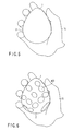
- FIG. 5 shows the state in which the operator grasps the outer shell 2 with a hand and fingers used as the object 15.
- a portion 400 in which the hand and fingers touch the outer shell 2 is distributed as shown in FIG. 6 and the pattern of the contact portion 400 is deformed when receiving external force by the hand and fingers.
- the degree of weight added to the outer shell 2 by an influence of the external force is calculated by adding constant weights to respective measurement points and substituting them into the correlation between the calibrated deformation amount and external force.
- the fisheye lens as the photographing optical system 4 (4a) performs photographing by f ⁇ lens, that is, equidistant projection when the deformation amount of the outer shell pattern 3 is calculated, an image of the outer shell pattern 3 is uniformly formed in comparison with photographing by a super wide-angle lens in which normal distortion is corrected since the outer shell 2 is a subject of substantially a spherical shell form. Therefore, a variation in the deformation amount at the measurement time can be made small and a variation in the force measurement can be reduced.
- each configuration of the embodiment of this invention can be variously modified and altered.
- the fisheye lens 4a is used for photographing on the upper portion of substantially the egg-shaped human interface equipment 1 and photographing is performed by the reflection mirror 4b from the side surface to the lower portion, but as shown in FIG. 7, both portions can be configured by fisheye lenses for photographing.
- the configuration is made to communicate with the host computer 11 by use of the communication device 10, but the host computer 11 can be contained, and in this case, the communication device 10 can be omitted.
- the devices such as the calibration device 12, pattern deformation recognition device 8 and force estimation device 9 can be provided in the host computer 11.
- the communication device 10 radio communication such as bluetooth or IEEE 802.11 wireless LAN or wired communication such as IEEE 1394, USB which can also be used as power supply can be used.
- a power supply to drive the various types of devices may be attained by containing a secondary battery such as a lithium ion battery charger in the human interface equipment 1, a solar battery or a pendulum generating device can be contained and a power supply can be charged by electromagnetic induction by providing an electromagnetic induction type charging coil.
- a secondary battery such as a lithium ion battery charger in the human interface equipment 1
- a solar battery or a pendulum generating device can be contained and a power supply can be charged by electromagnetic induction by providing an electromagnetic induction type charging coil.
- a deformation amount derived by calibration can be attained by looking up a table between the weight and deformation amount derived based on deformation simulation by strength of materials, FEM.
- an inner shell 17 which has a configuration harder than the outer shell 2, is configured by a transmission material and is placed with constant distance may be placed inside the outer shell 2.
- the inner shell 17 has a role of controlling a deformation amount of the outer shell 2 and can protect the illumination device 7 and photographing device 5 from excessive deformation of the outer shell 2.
- relatively soft resin such as silicone rubber, vinyl chloride or the like can be used for the outer shell 2 and relatively hard resin such as acryl, ABS resin, styrene resin or the like can be used for the inner shell 17.
- deformation of the outer shell 2 is measured by use of the outer shell pattern 3 provided on the outer shell 2, but the configuration can be made to measure deformation of the outer shell 2 by use of a slit, a trigonometrical survey by stripe projection and photographing, three-dimensional measurement by random dot pattern projection and stereo measurement or the like and estimate the pressure distribution or the position/pose of the hand and fingers.
- a deformation amount may be estimated by measuring blurring due to defocusing of the pattern by deformation.
- a human interface equipment 1 of the present embodiment includes an outer shell 2 which has a diffusion surface 18 on an outer shell exterior surface 2-2 and a transmission surface 19 on an outer shell interior surface 2-1 to permit light to pass therethrough, an illumination device 7 which illuminates the outer shell 2, photographing optical systems 4 which each guide an image of a neighborhood of the outer shell exterior surface 2-2 in a photographable fashion, photographing devices 5 for photographing, a contact surface detecting device (which will be described later) which detects touch of a hand and fingers closely adhered to the outer shell 2 as an image, and a force estimation device (which will be described later) which estimates force applied to the outer shell 2 based on an increase of decrease of the contact surface.
- the basic configuration of the second embodiment is common to the first embodiment, but they are different in an estimation method of force and to-be-photographed object.
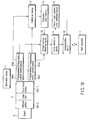
- FIG. 10 is a block diagram of the human interface equipment 1 of the present embodiment.
- a portion different from the block diagram of FIG. 4 which is the first embodiment is that the outer shell 2 has the diffusion surface 18 and transmission surface 19 and includes a contact surface detecting device 20 instead of the pattern deformation recognition device 8.
- the outer shell exterior surface 2-2 of the outer shell 2 of the present embodiment is configured to have the diffusion surface 18 which has fine concave and convex portions on the surface in a so-called frosted glass form. Therefore, an image of an object 15 has low contrast and set in a blurred state until it touches the surface. When the object 15 touches, the contrast is enhanced and a fine structure becomes visible. Particularly, when the object 15 is a hand and fingers, an image component such as fingerprints and wrinkles will be clearly photographed.
- a contact surface 401 is detected by the contact surface detecting device 20 by detecting a variation in the contrast based on an image photographed by the photographing device 5 via the photographing optical system 4.
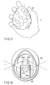
- FIG. 11 shows the distribution of the contact surface 401 of the hand and fingers.
- the hand/finger position/pose estimation device 16 acquires the distribution as an image and estimates the position/pose of the hand and fingers.
- the contact area gradually increases according to force applied by the hand and fingers. Since the skin of the surface of the hand and fingers also has resiliency, the weight applied to the outer shell 2 can be estimated based on the variation thereof.
- each configuration of the embodiment of this invention can be variously modified and changed.
- it is determined that the diffusion surface 18 is damaged and set into a transmission state and the area thereof may be omitted from a process of estimation of the hand/finger position/pose and force estimation.
- FIG. 12 is a view showing a modification of the configuration of the present embodiment.
- the diffusion surface 18 is provided on the outer shell 2, but as shown in the drawing, when the configuration is made to set the depth 500 of field of the photographing optical system 4 and photographing device 5 sufficiently small and set the focus on a nearer area from a neighborhood of the surface of the outer shell exterior surface 2-2 of the outer shell 2, the contact area can be detected even if the diffusion surface 18 is not provided. In this case, it is not necessary to consider the damage of the diffusion surface 18 of the surface.
- touch of the hand and fingers and pressure may be estimated by providing a liquid crystal heat sensitive layer used for a liquid crystal thermometer or a pressure sensitive layer (not shown) on the outer shell exterior surface 2-2 of the outer shell 2 and measuring change of color due to a temperature change caused by touch of the hand and fingers and change of color due to application of pressure by use of the photographing device 5.
- a liquid crystal heat sensitive layer used for a liquid crystal thermometer or a pressure sensitive layer (not shown) on the outer shell exterior surface 2-2 of the outer shell 2 and measuring change of color due to a temperature change caused by touch of the hand and fingers and change of color due to application of pressure by use of the photographing device 5.
- the configuration can be made to generate a command by measuring the transition state of a contact area in addition to the first embodiment.
- the present embodiment has a feature that a venous pattern of a hand and fingers can be photographed in addition to the second embodiment. Therefore, in this case, in addition to the configuration of the second embodiment, a visible light cutting and infrared transmission filter 21 is provided on an outer shell 2 and the illumination device 7 is replaced by an infrared illumination device 22. Further, a venous pattern collating device 23 is newly added and is connected to a hand/finger position/pose estimation device 16 and contact surface detecting device 20.
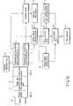
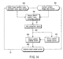
- FIG. 14 is a diagram showing the configuration of the venous pattern collating device 23 which includes a vein recognition device 26, venous pattern storage section 601, contact surface image input section 602, hand/finger position/pose estimated value input section 603, venous pattern position/pose correcting section 604, venous pattern collating section 605 and collation result output section 606.
- a contact surface is detected like the second embodiment.
- an infrared image is used, but since the operation of the hand/finger position/pose estimation device 16 and contact surface detecting device 20 is basically the same as in the second embodiment, the detail explanation thereof is omitted here.
- a venous pattern 600 in the hand and fingers is also photographed at the same time by photographing with an infrared image.
- the position/pose of the hand and fingers is estimated by the hands position/pose estimation device 16.
- An image of the hand and fingers of the photographed contact surface is input from the contact surface image input section 602. Further, an estimated value of the position/pose of the hand and fingers is input from the hand/finger position/pose estimated value input section 603.
- the venous pattern position/pose correcting section 604 normalizes the venous pattern 600 by correcting an image which is modified according to the position/pose and shape of the hand and fingers and captured, corrects the same into an image which coincides with the registered venous pattern and outputs it.
- the vein recognition device 26 estimates a position of the hand and fingers which corresponds to a portion of the contact surface 401.
- the venous pattern collating section 605 collates the venous pattern which coincides with each contact portion read out from the venous pattern storage section 601 with the venous pattern 600 from the vein recognition device 26. The result of collation is output from the collation result output section 606.
- the vein can also be recognized in a desired grasping manner, individual authentication can be made in a natural form and a function as the human interface equipment can also be realized with a simple configuration.
- each configuration of the embodiment of this invention can be variously modified and altered.
- the venous pattern collating device 23 can be omitted and if the configuration in which the outer shell 2 and illumination device 7 of the second embodiment are modified is made, the internal structure cannot be observed by use of visible light and the exterior design can be changed.
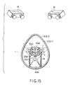
- the human interface equipment of the present embodiment has no diffusion surface and utilizes a method for detecting a contact surface based on the depth of field. Further, it has a single or a plurality of stereo cameras 24 which monitor the infrared illumination device 22 emitting infrared light used in the third embodiment from the exterior. A light emission spot array of the infrared illumination device 22 which is geometrically known and a light emission patter thereof are controlled by an illumination pattern control device 25.
- An ID recognition device 37 of individual points is connected to the stereo cameras 24 and a three-dimensional position/pose measuring device 27 derives the position and pose of the human interface equipment based on the ID recognition result in the ID recognition device 37.
- the derivation result is input to a host computer 11.
- the three-dimensional position/pose of the human interface equipment 1 can be measured if the infrared illumination device 22 of at least three points is captured by the stereo cameras 24.
- each configuration of the embodiment of this invention can be variously modified and altered.
- the same effect can be attained by performing the operation by use of visible light.
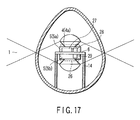
- FIG. 17 is a view showing a modification of the present embodiment.
- the three-dimensional position/pose is derived by containing a three-dimensional position/pose measuring device 27 which is configured by a gyro sensor 28, acceleration sensor 29 and the like in the human interface equipment 1.
- a gyro sensor 28 and acceleration sensor 29 it is desirable to place and position the gyro sensor 28 and acceleration sensor 29 in a blind spot of a photographing optical system 4.
- a level may be placed in a visible range of the camera as a sensor which measures the position/pose and the pose of the human interface equipment 1 in the gravitational direction may be measured by photographing a bubble position thereof.
- the field of view can be effectively utilized by forming an opening in an optical axis (an area reflected and photographed by the photographing device 5 itself) of the reflection mirror and placing the level in the portion thereof.
- the configuration may be made to detect the pose by inserting a small amount of beads, iron spheres or colored liquid between the inner shell and the outer shell and observing the movement thereof in the gravitational direction by use of the photographing device 5.
- a light emission pattern may be used as an infrared communication protocol of IrDA or the like and may be used for transmission of measurement values of the hand/finger pose and the pressure distribution value of the human interface 1.
- the configuration can be made to control household equipments or the like by a command based on tactile sensing by setting the same in conformity to a command of an infrared remote controller.
- electrodes, electromyography sensor, temperature sensor or the like for measurement of a physiological amount for example, for measurement of body fat may be provided on the exterior surface of the outer shell 2 in the case of the first embodiment, the configuration can be made to estimate the pulsation of a corresponding portion by extracting the portion corresponding to a vein of part of the image, tracking and correcting the position thereof in the case of the second and third embodiments, and thus the configuration may be made to simultaneously acquire various physiological amounts.
- a command generation device 30 is provided to generate and store a command.
- the configuration can be commonly applied to the first, second, third, fourth embodiments.
- the command generation device 30 is arranged between a force estimation device 9 and a communication device 10 and connected to a three-dimensional position/pose measuring device 27 and hand/finger position/pose estimation device 16.
- FIG. 19 shows the configuration of the command generation device 30 which includes a hand/finger pose input section 31, pressure distribution input section 32, three-dimensional position/pose input section 33, command recognizing section 34, command storage section 35 and command output section 36.
- Hand/finger pose data 701 input from the hand/finger pose input section 31 pressure distribution data 702 input from the pressure distribution input section 32 and three-dimensional position/pose data 703 input from the three-dimensional position/pose input section 33 are input to the command recognizing section 34.
- the command recognizing section 34 compares the input data items 701, 702, 703 with a command previously set in the command storage section 35, derives a threshold based on the total sum of the whole pressures and generates a command by use of a variation in the pressure distribution of each finger based on the above result.
- a case wherein a command of a mouse widely used in computers is generated is considered.
- the pressure value of the index finger is recognized based on the hand/finger position/pose data, normal grasping is recognized when the pressure value is not larger than the threshold, a command corresponding to left click of a mouse is recognized when the pressure value exceeds the threshold, for example, and the command is output.
- a command corresponding to a right click of the mouse is assigned to the middle finger.
- the pointer movement amount of the mouse is set large, and when it is lightly grasped, the movement amount is set small.
- the present human interface equipment 1 is used for measurement of the degree of tension.
- the gripping force of a human is generally set in a weak state and the operation of lightly grasping an object so as not to drop the same is performed.
- the degree of tension can be measured and it can be acquired as command data 704 of the degree of tension by measuring the pressure value based on the pressure distribution data 702 of the present human interface equipment 1.
- command data 704 corresponding to the degree of reliability with respect to the human interface equipment 1 based on the hand/finger pose data and pressure distribution data by applying the same to a model in which the degree of reliability with respect to the present human interface equipment 1 is low when the operation of pinching the present human interface equipment 1 is performed so as to lightly grasp the same and the degree of reliability is high when it is grasped so as to be covered with the whole portion of the palm.
- command data 704 indicating that there is a will of protection may be output
- command data 704 indicating that the human interface equipment 1 is regarded as an object to be dependent on may be output.
- the degree of tension of the movement can be measured based on the pressure distribution data and three-dimensional position/pose data of the present interface. For example, at the time of smooth movement of the low degree of tension when he has the present human interface equipment 1 and performs an aerobic dance, command data 704 indicating that a variation in the three-dimensional position/pose is less subject to a smooth and fine positional variation, it can be recognized as a relaxed state based on the pressure distribution data 702 or the like and relaxed exercise is taken is output.
- command data 704 indicating a warning that the force is applied, for example, unreasonable force is applied and dangerous exercise which causes injury is performed is output.
- two human interface equipments 1 can be held in two hands.
- command generation device 30 for command generation may be contained in the human interface equipment 1 as in the present embodiment or may be realized as a program in the host computer 11.
- the configuration may be made to detect pressure distribution by arranging pressure sensors, for example, FSR sensors (made by Interlink Electronics Co.) or the like using conductive rubber in a matrix form between the inner shell and the outer shell. Further, part of the pressure sensors may be partially arranged for pressure detection of substantially the egg-shaped top portion and bottom surface in which the outer shell is difficult to be deformed and the value thereof may be used in a complementary fashion. In this case, an output of the pressure sensor is used for recognition of the hand/finger position/pose as a value of the pressure distribution.
- FSR sensors made by Interlink Electronics Co.
- calibration for a threshold value of pressure can be performed by use of the individual authentication result by use of a vein or generation of command data 704 relating to a plurality of persons may be customized.
- the size of the human interface equipment 1 is constant, but the size of the hand and fingers of the operator is different between individuals. Customization can be attained by taking the difference between individuals into consideration and storing a variation in the pressure distribution at the time of command generation in the command storage section 35.
- a configuration can be made to enhance the probability of recognition based on the input history of discriminated commands according to the individual authentication result by use of a vein or the like or adaptively learn a variation in the command input of the operator with time (for example, a variation in the exercise ability or growth of a child).
- the human interface equipment 1 which can more highly estimate even emotion of the operator can be simply attained.
- the embodiment relating to this invention corresponds to the first and second embodiments.
- the photographing optical system corresponds to a fisheye lens or hyperboloid mirror, but two optical systems may be configured by the same type and a conical surface or paraboloid, free curved surface or the like can be contained instead of the hyperboloid.
- a variation of a subject is input by recognizing a variation in an image photographed by the outer shell and the photographing device having the photographing optical system contained therein by use of the variation recognition device.
- a hand and fingers which grasp the human interface or the interior surface of the outer shell can be photographed without being shielded by a shielding member and input of gesture by the way of grasping by the hand and fingers can be effectively recognized. Further, since a movable portion such as a bending sensor is not provided, the characteristic that a fault is difficult to occur is provided.
- the depth of field is set near the outer shell.
- recognition of a variation of the subject can be limited to a neighborhood of the outer shell and can be more simply performed.
- the embodiment relating to this invention corresponds to the first embodiment.
- a pattern formed on the outer shell is photographed by the photographing device via the photographing optical system and deformation of the outer shell is derived by the deformation recognition device based on the image.
- a human interface equipment which can detect a contact state of substantially the whole surface of the outer shell based on a deformation amount by using a plurality of photographing devices can be obtained.
- a pattern drawn on the interior surface of the outer shell is photographed by the photographing device.
- the embodiment relating to this invention corresponds to the first embodiment.
- the photographing optical system in the configuration corresponds to a fisheye lens or hyperboloid mirror, but two optical systems may be configured by the same type and a conical surface or paraboloid, free curved surface or the like can be contained instead of the hyperboloid. Further, the force also contains pressure.
- a pattern formed on the outer shell is photographed by the photographing device via the photographing optical system and deformation of the outer shell is derived by the deformation recognition device based on the image and force distribution is derived based on the deformation amount by the force estimation device.
- a human interface equipment which can detect the contact weight of substantially the whole surface of the outer shell and the distribution thereof by using a plurality of photographing devices can be obtained.
- the interior surface of the outer shell is photographed by the fisheye lens.
- a pattern of the outer shell is photographed as a panoramic circumferential image by a hyperboloid full-circumference mirror.
- a pattern distorted by deformation of the outer shell is photographed and thus the shape of the hand and fingers is estimated based on force distribution estimated by force estimation means.
- the position of the hand and fingers which grasp the human interface equipment can be estimated.
- the inner shell stops excessive deformation of the outer shell.
- the photographing device, illumination device and the like are protected by the inner shell. Further, since the inner shell is formed of the transmission material, photographing is not obstructed.
- the embodiment relating to this invention corresponds to the second embodiment.
- the photographing optical system in the configuration corresponds to a fisheye lens or hyperboloid mirror, but two optical systems may be configured by the same type and a conical surface or paraboloid, free curved surface or the like can be contained instead of the hyperboloid.
- the outer shell having an exterior surface of a diffusion surface and an interior surface of a transmission surface is illuminated by the illumination device, a neighborhood of the outer wall surface is photographed by the photographing optical system, a subject such as the hand and fingers which touch the outer wall surface is photographed by the photographing device, an area of the hand and fingers closely adhered is detected by the contact surface detecting device, and force applied to the outer shell is estimated by the force estimation device based on an increase or decrease in the contact surface.
- Force can be estimated by use of resiliency of the hand and fingers by detecting an area in which the hand and fingers touch the exterior surface of the outer shell by an image of the hand and fingers and the like pressed against the diffusion surface and an image of the hand shape can be simultaneously photographed.
- the exterior surface of the outer shell is formed into a diffusion surface such as frosted glass, a variation in the image of the hand/finger portion closely adhered to the diffusion surface is input to the contact surface detecting device to recognize a contact surface and force applied to the outer shell is estimated by the force estimation device.
- a diffusion surface such as frosted glass
- the contact surface of the hand and fingers can be easily detected by emphasizing a closely adhered surface of the hand and fingers and the like by the diffusion surface and detecting the corresponding portion by the contact surface detecting device.
- the exterior surface of the outer shell is photographed by the fisheye lens.
- the exterior surface of the outer shell is photographed as a panoramic circumferential image by a hyperboloid full-circumference mirror.
- the position, pose and the like of the hand and fingers are estimated based on a touched portion and photographed hand/finger image.
- the way of grasping the human interface equipment can be measured.
- the embodiment relating to this invention corresponds to the third embodiment.
- the illumination device which illuminates the outer shell emits infrared rays to illuminate the contact surface of the hand and fingers and prevent visible light from being passed by the visible light cut filter of the outer shell.
- the hand/finger position/pose and pressure can be measured as if it does not look that visible light is emitted. Further, the internal structure can be shielded.
- the embodiment relating to this invention corresponds to the first, second embodiments.
- a command is generated based on deformation, force distribution.
- An input corresponding to sensitivity or input of non-language can be provided by generating a command according to the way of grasping the human interface equipment or the way of applying force.
- the embodiment relating to this invention corresponds to the first, second embodiments.
- a command is registered, learned based on deformation, force distribution.
- An input corresponding to sensitivity corresponding to the individual or input of non-language can be provided by registering or learning a command according to the way of grasping the human interface equipment or the way of applying force.
- the embodiment relating to this invention corresponds to the fourth, fifth embodiments.
- the position/pose of the human interface itself is input in addition to the pressure distribution, position/pose of the hand and fingers.
- a variation in the position/pose can be input at the same time as the pressure distribution, position/pose of the hand and fingers.
- the embodiment relating to this invention corresponds to the third, fifth embodiments.
- Venous pattern photographing by infrared photographing is acquired by the photographing device via the photographing optical system, a venous pattern is detected by the venous pattern detecting section, a venous pattern normalized by the venous pattern correcting section which corrects distorted venous pattern data based on the estimation result of the hand/finger pose is acquired and this is collated with a previously registered venous pattern in the venous pattern collating section.
- the measurement which grasps calibration data, habit and the like of the operator can be made by performing collation and a human interface equipment suitable to the individual can be provided.
- a human interface equipment which can recognize a variation in an image without being shielded by a shielding member by use of a small number of sensors.
- a human interface equipment which can attain authentication and interface by the same device is provided.
Landscapes
- Engineering & Computer Science (AREA)
- General Engineering & Computer Science (AREA)
- Theoretical Computer Science (AREA)
- Human Computer Interaction (AREA)
- Physics & Mathematics (AREA)
- General Physics & Mathematics (AREA)
- Multimedia (AREA)
- User Interface Of Digital Computer (AREA)
- Image Input (AREA)
- Measurement Of The Respiration, Hearing Ability, Form, And Blood Characteristics Of Living Organisms (AREA)
Applications Claiming Priority (2)
| Application Number | Priority Date | Filing Date | Title |
|---|---|---|---|
| JP2003403626A JP4169688B2 (ja) | 2003-12-02 | 2003-12-02 | ヒューマンインタフェース装置 |
| PCT/JP2004/017457 WO2005055029A1 (fr) | 2003-12-02 | 2004-11-25 | Dispositif d'interface humain et systeme d'interface humain |
Publications (1)
| Publication Number | Publication Date |
|---|---|
| EP1698962A2 true EP1698962A2 (fr) | 2006-09-06 |
Family
ID=34650076
Family Applications (1)
| Application Number | Title | Priority Date | Filing Date |
|---|---|---|---|
| EP04819776A Withdrawn EP1698962A2 (fr) | 2003-12-02 | 2004-11-25 | Dispositif d'interface humain et systeme d'interface humain |
Country Status (4)
| Country | Link |
|---|---|
| US (1) | US20060268109A1 (fr) |
| EP (1) | EP1698962A2 (fr) |
| JP (1) | JP4169688B2 (fr) |
| WO (1) | WO2005055029A1 (fr) |
Families Citing this family (24)
| Publication number | Priority date | Publication date | Assignee | Title |
|---|---|---|---|---|
| JP4635788B2 (ja) * | 2005-09-06 | 2011-02-23 | 株式会社日立製作所 | 弾力性素材を用いた入力装置 |
| JP4736052B2 (ja) * | 2006-07-21 | 2011-07-27 | ブラザー工業株式会社 | 操作信号出力装置及び操作システム |
| WO2008010581A1 (fr) * | 2006-07-21 | 2008-01-24 | Brother Kogyo Kabushiki Kaisha | Dispositif opérationnel et système opérationnel |
| JP4899806B2 (ja) * | 2006-11-08 | 2012-03-21 | トヨタ自動車株式会社 | 情報入力装置 |
| US20080232790A1 (en) * | 2007-03-23 | 2008-09-25 | David Lai | Camera monitor |
| JP4877015B2 (ja) * | 2007-03-30 | 2012-02-15 | 沖電気工業株式会社 | 静脈認証装置 |
| JP4916994B2 (ja) * | 2007-10-02 | 2012-04-18 | アルプス電気株式会社 | 中空型スイッチ装置及びこれを備えた電子機器 |
| JP5130885B2 (ja) | 2007-12-03 | 2013-01-30 | ソニー株式会社 | 情報処理装置、情報処理方法およびプログラム |
| JP2009267643A (ja) * | 2008-04-23 | 2009-11-12 | Smk Corp | リモートコントロール送信機 |
| JP5252579B2 (ja) * | 2009-03-02 | 2013-07-31 | Kddi株式会社 | 情報端末装置 |
| JP5455514B2 (ja) * | 2009-09-09 | 2014-03-26 | キヤノン株式会社 | 電子機器及びその制御方法 |
| JP5448752B2 (ja) * | 2009-11-27 | 2014-03-19 | 東海ゴム工業株式会社 | 入力インターフェイス装置 |
| JP5854685B2 (ja) * | 2011-07-29 | 2016-02-09 | キヤノン株式会社 | 眼科装置 |
| US8380995B1 (en) * | 2011-11-29 | 2013-02-19 | Google Inc. | Process for login of a computing device with a touchscreen |
| JP2015089383A (ja) * | 2013-11-05 | 2015-05-11 | セイコーエプソン株式会社 | 超音波プローブおよび超音波計測装置 |
| JP5921047B2 (ja) * | 2014-06-23 | 2016-05-24 | レノボ・イノベーションズ・リミテッド(香港) | ユーザーインターフェース装置 |
| EP3176681A4 (fr) | 2014-07-30 | 2018-04-18 | Sony Corporation | Dispositif, procédé et programme de traitement d'informations |
| US9684227B1 (en) * | 2015-04-20 | 2017-06-20 | Hoyos Vsn Corp. | Protective container for a 360 degree camera and method of forming same |
| CN109074153A (zh) * | 2016-03-29 | 2018-12-21 | 斋藤创造研究所株式会社 | 一种输入装置及图像显示系统 |
| JP6723631B2 (ja) * | 2016-09-16 | 2020-07-15 | アルプスアルパイン株式会社 | 操作装置 |
| KR102019795B1 (ko) * | 2017-10-12 | 2019-09-20 | 한국생산기술연구원 | 구 형상의 3차원 동작 입력 장치 및 이를 이용한 3차원 동작 입력 방법 |
| KR102019793B1 (ko) * | 2017-10-12 | 2019-09-20 | 한국생산기술연구원 | 신축성 소재를 이용한 3차원 동작 입력 장치 및 이를 이용한 3차원 동작 입력 방법 |
| JP7093075B2 (ja) * | 2018-04-09 | 2022-06-29 | 東芝エネルギーシステムズ株式会社 | 医用画像処理装置、医用画像処理方法、およびプログラム |
| JP7110314B2 (ja) * | 2020-12-18 | 2022-08-01 | ヤフー株式会社 | 情報処理装置、情報処理方法、及び情報処理プログラム |
Family Cites Families (12)
| Publication number | Priority date | Publication date | Assignee | Title |
|---|---|---|---|---|
| US4641350A (en) * | 1984-05-17 | 1987-02-03 | Bunn Robert F | Fingerprint identification system |
| US5483261A (en) * | 1992-02-14 | 1996-01-09 | Itu Research, Inc. | Graphical input controller and method with rear screen image detection |
| JPH0619618A (ja) * | 1992-06-30 | 1994-01-28 | Sony Corp | 入力装置 |
| US5982352A (en) * | 1992-09-18 | 1999-11-09 | Pryor; Timothy R. | Method for providing human input to a computer |
| JPH07182101A (ja) * | 1993-10-26 | 1995-07-21 | Itu Res Inc | グラフィック入力装置および方法、グラフィックオブジェクト操作方法、グラフィック入力信号供給方法 |
| US5757360A (en) * | 1995-05-03 | 1998-05-26 | Mitsubishi Electric Information Technology Center America, Inc. | Hand held computer control device |
| US5801681A (en) * | 1996-06-24 | 1998-09-01 | Sayag; Michel | Method and apparatus for generating a control signal |
| US6950539B2 (en) * | 1998-09-16 | 2005-09-27 | Digital Persona | Configurable multi-function touchpad device |
| US6552713B1 (en) * | 1999-12-16 | 2003-04-22 | Hewlett-Packard Company | Optical pointing device |
| US7859519B2 (en) * | 2000-05-01 | 2010-12-28 | Tulbert David J | Human-machine interface |
| DE10100617A1 (de) * | 2001-01-09 | 2002-07-18 | Siemens Ag | Steuerbare Anordnung mit Benutzerauthentisierung |
| JP2002359872A (ja) * | 2001-05-31 | 2002-12-13 | Sony Corp | 携帯無線端末装置 |
-
2003
- 2003-12-02 JP JP2003403626A patent/JP4169688B2/ja not_active Expired - Fee Related
-
2004
- 2004-11-25 EP EP04819776A patent/EP1698962A2/fr not_active Withdrawn
- 2004-11-25 WO PCT/JP2004/017457 patent/WO2005055029A1/fr not_active Ceased
-
2006
- 2006-06-01 US US11/445,439 patent/US20060268109A1/en not_active Abandoned
Non-Patent Citations (1)
| Title |
|---|
| See references of WO2005055029A1 * |
Also Published As
| Publication number | Publication date |
|---|---|
| JP4169688B2 (ja) | 2008-10-22 |
| US20060268109A1 (en) | 2006-11-30 |
| JP2005165670A (ja) | 2005-06-23 |
| WO2005055029A1 (fr) | 2005-06-16 |
Similar Documents
| Publication | Publication Date | Title |
|---|---|---|
| EP1698962A2 (fr) | Dispositif d'interface humain et systeme d'interface humain | |
| Kudrinko et al. | Wearable sensor-based sign language recognition: A comprehensive review | |
| JP7210204B2 (ja) | 変化する接触感度を有する接触及び形状センサに対応したロボット、及び、ロボットを提供するための方法 | |
| EP3652619B1 (fr) | Dispositif de commande électronique avec détection de mouvement de doigt | |
| CN105824431B (zh) | 信息输入装置与方法 | |
| US10209881B2 (en) | Extending the free fingers typing technology and introducing the finger taps language technology | |
| Shukor et al. | A new data glove approach for Malaysian sign language detection | |
| Kim et al. | The gesture watch: A wireless contact-free gesture based wrist interface | |
| EP1810217B1 (fr) | Reconnaissance de gestes automatisee | |
| CN112926423A (zh) | 捏合手势检测识别方法、装置及系统 | |
| CN104254816B (zh) | 数据输入装置 | |
| US20030048260A1 (en) | System and method for selecting actions based on the identification of user's fingers | |
| US20220155866A1 (en) | Ring device having an antenna, a touch pad, and/or a charging pad to control a computing device based on user motions | |
| US20180158370A1 (en) | Hand motion interpretation and communication apparatus | |
| WO2010032223A1 (fr) | Dispositif porté au doigt et procédés d’interaction et procédés de communications | |
| CN114008571B (zh) | 利用手持式控制器的系统和方法 | |
| Nanayakkara et al. | EyeRing: a finger-worn assistant | |
| CN113557069B (zh) | 用于手势分类和施加的力估计的无监督机器学习的方法和装置 | |
| TW201633067A (zh) | 檢測裝置、電子機器、檢測方法及程式 | |
| JP7260697B2 (ja) | 物体に接触して姿勢及び力を検出するための変形可能なセンサ及び方法 | |
| US20070124703A1 (en) | Command input method using motion recognition device | |
| WO2021207033A1 (fr) | Dispositif d'entrée pour commander un dispositif informatique avec un pavé tactile ayant une surface incurvée configurée pour détecter une entrée tactile | |
| Wang et al. | Continuous hand gestures detection and recognition in emergency human-robot interaction based on the inertial measurement unit | |
| KR101396488B1 (ko) | 신호 입력 장치 및 신호 입력 방법 | |
| Wilson | Sensor-and recognition-based input for interaction |
Legal Events
| Date | Code | Title | Description |
|---|---|---|---|
| PUAI | Public reference made under article 153(3) epc to a published international application that has entered the european phase |
Free format text: ORIGINAL CODE: 0009012 |
|
| 17P | Request for examination filed |
Effective date: 20060622 |
|
| AK | Designated contracting states |
Kind code of ref document: A2 Designated state(s): DE FR GB |
|
| DAX | Request for extension of the european patent (deleted) | ||
| RBV | Designated contracting states (corrected) |
Designated state(s): DE FR GB |
|
| STAA | Information on the status of an ep patent application or granted ep patent |
Free format text: STATUS: THE APPLICATION HAS BEEN WITHDRAWN |
|
| 18W | Application withdrawn |
Effective date: 20090915 |