EP1699122A2 - Gehäuse für eine Kabelverbindung - Google Patents
Gehäuse für eine Kabelverbindung Download PDFInfo
- Publication number
- EP1699122A2 EP1699122A2 EP06003181A EP06003181A EP1699122A2 EP 1699122 A2 EP1699122 A2 EP 1699122A2 EP 06003181 A EP06003181 A EP 06003181A EP 06003181 A EP06003181 A EP 06003181A EP 1699122 A2 EP1699122 A2 EP 1699122A2
- Authority
- EP
- European Patent Office
- Prior art keywords
- housing
- opening
- plate
- cable
- blocking plate
- Prior art date
- Legal status (The legal status is an assumption and is not a legal conclusion. Google has not performed a legal analysis and makes no representation as to the accuracy of the status listed.)
- Withdrawn
Links
- 230000000903 blocking effect Effects 0.000 claims abstract description 38
- 230000000295 complement effect Effects 0.000 claims description 6
- 238000007789 sealing Methods 0.000 description 20
- 238000009413 insulation Methods 0.000 description 4
- 238000004519 manufacturing process Methods 0.000 description 4
- 230000006378 damage Effects 0.000 description 3
- 208000027418 Wounds and injury Diseases 0.000 description 2
- 150000001875 compounds Chemical class 0.000 description 2
- 208000014674 injury Diseases 0.000 description 2
- 238000002955 isolation Methods 0.000 description 2
- 230000035515 penetration Effects 0.000 description 2
- 230000006835 compression Effects 0.000 description 1
- 238000007906 compression Methods 0.000 description 1
- 230000001419 dependent effect Effects 0.000 description 1
- 239000000834 fixative Substances 0.000 description 1
- 239000000463 material Substances 0.000 description 1
- 210000002445 nipple Anatomy 0.000 description 1
- 230000003287 optical effect Effects 0.000 description 1
- 230000000717 retained effect Effects 0.000 description 1
Images



Classifications
-
- H—ELECTRICITY
- H02—GENERATION; CONVERSION OR DISTRIBUTION OF ELECTRIC POWER
- H02G—INSTALLATION OF ELECTRIC CABLES OR LINES, OR OF COMBINED OPTICAL AND ELECTRIC CABLES OR LINES
- H02G15/00—Cable fittings
- H02G15/013—Sealing means for cable inlets
Definitions
- the invention relates to a housing for a cable connection with at least one housing opening for carrying one or more single or multi - core cables, in particular low - voltage cables, and a space for accommodating the cable connection, which can be filled with an insulating gel.
- Housing of the type described above are manufactured and sold by the applicant.
- the function of these enclosures is primarily to protect cable connector blocks located in the housings.
- these housings are filled with an insulating gel to insulate the cable connector blocks disposed therein from moisture.
- housing have been laid underground, so that for a sufficient mechanical protection, at least in the region of the housing opening comparatively thin housing walls were sufficient.
- the strength of these housing walls in the region of the housing opening or its strength is dimensioned such that these walls retain the insulating gel filled in the housing.
- a housing for a cable splice connection which has a radially deformable by pressure sealing element, wherein the sealing compound of the sealing element is a suitable insulation gel.
- the sealing element is inserted into the base of a dome-shaped housing body and has openings for the passage of several cables.
- the cables are slidably guided in the sealing element.
- the invention has for its object to improve a housing for a cable connection of the type mentioned in such a way that the housing provides protection against manual force from the outside in the region of the housing opening, so that the housing can be installed above ground. Moreover, the housing should be able to be manufactured easily and with relatively low manufacturing costs.
- the invention is based on the idea to provide a blocking plate for closing the housing opening, wherein the blocking plate is firmly connectable to the housing in the region of the housing opening and has at least one plate opening for cable feedthrough.
- This locking plate has the advantage that the housing opening can be closed by a robust component, so that penetration into the housing interior with pointed objects, such as wires or the like is effectively prevented.
- the housing can also be used above ground without fear of children damaging the housing and injuring itself.
- the lock plate can be made separately from the housing and used when laying on site.
- the blocking plate can thus have a simple geometry, so that the production costs are not significantly increased with a simultaneous improvement of the contact protection.
- a cable holder in particular a cable clamp can be inserted into the plate opening.
- This cable holder serves as a strain relief, possibly occurring tensile forces are introduced via the locking plate firmly connected to the housing in this.
- a flexible grommet can be inserted into the plate opening which isolates the cables only against moisture but does not provide strain relief. This embodiment is associated with even lower production costs.
- the outer circumference of the blocking plate is substantially adapted to the inner contour of the housing in the region of the housing opening. This ensures that the blocking plate covers the entire cross-sectional area of the housing in the region of the housing opening and thus completely closes.
- At least one projection can be provided on the outer circumference of the blocking plate, which can be brought into engagement with a complementarily formed recess in the housing.
- the locking plate is easily connected to the housing and stored axially.
- two oppositely disposed edges of the locking plate can engage in two complementary recesses formed in the housing in use, whereby an even better fixation of the locking plate is achieved in the housing.
- the thickness of the blocking plate may be such that it withstands a pressure of at least 10 N / mm 2 .
- a housing provided with such a blocking plate meets the requirements of the protection classification IP 67.
- FIG. 1 shows an embodiment of a housing 10 according to the invention is shown with its main components, as it mainly for the protection of cable connections, in particular cable splices is used.
- This housing can be installed above ground as well as underground.
- the housing 10 suitable for receiving in-line splice connections comprises two housing openings 11 which are provided at two axial ends of the mainly longitudinally extending housing 10.
- the invention also includes housing for butt splices in which only one housing opening is provided through which all incoming and outgoing cables are routed. The other end of the housing would then be designed as a blind end.
- a space 12 is provided in the housing (see Fig. 2), in which the cable connection, in particular a cable connector block is arranged, which connects and fixes the cable ends or the wire ends of the individual cables.
- the cable connection in particular a cable connector block
- this is longitudinally divided and provided with a hinge 23.
- the hinge 23 may be integrally formed with the housing 10, for example as a hinge band.
- latching lugs 24 In the closed state of the housing 10, this is locked by latching lugs 24 which are arranged on a housing part of the longitudinally split housing 10.
- the locking lugs 24 engage behind a laterally attached to the other housing part, in the longitudinal direction extending bar 25, so that the housing is fixed in the closed state.
- the locking lugs 24 and the bar 25 are released.
- the housing is closed or closable in the region of the housing opening 11 by a blocking plate 13 according to FIGS. 4 to 7.
- the position of the locking plate 13 is shown in Figures 1 and 2.
- the position of the blocking plate 13 shown in the figures is to be understood as an example.
- the blocking plate 13 can be arranged further inside the housing or closer to the edge of the housing be. In extreme cases, the blocking plate 13 can be flush with the edge of the housing.
- projections 19 are provided, which are particularly well visible in Figures 2 and 4 to 7.
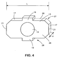
- the projections 19, in the present case two projections 19, are formed on the outer periphery 17 of the locking plate 13 and project beyond side surfaces 28 which extend perpendicular to the front 26 and back 27 of the locking plate 13 and connect them.
- the two projections 19 are arranged centrally and symmetrically in the longitudinal direction L of the blocking plate 13. As shown in Figures 4 to 7, the two projections 19 are provided on opposite sides or side surfaces 28 of the locking plate 13.
- recesses 20 are provided in the housing 10 in the region of the housing opening, which recesses 20 are designed to be complementary to the two projections 19.
- the recesses 20 are shown in Figures 1, 2 and 3. When the housing 10 is closed, the two projections 19 are in engagement with the complementary formed recesses 20, whereby the locking plate 13 is fixed in the housing 10.
- a further fixation of the locking plate 13 in the housing 10 is effected in that two oppositely disposed edges 21 of the locking plate 13 engage in two further complementarily formed recesses 22 in the housing 10.
- the two edges 21 limit the blocking plate in its longitudinal extent.
- the longitudinal dimensions of the blocking plate 13, specifically in the direction of the double arrow L shown in FIG. 4, are dimensioned such that the length L of the blocking plate is slightly larger than the inner contour or the (inner) inner walls of the housing 10, so that the two Edges 21 of the locking plate 13 protrude into the two correspondingly formed recesses 22 in the housing.
- the two recesses 22 are shown in Figures 1 and 2. From this arrangement it follows that the blocking plate 13 is held both by the two projections 19, as well as by the two edges 21 in the housing 10. Since the two projections 19 and the two edges 21 are each formed on different opposite sides of the locking plate 13, the locking plate 13 is mounted in the assembled state on all sides in the housing 10.
- the recesses 20, 22 of the housing 10 in the region of the housing opening 11 shown in FIG. 1 are evenly distributed over the circumference of the housing 10.
- the two provided for the projections 19 recesses 20 on the upper side 29 and the bottom 30 and the two provided for the edges 21 recesses 22 on the two side surfaces 31 of the housing 10 are arranged.
- top 29 and bottom 30 of the housing 10 relate only to the view shown in Figure 1 of the housing 10. In use, of course, other housing surfaces can be arranged above or below.
- fixative d. H. the projections 19 or the edges 21 and the corresponding recesses 20, 22 is possible.
- the shape and number of fixing means, in particular the projections 19 may vary. For example, 3, 4 or more protrusions or other fixing means may be provided.
- Complete coverage of the housing opening 10 is achieved, in particular, by virtue of the fact that the outer circumference of the blocking plate 13 is essentially adapted to the inner contour 18 of the housing 10 in the region of the housing opening 11.
- the locking plate 13 thus covers the cross section of the housing opening 11 and thus effectively prevents penetration of sharp objects into the housing interior.
- the shape of the lock plate 13 may vary depending on the shape of the housing opening 11.
- the longitudinal extent L of the locking plate 13 can be reduced so that the two edges 21 are arranged closer to each other, as shown in Figures 5, 6.
- the distance between the two edges 21 is slightly larger than the corresponding, (in the view of Figures 1 to 3 lateral) inner walls of the housing 10, so that the two edges 21 of the locking plate 13 in the can complementarily formed recesses 22 in the housing 10 engage.
- the blocking plate may also be circular or elliptical, wherein in the case of the circular locking plate a plurality of projections distributed over the circumference and are provided radially outwardly extending.
- the length of the major axis of the elliptical locking plate may be slightly larger than the inner wall of the housing, so that the two ends of the locking plate engage in the longitudinal direction in the housing formed corresponding recesses.
- the feature according to which the outer circumference 17 of the blocking plate 13 is substantially adapted to the inner contour 18 of the housing 10 in the region of the housing opening 11 does not exclude certain areas of the blocking plate 13, such as the projections 19 and the edges 21, via the inner contour 18 of the housing 10 protrude to fulfill a fixing function.
- the locking plate 13 has a plate opening 14, which serves for cable passage.
- the plate opening 14 is arranged centrally in the blocking plate 13 in this example.
- the plate opening 14 may also be provided at other locations in the locking plate 13.
- more than one plate opening 14 may be provided when multiple cables are to be passed through a housing opening 11 in the housing 10, as is the case for example with butt splices.
- a cable holder 15 in particular a cable clamp with a rotary closure, as shown in Figure 1, are used.
- a cable holder 15 conventional rotary fasteners may be used, which have a threaded clamping body 15 a, which is screwed by two nuts on the front 26 and the back 27 with the locking plate 13.
- a union nut 15b By a union nut 15b a guided through the cable holder 15 cable (not shown) sealingly clamped, so that the cable holder 15 acts both as a strain relief, as well as insulation.
- the housing 10 may be equipped on both sides with the cable holder 15 and with the nozzle 16.
- the spout 16 is frusto-conical and has a plurality of concentrically arranged, offset portions 16a with different diameters. By cutting the grommet 16 to the stepped portions 16a, the diameter of the grommet 16 can be adjusted to the diameter of the cable to be inserted into the housing 10, so that the housing 10 can be used for different cable sizes.
- the moisture isolation of the cable inserted into the housing 10 by means of the grommet 16 is particularly simple and inexpensive. However, the nozzle 16 does not provide strain relief, so that in this case a suitable strain relief is provided in the housing 10.
- FIGS. 2, 3 it is further shown that the space 12 which can be filled with an insulating gel is bounded by a comparatively thin sealing wall 32.
- This sealing wall 32 facilitates the filling of the sealing space 12 with isolation gel.
- the split sealing wall 32 is cut in place with a knife and bent slightly so that an opening for the passage of the cable is formed.
- the sealing wall 32 which is of elastic design according to FIGS. 2, 3, rigidly with a greater thickness, in order thereby to ensure contact protection. In this case, an opening for the cable duct in the sealing wall 32 would have to be provided at the factory.
- the embodiment shown in Figures 1, 2 has the advantage that the space 12 can be filled before the onset of the locking plate 13 with an insulating gel, as this is retained by the sealing wall 32.
- the sealing wall 32 could also be omitted, so that the space 12 is limited by the locking plate 13.
- the space 12 can be filled with insulating gel under pressure, without having to fear that the insulating gel passes through the housing opening 11 to the outside. It is understood that the plate opening 14 is sealed by a cable.
- the longitudinally split housing 10 is opened, whereby the formed in the two housing halves subspaces, which form the space 12 in the closed state, are accessible.
- a filling means may be provided in the housing 10, for example a nipple.
- the blocking plate 13 may be made of plastic, in particular PP. It has been found that a thickness d of the locking plate 13 of 3 to 7 mm, in particular from 4 to 6 mm, is sufficient to ensure adequate contact protection. In general, it is important that the strength of the locking plate is set so that a foreign body with a diameter ⁇ 1 mm can not penetrate into the housing interior when the foreign body acts with a force of approximately 10 Newton on the locking plate 13. This ensures that the protection classification IP 67 for insulated cable connection is maintained.
- the housing shown in Figures 1 to 3 is particularly suitable for receiving low-voltage cable connections.
- Other cable connections both electrical and optical, that require protection against contact, whether to protect persons from injury or to protect the cable connection from destruction, can also be accommodated in the housing.
- an insert (blocking plate) adapted to the housing or to the housing shape is generally used on at least one side of the housing, preferably on both sides of the housing, which is anchored to the housing such that the inserts or the insert can be acted upon with a force without the foreign body acting on the insert penetrates into the housing.
- the insert or inserts, in the form of a blocking plate moreover offer the advantage of being able to increase the pressure of money so that the sealing properties are improved.
- the inserts also allow an increase in the applications, since lead-through openings can be provided for cables with different diameters and at different locations in the inserts. This means that a comparatively small number of different package types or package sizes can be made, which can be manufactured with different inserts, i. H. are equipped with inserts the different applications in terms of cable diameter or number of cables or cable arrangement, adapted. Furthermore, housings provided with such inserts or blocking plates fulfill the requirements of the protection classification IP 67.
- the insert, or the blocking plate is a separate component, which is connected to the housing, in particular during assembly on site.
- the housing is particularly well-suited in conjunction with the cable connector block described in the German application 10 2004 009 207.9, which was deposited by the applicant.
Landscapes
- Cable Accessories (AREA)
Abstract
Description
- Die Erfindung bezieht sich auf ein Gehäuse für eine Kabelverbindung mit zumindest einer Gehäuseöffnung zur Durchführung eines oder mehrerer ein - oder mehradriger Kabel, insbesondere Niederspannungskabel, und einem Raum zur Aufnahme der Kabelverbindung, der mit einem Isolationsgel befüllbar ist.
- Gehäuse der vorstehend bezeichneten Gattung werden von der Anmelderin hergestellt und vertrieben. Die Funktion dieser Gehäuse besteht hauptsächlich darin, in den Gehäusen angeordnete Kabelverbinderblöcke zu schützen. Außerdem sind diese Gehäuse mit einem Isolationsgel befüllbar, um die darin angeordneten Kabelverbinderblöcke gegen Feuchtigkeit zu isolieren.
- Bisher wurden derartige Gehäuse unterirdisch verlegt, so dass für einen ausreichenden mechanischen Schutz zumindest im Bereich der Gehäuseöffnung vergleichsweise dünne Gehäusewände ausreichend waren. Die Stärke dieser Gehäusewände im Bereich der Gehäuseöffnung bzw. deren Festigkeit ist dabei so bemessen, dass diese Wände das in das Gehäuse eingefüllte Isolationsgel zurückhalten.
- Neuerdings besteht Bedarf an oberirdisch verlegten Kabelverbindungen, beispielsweise in Gärten zum Anschluss von Außenlampen. Bei oberirdisch verlegten Kabelverbindungen tritt die Gefahr auf, dass insbesondere Kinder mit spitzen Gegenständen die vergleichsweise dünnen Gehäusewandungen durchstechen und dabei in den Bereich des Kabelverbinders gelangen und unisolierte stromführende Kabel berühren, wodurch schwerste Verletzungen auftreten können.
- Aus der EP 0646 294 B1 ist ein Gehäuse für eine Kabelspleißverbindung bekannt, das ein durch Druck radial verformbares Dichtelement aufweist, wobei die Dichtmasse des Dichtelementes ein geeignetes Isolationsgel ist. Das Dichtelement ist in die Basis eines kuppelförmigen Gehäusekörpers eingesetzt und weist Öffnungen zur Durchführung mehrerer Kabel auf. Die Kabel sind in dem Dichtelement gleitverschieblich geführt. Durch eine Kompression des Dichtelementes in axialer Richtung, das heißt längs der durch das Dichtelement geführten Kabel wird die Dichtmasse radial nach außen gedrängt und gegen die Gehäuseinnenwandung dichtend gepresst. Überdies bieten die die Dichtmasse begrenzenden Platten des Dichtelementes einen guten mechanischen Schutz. Auch wenn dieses bekannte Gehäuse sehr gute Schutz- und Isolationseigenschaften aufweist, so ist dieses Gehäuse doch für bestimmte Anwendungen zu aufwendig konstruiert und demzufolge mit zu hohen Herstellungskosten verbunden.
- Der Erfindung liegt die Aufgabe zugrunde, ein Gehäuse für eine Kabelverbindung der eingangs genannten Gattung derart zu verbessern, dass das Gehäuse Schutz gegen manuelle Krafteinwirkung von außen im Bereich der Gehäuseöffnung gewährt, so dass das Gehäuse auch oberirdisch verlegt werden kann. Überdies soll das Gehäuse einfach und mit relativ niedrigen Herstellungskosten gefertigt werden können.
- Erfindungsgemäß wird diese Aufgabe durch ein Gehäuse mit den Merkmalen des Anspruchs 1 gelöst. Bevorzugte Ausführungsformen und weitere konstruktive Verbesserungen sind in den abhängigen Ansprüchen angegeben.
- Der Erfindung liegt der Gedanke zugrunde, eine Sperrplatte zum Verschließen der Gehäuseöffnung vorzusehen, wobei die Sperrplatte mit dem Gehäuse im Bereich der Gehäuseöffnung fest verbindbar ist und zumindest eine Plattenöffnung zur Kabeldurchführung aufweist. Diese Sperrplatte bringt den Vorteil, dass die Gehäuseöffnung durch ein robustes Bauteil verschlossen werden kann, so dass ein Eindringen in des Gehäuseinnere mit spitzen Gegenständen, beispielsweise mit Drähten oder dergleichen wirkungsvoll verhindert wird. Dadurch kann das Gehäuse auch oberirdisch verwendet werden, ohne befürchten zu müssen, dass Kinder das Gehäuse beschädigen und sich dabei verletzen. Außerdem kann die Sperrplatte separat vom Gehäuse hergestellt und beim Verlegen vor Ort eingesetzt werden. Die Sperrplatte kann somit eine einfache Geometrie aufweisen, so dass die Herstellungskosten nicht signifikant erhöht werden bei einer gleichzeitigen Verbesserung des Berührungsschutzes.
- Vorzugsweise ist ein Kabelhalter, insbesondere eine Kabelklemme in die Plattenöffnung einsetzbar. Dieser Kabelhalter dient als Zugentlastung, wobei eventuell auftretende Zugkräfte über die mit dem Gehäuse fest verbundene Sperrplatte in dieses eingeleitet werden.
- Alternativ oder zusätzlich zu dem Kabelhalter kann eine flexible Tülle in die Plattenöffnung eingesetzt werden, die die Kabel nur gegen Feuchtigkeit isoliert, aber keine Zugentlastung darstellt. Diese Ausführungsform ist mit noch niedrigeren Herstellungskosten verbunden.
- Bei einer bevorzugten Ausführungsform der Erfindung ist der Außenumfang der Sperrplatte im Wesentlichen der Innenkontur des Gehäuses im Bereich der Gehäuseöffnung angepasst. Dadurch wird erreicht, dass die Sperrplatte die gesamte Querschnittsfläche des Gehäuses im Bereich der Gehäuseöffnung überdeckt und somit komplett verschließt.
- Ferner kann zumindest ein Vorsprung am Außenumfang der Sperrplatte vorgesehen sein, der mit einer komplementär ausgebildeten Ausnehmung im Gehäuse in Eingriff bringbar ist. Dadurch wird die Sperrplatte auf einfache Weise mit dem Gehäuse verbunden und axial gelagert.
- Außerdem können zwei gegenüber angeordnete Kanten der Sperrplatte in zwei komplementär ausgebildete Ausnehmungen im Gehäuse in Gebrauch eingreifen, wodurch eine noch bessere Fixierung der Sperrplatte im Gehäuse erreicht wird.
- Die Dicke der Sperrplatte kann so bemessen sein, dass diese einem Druck von mindestens 10 N/mm2 standhält. Ein mit einer derartigen Sperrplatte versehenes Gehäuse erfüllt die Anforderungen der Schutzklassifikation IP 67.
- Nachfolgend wird die Erfindung mit weiteren Einzelheiten unter Bezug auf die beigefügten schematischen Zeichnungen beispielhaft näher erläutert. In diesen zeigen:
- Fig. 1
- eine Draufsicht auf ein Ausführungsbeispiel eines Gehäuses nach der Erfindung;
- Fig. 2
- einen Schnitt längs der Linie A - A ohne Drehverschluss;
- Fig. 3
- den Schnitt nach Figur 2 ohne die Sperrplatte;
- Fig. 4
- eine isometrische Ansicht der Sperrplatte;
- Fig. 5-7
- Vorderansichten dreier Sperrplatten mit unterschiedlichen Proportionen
- In Figur 1 ist ein Ausführungsbeispiel eines Gehäuses 10 nach der Erfindung mit seinen wichtigsten Bestandteilen dargestellt, wie es hauptsächlich zum Schutz von Kabelverbindungen insbesondere Kabelspleißverbindungen zum Einsatz kommt. Dieses Gehäuse kann sowohl oberirdisch, als auch unterirdisch verlegt werden.
- Das zur Aufnahme von Inline - Spleißverbindungen geeignete Gehäuse 10 umfasst zwei Gehäuseöffnungen 11 auf, die an zwei axialen Enden des hauptsächlich in Längsrichtung erstreckten Gehäuses 10 vorgesehen sind. Die Erfindung umfasst auch Gehäuse für Stoßspleißverbindungen, bei denen nur eine Gehäuseöffnung vorgesehen ist, durch die alle ankommenden und abgehenden Kabel geführt sind. Das andere Ende des Gehäuses wäre dann als blindes Ende ausgeführt.
- Im Gehäuse ist ein Raum 12 vorgesehen (s. Fig. 2), in dem die Kabelverbindung, insbesondere ein Kabelverbinderblock angeordnet ist, der die Kabelenden, bzw. die Aderenden der einzelnen Kabel verbindet und fixiert. Dabei kommen sowohl ein- als auch mehradrige Kabel, insbesondere Niederspannungskabel in Frage. Zum Einlegen des Kabelverbinderblockes in das Gehäuse 10 ist dieses längs geteilt und mit einem Scharnier 23 versehen. Das Scharnier 23 kann einstückig mit dem Gehäuse 10, beispielsweise als Bandscharnier ausgebildet sein. Im geschlossenen Zustand des Gehäuses 10 wird dieses durch Rastnasen 24 arretiert, die an einem Gehäuseteil des längsgeteilten Gehäuses 10 angeordnet sind. Die Rastnasen 24 hintergreifen eine seitlich am anderen Gehäuseteil angebrachte, in Längsrichtung sich erstreckende Leiste 25, so dass das Gehäuse im verschlossenen Zustand fixiert ist. Zum Öffnen des Gehäuses 10 werden die Rastnasen 24 und die Leiste 25 gelöst.
- Um einen sicheren Berührungsschutz des im Gehäuse 10 befindlichen Verbinderblockes bzw. der stromführenden Kabelenden zu erreichen, ist das Gehäuse im Bereich der Gehäuseöffnung 11 durch eine Sperrplatte 13 nach den Figuren 4 bis 7 verschlossen bzw. verschließbar. Die Position der Sperrplatte 13 ist in den Figuren 1 und 2 dargestellt. Die in den Figuren dargestellte Position der Sperrplatte 13 ist beispielhaft zu verstehen. Die Sperrplatte 13 kann weiter im Gehäuseinneren bzw. näher am Gehäuserand angeordnet sein. Im Extremfall kann die Sperrplatte 13 mit dem Gehäuserand bündig abschließen. Zur Fixierung der Sperrplatte 13 im Gehäuse 10 sind Vorsprünge 19 vorgesehen, die besonders gut in den Figuren 2 und 4 bis 7 zu erkennen sind. Die Vorsprünge 19, im vorliegenden Fall zwei Vorsprünge 19, sind am Außenumfang 17 der Sperrplatte 13 ausgebildet und stehen über Seitenflächen 28 vor, die sich senkrecht zur Vorderseite 26 bzw. Rückseite 27 der Sperrplatte 13 erstrecken und diese verbinden. Die beiden Vorsprünge 19 sind dabei in Längsrichtung L der Sperrplatte 13 mittig und symmetrisch angeordnet. Wie in den Figuren 4 bis 7 dargestellt, sind die beiden Vorsprünge 19 an gegenüberliegenden Seiten bzw. Seitenflächen 28 der Sperrplatte 13 vorgesehen.
- Zur Verbindung der Sperrplatte 13 mit dem Gehäuse 10 sind im Bereich der Gehäuseöffnung 11 Ausnehmungen 20 im Gehäuse 10 vorgesehen, die komplementär zu den beiden Vorsprüngen 19 ausgebildet sind. Die Ausnehmungen 20 sind in den Figuren 1, 2 und 3 dargestellt. Bei geschlossenem Gehäuse 10 sind die beiden Vorsprünge 19 im Eingriff mit den komplementär ausgebildeten Ausnehmungen 20, wodurch die Sperrplatte 13 im Gehäuse 10 fixiert ist.
- Eine weitere Fixierung der Sperrplatte 13 im Gehäuse 10 erfolgt dadurch, dass zwei gegenüber angeordnete Kanten 21 der Sperrplatte 13 in zwei weitere komplementär ausgebildete Ausnehmungen 22 im Gehäuse 10 eingreifen. Die beiden Kanten 21 begrenzen die Sperrplatte in deren Längserstreckung. Dabei sind die Längsmaße der Sperrplatte 13 und zwar in Richtung des in Figur 4 gezeigten Doppelpfeils L, so bemessen, dass die Länge L der Sperrplatte etwas größer ist, als die Innenkontur bzw. die (seitlichen) Innenwände des Gehäuses 10, so dass die beiden Kanten 21 der Sperrplatte 13 in die beiden entsprechend ausgebildeten Ausnehmungen 22 im Gehäuse hineinragen. Die beiden Ausnehmungen 22 sind in den Figuren 1 und 2 dargestellt. Aus dieser Anordnung ergibt sich, dass die Sperrplatte 13 sowohl durch die beiden Vorsprünge 19, als auch durch die beiden Kanten 21 im Gehäuse 10 gehalten ist. Da die beiden Vorsprünge 19 und die beiden Kanten 21 jeweils an unterschiedlichen gegenüberliegenden Seiten der Sperrplatte 13 ausgebildet sind, ist die Sperrplatte 13, im montierten Zustand, an allen Seiten im Gehäuse 10 gelagert.
- Die in Figur 1 dargestellten Ausnehmungen 20, 22 des Gehäuses 10 im Bereich der Gehäuseöffnung 11 sind über den Umfang des Gehäuses 10 gleichmäßig verteilt. Dabei sind die beiden für die Vorsprünge 19 vorgesehenen Ausnehmungen 20 an der Oberseite 29 bzw. der Unterseite 30 und die beiden für die Kanten 21 vorgesehenen Ausnehmungen 22 an den beiden Seitenflächen 31 des Gehäuses 10 angeordnet.
- Die Begriffe Oberseite 29 bzw. Unterseite 30 des Gehäuses 10 beziehen sich lediglich auf die in Figur 1 dargestellte Ansicht des Gehäuses 10. Im Gebrauch können selbstverständlich andere Gehäuseflächen oben bzw. unten angeordnet sein.
- Eine andere Ausbildung der Fixierungsmittel, d. h. der Vorsprünge 19 bzw. der Kanten 21 und der entsprechenden Ausnehmungen 20, 22 ist möglich. Auch die Form und Anzahl der Fixierungsmittel, insbesondere der Vorsprünge 19 kann variieren. Beispielsweise können 3, 4 oder mehr Vorsprünge oder andere Fixierungsmittel vorgesehen sein.
- Eine vollständige Abdeckung der Gehäuseöffnung 10 wird insbesondere dadurch erreicht, dass der Außenumfang der Sperrplatte 13 im Wesentlichen der Innenkontur 18 des Gehäuses 10 im Bereich der Gehäuseöffnung 11 angepasst ist. Die Sperrplatte 13 überdeckt also den Querschnitt der Gehäuseöffnung 11 und unterbindet somit wirkungsvoll ein Eindringen von spitzen Gegenständen in das Gehäuseinnere. Bei dem in den Figuren 1 bis 4 dargestellten Ausführungsbeispiel bedeutet dies, dass die Sperrplatte 13 und die Gehäuseöffnung 11 einen im Wesentlichen rechteckförmigen Querschnitt aufweisen, so dass die Sperrplatte 13, wenn diese in die Gehäuseöffnung 11 eingesetzt ist, die Gehäuseöffnung 11 vollständig ausfüllt.
- Die Form der Sperrplatte 13 kann in Abhängigkeit von der Form der Gehäuseöffnung 11 variieren. Beispielsweise kann die Längserstreckung L der Sperrplatte 13 so verringert werden, dass die beiden Kanten 21 näher aneinander angeordnet sind, wie in den Figuren 5, 6 dargestellt. In jedem Fall sollte gewährleistet sein, dass der Abstand zwischen den beiden Kanten 21 etwas größer ist als die entsprechenden, (in der Ansicht nach den Figuren 1 bis 3 seitlichen) Innenwänden des Gehäuses 10, so dass die beiden Kanten 21 der Sperrplatte 13 in die komplementär ausgebildeten Ausnehmungen 22 im Gehäuse 10 eingreifen können.
- Die Sperrplatte kann auch kreisförmig oder elliptisch ausgebildet sein, wobei im Fall der kreisförmig ausgebildeten Sperrplatte mehrere Vorsprünge über den Umfang verteilt und radial sich nach außen erstreckend vorgesehen sind. Im Fall der elliptisch ausgebildeten Sperrplatte kann die Länge der großen Achse der elliptisch ausgebildeten Sperrplatte etwas größer sein als die Innenwand des Gehäuses, so dass die beiden Enden der Sperrplatte in Längserstreckung im Gehäuse ausgebildete korrespondierende Ausnehmungen hintergreifen.
- Das Merkmal, wonach der Außenumfang 17 der Sperrplatte 13 im Wesentlichen der Innenkontur 18 des Gehäuses 10 im Bereich der Gehäuseöffnung 11 angepasst ist, schließt nicht aus, dass bestimmte Bereiche der Sperrplatte 13, wie beispielsweise die Vorsprünge 19 bzw. die Kanten 21 über die Innenkontur 18 des Gehäuses 10 hinausragen, um eine Fixierungsfunktion zu erfüllen.
- In Figur 2 sowie in den Figuren 4 bis 7 ist ferner dargestellt, dass die Sperrplatte 13 eine Plattenöffnung 14 aufweist, die zur Kabeldurchführung dient. Die Plattenöffnung 14 ist in diesem Beispiel mittig in der Sperrplatte 13 angeordnet. Die Plattenöffnung 14 kann aber auch an anderen Stellen in der Sperrplatte 13 vorgesehen sein. Außerdem können mehr als nur eine Plattenöffnung 14 vorgesehen sein, wenn mehrere Kabel durch eine Gehäuseöffnung 11 in das Gehäuse 10 geführt werden sollen, wie dies beispielsweise bei Stoßspleißverbindungen der Fall ist.
- In die Plattenöffnung 14 kann ein Kabelhalter 15, insbesondere eine Kabelklemme mit einem Drehverschluss, wie in Figur 1 dargestellt, eingesetzt werden. Als Kabelhalter 15 können herkömmliche Drehverschlüsse verwendet werden, die einen Gewinde-Klemmkörper 15a aufweisen, der durch zwei Muttern an der Vorderseite 26 und der Rückseite 27 mit der Sperrplatte 13 verschraubt ist. Durch eine Überwurfmutter 15b wird ein durch den Kabelhalter 15 geführtes Kabel (nicht gezeigt) dichtend festgeklemmt, so dass der Kabelhalter 15 sowohl als Zugentlastung, als auch als Isolation fungiert.
- Anstelle des Kabelhalters 15 kann auch eine Gummitülle 16 verwendet werden, wobei die in Fig. 1 gezeigte Kombination aus Tülle 16 und Kabelhalter 15 beispielhaft zu verstehen ist. Das Gehäuse 10 kann beidseitig mit dem Kabelhalter 15 bzw. mit der Tülle 16 ausgerüstet sein. Die Tülle 16 ist kegelstumpfförmig ausgebildet und weist mehrere konzentrisch angeordnete, abgesetzte Abschnitte 16a mit unterschiedlichen Durchmessern auf. Durch Ablängen der Tülle 16 an den abgesetzten Abschnitten 16a kann der Durchmesser der Tülle 16 an den Durchmesser des in das Gehäuse 10 einzuführenden Kabels angepasst werden, so dass das Gehäuse 10 für verschiedene Kabelgrößen verwendet werden kann. Die Feuchtigkeitisolation der in das Gehäuse 10 eingeführten Kabels mittels der Tülle 16 ist besonders einfach und kostengünstig. Allerdings bietet die Tülle 16 keine Zugentlastung, so dass in diesem Fall eine geeignete Zugentlastung im Gehäuse 10 vorgesehen ist.
- In den Figuren 2, 3 ist ferner dargestellt, dass der mit einem Isolationsgel befüllbare Raum 12 durch eine vergleichsweise dünne Dichtungswand 32 begrenzt ist. Diese Dichtungswand 32 erleichtert das Befüllen des Dichtungsraumes 12 mit Isolationsgel. Zur Kabeldurchführung wird die geteilte Dichtungswand 32 vor Ort mit einem Messer eingeschnitten und etwas umgebogen, so dass eine Öffnung zur Durchführung des Kabels entsteht. Es wäre auch denkbar, die nach den Figuren 2, 3 elastisch ausgebildete Dichtungswand 32 starr mit einer größeren Dicke auszubilden, um dadurch den Berührungsschutz zu gewährleisten. In diesem Fall müsste eine Öffnung für die Kabeldurchführung in der Dichtungswand 32 werkseitig vorgesehen werden. Demgegenüber hat das in den Figuren 1, 2 dargestellte Ausführungsbeispiel den Vorteil, dass der Raum 12 vor dem Einsetzen der Sperrplatte 13 mit einem Isolationsgel befüllt werden kann, da dieses durch die Dichtungswand 32 zurückgehalten wird. Die Dichtungswand 32 könnte auch weggelassen werden, so dass der Raum 12 durch die Sperrplatte 13 begrenzt wird. Dies hat den Vorteil, dass der Raum 13 mit dem Isolationsgel druckbefüllt werden kann, wodurch eine noch bessere Isolation der im Raum 12 angeordneten Kabelverbindung erzielt wird. Durch die im Gehäuse 10 verankerte robuste Sperrplatte 13 kann der Raum 12 mit unter Druck stehendem Isolationsgel befüllt werden, ohne dass befürchtet werden muss, dass das Isolationsgel durch die Gehäuseöffnung 11 nach außen gelangt. Es versteht sich, dass die Plattenöffnung 14 dabei durch ein Kabel dichtend verschlossen ist.
- Zur Befüllung des Raumes 12 mit dem Isolationsgel wird das längsgeteilte Gehäuse 10 geöffnet, wodurch die in den beiden Gehäusehälften ausgebildeten Teilräume, die im geschlossenen Zustand den Raum 12 bilden, zugänglich werden. Alternativ kann im Gehäuse 10 ein Befüllmittel vorgesehen sein, beispielsweise ein Nippel.
- Die Sperrplatte 13 kann aus Kunststoff, insbesondere PP hergestellt sein. Dabei hat sich herausgestellt, dass eine Dicke d der Sperrplatte 13 von 3 bis 7 mm, insbesondere von 4 bis 6 mm, ausreichend ist, um einen adäquaten Berührungsschutz zu gewährleisten. Generell kommt es darauf an, dass die Festigkeit der Sperrplatte so eingestellt ist, dass ein Fremdkörper mit einem Durchmesser < 1 mm nicht in das Gehäuseinnere eindringen kann, wenn der Fremdkörper mit einer Kraft von ca.10 Newton auf die Sperrplatte 13 einwirkt. Dadurch wird gewährleistet, dass die Schutzklassifikation IP 67 für gelisolierte Kabelverbindung eingehalten wird.
- In Abhängigkeit von dem gewählten Material können auch andere Plattendicken eingestellt werden.
- Das in den Figuren 1 bis 3 dargestellte Gehäuse ist besonders für die Aufnahme von Niederspannungskabelverbindungen geeignet. Andere Kabelverbindungen, sowohl elektrischer als auch optischer Art, bei denen es auf einen Berührungsschutz ankommt, sei es um Personen vor Verletzungen oder die Kabelverbindung vor Zerstörung zu schützen, können in dem Gehäuse ebenfalls aufgenommen werden. Um den Berührungsschutz zu verwirklichen, wird generell ein an das Gehäuse bzw. an die Gehäuseform angepasster Einsatz (Sperrplatte) an wenigsten einer Seite des Gehäuses, vorzugsweise an beiden Gehäuseseiten verwendet, der so mit dem Gehäuse verankert ist, dass die Einsätze bzw. der Einsatz mit einer Kraft beaufschlagt werden kann, ohne dass der auf den Einsatz wirkende Fremdkörper in das Gehäuse eindringt. Der bzw. die Einsätze, in der Form einer Sperrplatte bieten darüber hinaus den Vorteil, den Geldruck erhöhen zu können, so dass die Dichtungseigenschaften verbessert werden. Die Einsätze gestatten ferner eine Vergrößerung der Anwendungsmöglichkeiten, da Durchführungsöffnungen für Kabel mit unterschiedlichen Durchmessern und an verschiedenen Stellen in den Einsätzen vorgesehen sein können. Das bedeutet, dass eine vergleichsweise geringe Anzahl verschiedener Gehäusetypen bzw. Gehäusegrößen hergestellt werden kann, die mit unterschiedlichen Einsätzen, d. h. mit Einsätzen die unterschiedlichen Anwendungsmöglichkeiten im Hinblick auf Kabeldurchmesser oder Kabelanzahl oder Kabelanordnung, angepasst sind, ausgerüstet werden. Ferner erfüllen mit derartigen Einsätzen bzw. Sperrplatten versehene Gehäuse die Anforderungen der Schutzklassifikation IP 67.
- Der Einsatz, bzw. die Sperrplatte ist ein separates Bauteil, das mit dem Gehäuse, insbesondere bei der Montage vor Ort, verbunden wird.
- Das Gehäuse eignet sich besonders gut in Verbindung mit dem in der deutschen Anmeldung 10 2004 009 207.9 beschriebenen Kabelverbinder - Block, die von der Anmelderin hinterlegt wurde.
-
- 10
- Gehäuse
- 11
- Gehäuseöffnung
- 12
- Raum
- 13
- Sperrplatte
- 14
- Plattenöffnung
- 15
- Kabelhalter
- 15A
- Gewindekörper
- 15B
- Überwurfmutter
- 16
- Tülle
- 17
- Außenumfang
- 18
- Innenkontur
- 19
- Vorsprung
- 20
- zum Vorsprung komplementär ausgebildete Ausnehmung
- 21
- Kanten
- 22
- zu den Kanten komplementär ausgebildete Ausnehmungen
- 23
- Scharnier
- 24
- Rastnasen
- 25
- Leiste
- 26
- Vorderseite der Sperrplatte
- 27
- Rückseite der Sperrplatte
- 28
- Seitenflächen der Sperrplatte
- 29
- Oberseite des Gehäuses
- 30
- Unterseite des Gehäuses
- 31
- Seitenflächen des Gehäuses
- 32
- Dichtungswand
Claims (7)
- Gehäuse (10) für eine Kabelverbindung mit zumindest einer Gehäuseöffnung (11) zur Durchführung eines oder mehrerer ein- oder mehradriger Kabel, insbesondere Niederspannungskabel, und einem Raum (12) zur Aufnahme der Kabelverbindung, der mit einem Isolationsgel befüllbar ist,
gekennzeichnet durch
eine Sperrplatte (13) zum Verschließen der Gehäuseöffnung (11), wobei die Sperrplatte (13) mit dem Gehäuse (10) im Bereich der Gehäuseöffnung (11) fest verbindbar ist und zumindest eine Plattenöffnung (14) zur Kabeldurchführung aufweist. - Gehäuse nach Anspruch 1,
dadurch gekennzeichnet, dass,
ein Kabelhalter (15), insbesondere eine Kabelklemme, in die Plattenöffnung (14) einsetzbar ist. - Gehäuse nach Anspruch1,
dadurch gekennzeichnet, dass
eine flexible Tülle (16) in die Plattenöffnungen (14) einsetzbar ist. - Gehäuse nach einem der Ansprüche 1 bis 3,
dadurch gekennzeichnet, das s
der Außenumfang (17) der Sperrplatte (13) im Wesentlichen der Innenkontur (18) des Gehäuses (10) im Bereich der Gehäuseöffnung (11) angepasst ist. - Gehäuse nach einem der Ansprüche 1 bis 4,
dadurch gekennzeichnet, d a s s
zumindest ein Vorsprung (19) am Außenumfang (17) der Sperrplatte (13) vorgesehen ist, der mit einer komplementär ausgebildeten Ausnehmung (20) im Gehäuse (10) in Eingriff bringbar ist. - Gehäuse nach einem der Ansprüche 1 bis 5,
dadurch gekennzeichnet, das s
zwei gegenüber angeordnete Kanten (21) der Sperrplatte (13) in zwei komplementär ausgebildete Ausnehmungen (22) im Gehäuse (10) im Gebrauch eingreifen. - Gehäuse nach einem der Ansprüche 1 bis 6,
dadurch gekennzeichnet, das s
die Dicke (d) der Sperrplatte (13) so bemessen ist, dass diese einem Druck von mindestens 10 N/mm2 standhält.
Applications Claiming Priority (1)
| Application Number | Priority Date | Filing Date | Title |
|---|---|---|---|
| DE200510010075 DE102005010075A1 (de) | 2005-03-04 | 2005-03-04 | Gehäuse für eine Kabelverbindung |
Publications (2)
| Publication Number | Publication Date |
|---|---|
| EP1699122A2 true EP1699122A2 (de) | 2006-09-06 |
| EP1699122A3 EP1699122A3 (de) | 2010-06-23 |
Family
ID=36570304
Family Applications (1)
| Application Number | Title | Priority Date | Filing Date |
|---|---|---|---|
| EP06003181A Withdrawn EP1699122A3 (de) | 2005-03-04 | 2006-02-16 | Gehäuse für eine Kabelverbindung |
Country Status (2)
| Country | Link |
|---|---|
| EP (1) | EP1699122A3 (de) |
| DE (1) | DE102005010075A1 (de) |
Cited By (3)
| Publication number | Priority date | Publication date | Assignee | Title |
|---|---|---|---|---|
| EP2071673A3 (de) * | 2007-12-12 | 2012-05-23 | Tyco Electronics Raychem GmbH | Kupplungsvorrichtung |
| CN109830929A (zh) * | 2019-04-08 | 2019-05-31 | 佛山市南方电热橡胶制品厂 | 10kv母线接头绝缘护套 |
| CN113014146A (zh) * | 2021-04-15 | 2021-06-22 | 淮北浚程机电设备有限公司 | 矿用隔爆兼本质安全型多回路高真空电磁起动器 |
Citations (3)
| Publication number | Priority date | Publication date | Assignee | Title |
|---|---|---|---|---|
| GB1426607A (en) * | 1972-07-24 | 1976-03-03 | Minnesota Mining & Mfg | Re-enterable splice enclosure |
| EP0646294B1 (de) | 1992-06-15 | 1996-11-06 | N.V. Raychem S.A. | Kabel-verschluss und/oder -durchführung/-durchlass |
| DE102004009207A1 (de) | 2004-02-25 | 2005-09-08 | Tyco Electronics Raychem Gmbh | Kabelverbinder-Block |
Family Cites Families (6)
| Publication number | Priority date | Publication date | Assignee | Title |
|---|---|---|---|---|
| GB533380A (en) * | 1939-08-30 | 1941-02-12 | Callenders Cable & Const Co | Improvements in or relating to cable terminations and joints |
| DE8804780U1 (de) * | 1988-04-12 | 1988-09-29 | HEW - Kabel Heinz Eilentropp KG, 51688 Wipperfürth | Verbindungs- oder Abschlußmuffe für elektrische, kunststoffisolierte Leiter |
| DE4330294C2 (de) * | 1993-09-07 | 2002-10-31 | Rxs Schrumpftech Garnituren | Aufteilungsmuffe |
| US5949022A (en) * | 1996-03-18 | 1999-09-07 | Lg Chemical Ltd. | Sealing structure for a single-bodied end cap of splice closure for optical cables |
| WO1999033154A1 (de) * | 1997-12-22 | 1999-07-01 | Huber & Suhner Ag | Kabelmuffe |
| GB0314688D0 (en) * | 2003-06-24 | 2003-07-30 | Tyco Electronics Raychem Nv | Cable splice closure |
-
2005
- 2005-03-04 DE DE200510010075 patent/DE102005010075A1/de not_active Ceased
-
2006
- 2006-02-16 EP EP06003181A patent/EP1699122A3/de not_active Withdrawn
Patent Citations (3)
| Publication number | Priority date | Publication date | Assignee | Title |
|---|---|---|---|---|
| GB1426607A (en) * | 1972-07-24 | 1976-03-03 | Minnesota Mining & Mfg | Re-enterable splice enclosure |
| EP0646294B1 (de) | 1992-06-15 | 1996-11-06 | N.V. Raychem S.A. | Kabel-verschluss und/oder -durchführung/-durchlass |
| DE102004009207A1 (de) | 2004-02-25 | 2005-09-08 | Tyco Electronics Raychem Gmbh | Kabelverbinder-Block |
Cited By (3)
| Publication number | Priority date | Publication date | Assignee | Title |
|---|---|---|---|---|
| EP2071673A3 (de) * | 2007-12-12 | 2012-05-23 | Tyco Electronics Raychem GmbH | Kupplungsvorrichtung |
| CN109830929A (zh) * | 2019-04-08 | 2019-05-31 | 佛山市南方电热橡胶制品厂 | 10kv母线接头绝缘护套 |
| CN113014146A (zh) * | 2021-04-15 | 2021-06-22 | 淮北浚程机电设备有限公司 | 矿用隔爆兼本质安全型多回路高真空电磁起动器 |
Also Published As
| Publication number | Publication date |
|---|---|
| EP1699122A3 (de) | 2010-06-23 |
| DE102005010075A1 (de) | 2006-10-05 |
Similar Documents
| Publication | Publication Date | Title |
|---|---|---|
| EP3076487B1 (de) | Kunststoff-dichtungshülle für eine leiterverbindung,verbindungsteil, abdeckmutter sowie abgedichtete verbindung zwischen zwei leitern | |
| EP1238451B1 (de) | Dichtungskörper für längsgeteilte kabelgarnituren | |
| DE2624537C3 (de) | Elektrischer Stecker mit nichtspannungsführender Vorderseite | |
| DE69907499T2 (de) | Kabelverschluss | |
| DE3049344C2 (de) | Vorrichtung zur Aufnahme eines Kabelspleißes u.dgl. | |
| DE19738517C1 (de) | Kabelverschraubung für Erdungs- oder Abschirmkabel mit einem gegen das Kabel preßbaren Klemmeinsatz | |
| EP3834263B1 (de) | Tülle | |
| EP0827596A1 (de) | Haubenmuffe | |
| DE3737834C2 (de) | Vorrichtung zum Verbinden mindestens zweier Leitungen | |
| DE4403811C1 (de) | Kabelabzweigmuffe für Hausanschlüsse | |
| DE19539184C2 (de) | Kontaktelement zur Erzeugung eines elektrischen Kontaktes zwischen Hauptleiter und Abzweigleiter sowie Anschlußklemme mit diesem Kontaktelement | |
| DE2903960B2 (de) | Vollisolierte Abzweigklemme | |
| EP1518298B1 (de) | Abzweig-vorrichtung für eine elektrische leitung | |
| DE3886448T2 (de) | Verbindungsvorrichtung zum Anschliessen von Abzweigleitern an im Erdreich verlegten Hauptkabeln. | |
| DE102005010075A1 (de) | Gehäuse für eine Kabelverbindung | |
| DE102012102329A1 (de) | Mehrphasige Klemmvorrichtung | |
| DE3709841C2 (de) | Kabelabzweig-Klemme und Kabelabzweig mit mindestens einer Kabelabzweig-Klemme dieser Art | |
| EP3446383B1 (de) | Anordnung als abzweigdosenersatz sowie verfahren zum installieren dieser anordnung | |
| DE10026091C1 (de) | Isolierter Schraubverbinder für Energiekabel | |
| DE3937192A1 (de) | Kabeldurchfuehrung | |
| DE202010000244U1 (de) | Kabelmuffe mit integrierten Kabelbindern | |
| EP1209768B1 (de) | Kabelanschluss- oder -verbindungseinrichtung | |
| DE10058158B4 (de) | Kabelanschluß- oder -verbindungseinrichtung | |
| EP1480309B1 (de) | Stopfen zum Verschliessen einer in einem Gehäuse vorgesehenen Öffnung zur Durchführung von Kabeln | |
| DE4217906C2 (de) | Kabeleinführungstülle zum Einführen eines Kabels in ein Gehäuse oder dergleichen |
Legal Events
| Date | Code | Title | Description |
|---|---|---|---|
| PUAI | Public reference made under article 153(3) epc to a published international application that has entered the european phase |
Free format text: ORIGINAL CODE: 0009012 |
|
| AK | Designated contracting states |
Kind code of ref document: A2 Designated state(s): AT BE BG CH CY CZ DE DK EE ES FI FR GB GR HU IE IS IT LI LT LU LV MC NL PL PT RO SE SI SK TR |
|
| AX | Request for extension of the european patent |
Extension state: AL BA HR MK YU |
|
| PUAL | Search report despatched |
Free format text: ORIGINAL CODE: 0009013 |
|
| AK | Designated contracting states |
Kind code of ref document: A3 Designated state(s): AT BE BG CH CY CZ DE DK EE ES FI FR GB GR HU IE IS IT LI LT LU LV MC NL PL PT RO SE SI SK TR |
|
| AX | Request for extension of the european patent |
Extension state: AL BA HR MK YU |
|
| RIC1 | Information provided on ipc code assigned before grant |
Ipc: H02G 15/113 20060101ALI20100517BHEP Ipc: H02G 15/192 20060101ALI20100517BHEP Ipc: H02G 3/08 20060101AFI20060616BHEP |
|
| 17P | Request for examination filed |
Effective date: 20101125 |
|
| AKX | Designation fees paid |
Designated state(s): AT BE BG CH CY CZ DE DK EE ES FI FR GB GR HU IE IS IT LI LT LU LV MC NL PL PT RO SE SI SK TR |
|
| 17Q | First examination report despatched |
Effective date: 20140226 |
|
| GRAP | Despatch of communication of intention to grant a patent |
Free format text: ORIGINAL CODE: EPIDOSNIGR1 |
|
| INTG | Intention to grant announced |
Effective date: 20150505 |
|
| STAA | Information on the status of an ep patent application or granted ep patent |
Free format text: STATUS: THE APPLICATION IS DEEMED TO BE WITHDRAWN |
|
| 18D | Application deemed to be withdrawn |
Effective date: 20150916 |