EP1699123A1 - Ladeeinheit für ein elektronisches Gerät mit einer geschützten Unterbringung eines Adaptersteckers - Google Patents
Ladeeinheit für ein elektronisches Gerät mit einer geschützten Unterbringung eines Adaptersteckers Download PDFInfo
- Publication number
- EP1699123A1 EP1699123A1 EP05251262A EP05251262A EP1699123A1 EP 1699123 A1 EP1699123 A1 EP 1699123A1 EP 05251262 A EP05251262 A EP 05251262A EP 05251262 A EP05251262 A EP 05251262A EP 1699123 A1 EP1699123 A1 EP 1699123A1
- Authority
- EP
- European Patent Office
- Prior art keywords
- plug
- housing
- charger unit
- recess
- prongs
- Prior art date
- Legal status (The legal status is an assumption and is not a legal conclusion. Google has not performed a legal analysis and makes no representation as to the accuracy of the status listed.)
- Granted
Links
Images



Classifications
-
- H—ELECTRICITY
- H02—GENERATION; CONVERSION OR DISTRIBUTION OF ELECTRIC POWER
- H02J—ELECTRIC POWER NETWORKS; CIRCUIT ARRANGEMENTS OR SYSTEMS FOR SUPPLYING OR DISTRIBUTING ELECTRIC POWER; SYSTEMS FOR STORING ELECTRIC ENERGY
- H02J7/00—Circuit arrangements for charging or discharging batteries or for supplying loads from batteries
- H02J7/70—Circuit arrangements for charging or discharging batteries or for supplying loads from batteries characterised by the mechanical construction
-
- H—ELECTRICITY
- H01—ELECTRIC ELEMENTS
- H01R—ELECTRICALLY-CONDUCTIVE CONNECTIONS; STRUCTURAL ASSOCIATIONS OF A PLURALITY OF MUTUALLY-INSULATED ELECTRICAL CONNECTING ELEMENTS; COUPLING DEVICES; CURRENT COLLECTORS
- H01R13/00—Details of coupling devices of the kinds covered by groups H01R12/70 or H01R24/00 - H01R33/00
- H01R13/66—Structural association with built-in electrical component
- H01R13/665—Structural association with built-in electrical component with built-in electronic circuit
- H01R13/6675—Structural association with built-in electrical component with built-in electronic circuit with built-in power supply
-
- H—ELECTRICITY
- H01—ELECTRIC ELEMENTS
- H01R—ELECTRICALLY-CONDUCTIVE CONNECTIONS; STRUCTURAL ASSOCIATIONS OF A PLURALITY OF MUTUALLY-INSULATED ELECTRICAL CONNECTING ELEMENTS; COUPLING DEVICES; CURRENT COLLECTORS
- H01R27/00—Coupling parts adapted for co-operation with two or more dissimilar counterparts
Definitions
- the invention relates generally to portable electronic devices such as a handheld electronic device, and, more particularly, to a charger unit for charging the battery of and/or providing power to the electronic device that includes a system for protective storage of an adapter plug used in connection with the charger unit.
- handheld electronic devices Numerous types of handheld electronic devices are known. Examples of such handheld electronic devices include, for instance, personal data assistants (PDAs), handheld computers, two-way pagers, cellular telephones, and the like. Many handheld electronic devices include and provide access to a wide range of integrated applications, including, without limitation, email, telephone, short message service (SMS), multimedia messaging service (MMS), browser, calendar and address book applications, such that a user can easily manage information and communications from a single, integrated device. These applications are typically selectively accessible and executable through a user interface that allows a user to easily navigate among and within these applications. Many handheld electronic devices also feature wireless communication capability, although many such handheld electronic devices are stand-alone devices that are functional without communication with other devices.
- PDAs personal data assistants
- MMS multimedia messaging service
- browser calendar and address book applications
- Such handheld electronic devices are generally intended to be portable and thus are relatively small.
- most portable handheld electronic devices are powered by a rechargeable battery, such as a rechargeable lithium battery.
- a rechargeable battery such as a rechargeable lithium battery.
- rechargeable batteries may be recharged using a charger unit having a plug (male electrical connector) that is inserted into an AC electrical outlet such as those available in a home or office.
- the handheld electronic device having the reachable battery connected thereto is electrically connected, such as by a wire connection or by mated integral electrical contacts, to the charger unit, and current drawn from the AC electrical outlet by the charger unit is used to produce a chemical reaction inside the rechargeable battery, thereby recharging it.
- many such charger units may be used to provide power to handheld electronic devices directly (while being used) without use of the rechargeable battery.
- charger units may be easily damaged.
- the metal prongs of many charger unit plugs are susceptible to damage, such as the bending or breaking thereof, especially when the user is traveling.
- electrical systems differ around the world, utilizing differing voltage levels and differing connection mechanisms (e.g. different plug configurations).
- some current charger units are provided with removable and replaceable adapter plugs, each one being suitable for use in connection with a different electrical system.
- the adapter plugs not in use must be separately stored by the user, and are often susceptible to damage and being misplaced.
- FIGs 1 and 2 are front and isometric views, respectively, of one known charger unit 5 for charging the battery of a handheld electronic device.
- Charger unit 5 utilizes removable and replaceable adapter plugs, such as plug 10 shown in Figures 2, 3 and 4, to enable it to be used in different countries in connection with different electrical systems.
- Plug 10 for example, is a plug suitable for use in connection with the standard 110 volt electrical system utilized in North America.
- Plug 10 includes metal prongs 15A and 15B connected to and protruding from the front side 20 of base 25.
- Base 25 is typically made of plastic and includes tongues 30A and 30B extending from opposite sides thereof.
- lip portion 35 is located at the bottom end of the back side 40 of base 25.
- contacts 45A and 45B are included within base 25 and are in electrical contact with prongs 15A and 15 B, respectively.
- charger unit 5 includes a housing 50 in which the electrical circuitry of charger unit 5 is provided.
- Front face 55 of housing 50 is provided with a recess 60 having grooves 65A and 65B located on opposite sides thereof.
- a latch 70 is provided adjacent to the bottom end of recess 60.
- Contacts 75A and 75B are provided within recess 60, and are connected to the electrical circuitry housed within housing 50.
- Plug 10, and other plugs suitable for use in other electrical systems, may be selectively attached to housing 50 by sliding tongue 30A within groove 65A and tongue 30B within groove 65B.
- latch 70 engages lip portion 35 to hold plug 10 in place.
- contact 45A engages contact 75A and contact 45B engages contact 75B.
- Latch 70 may be actuated by button 80 provided on front face 55 of housing 50 in order to detach plug 10 therefrom.
- prongs 15A and 15B are left unprotected and thus are susceptible to being bent or broken, both when plug 10 is attached to and detached from charger unit 5. Further, when the prongs are left unprotected, they could poke through the side of a computer case, briefcase or writing folio. In addition, when plug 10 is detached from charger unit 5, it is susceptible to being lost.
- One known prior art charger system has attempted to address these problems by including a rotatable plug portion (having NA-type prongs for insertion into an outlet) that may be rotated approximately 90 degrees into a protective position within the housing of the charger unit in which the prongs no longer extend outwardly from the housing.
- a charger unit for an electronic device that includes a housing, a plurality of charging contacts provided on the housing, and a recess provided in the housing.
- a plug having a plurality of prongs may be selectively attached to and detached from the housing. When attached to the housing, one or more of the prongs of the plug are electrically connected to a respective one of the charging contacts.
- a plurality of storage sockets are provided in the housing within the recess. Each of the storage sockets are adapted to receive and hold therein a respective one of the prongs of the plug to enable the plug to be safely and securely stored when not in use.
- the recess is provided on a rear face of the housing that is opposite the face of the housing to which the plug may be connected for charging purposes.
- the plug utilized by the charger unit has a base to which the prongs are attached.
- the recess has a depth that is greater than or equal to the height of the base such that substantially none of the base will extend beyond the outer surface of the housing when the prongs of the plug are inserted into the storage sockets.
- the midpoint of each of the prongs is located a first distance from the first end of the base and a second distance from the second end of the base such that the plug is not symmetrical. In particular, the first distance is greater than the second distance.
- One embodiment of the invention is adapted to accommodate such an asymmetry by locating the midpoint of each of the storage sockets a third distance from the first end of the recess and a fourth distance from a second end of the recess, with the third distance and the fourth distance both being greater than the first distance.
- Each of the storage sockets may have a securing mechanism used to secure the prongs in place when they are inserted within the storage socket.
- the securing mechanism may include a spring element that engages a hole provided on the corresponding prong. Under normal operating conditions, the plug will be held securely in place by the spring element and a user must exert a force sufficient to overcome the spring force to remove the plug from the recess.
- the recess includes first and second secondary recesses, with a plateau surface being provided therebetween.
- the bottom surface of each of the secondary recesses is disposed below the plateau surface.
- the storage sockets are provided within the housing at the plateau surface.
- FIG 6 is a front elevational view
- Figure 7 is a rear elevational view
- Figure 8 is an isometric view of a charger unit 100 for charging the battery of an electronic device, such as a handheld electronic device, according to the present invention.
- Charger unit 100 utilizes removable and replaceable adapter plugs, such as the prior art plug 10 shown in Figures 3 and 4 and described above, to enable it to be used in different countries in connection with different electrical systems.
- Charger unit 100 includes a housing 105 in which the electrical circuitry and other components of charger unit 100 are provided.
- Charger unit 100 includes port 102 for receiving a wire, the other end of which is connected to the electronic device being charged. Alternatively, a permanent wire (not shown) may be attached to housing 105.
- Housing 105 has a front face 110 and a rear face 115. Plugs such as plug 10 may be selectively attached to and detached from housing 105 on front face 110 for purposes of electrically connecting charger unit 100 to a jack such as an electrical outlet.
- front face 110 in the embodiment of charger unit shown in Figures 6, 7, and 8, includes a recess 120 having grooves 125A and 125B, a latch 130, contacts 135A and 135B, and a button 140 that are similar in structure and function to recess 60 having grooves 65A and 65B, latch 70, contacts 75A and 75B and button 80, respectively, as described above in connection with prior art charger unit 5 (see Figures 1, 2 and 5).
- These components enable plug 10 and other structurally similar plugs (e.g., those having different prong configurations suitable for different electrical systems) to be selectively attached to (and electrically connected to) charger unit 100.
- rear face 115 of housing 105 has a recess 140 provided therein.
- recess 140 has a generally rectangular shape, although other shapes are possible.
- Recess 140 includes sockets 145A and 145B, which may comprise plastic sleeves or the like provided within housing 105.
- Recess 140 is adapted to function as a protective storage area for plug 10 when plug 10 is not in use.
- socket 145A is adapted to receive therein prong 15A of plug 10
- socket 145B is adapted to receive therein prong 15B of plug 10 such that plug 10 rests within recess 140.
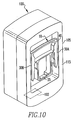
- Charger unit 100 having a plug 10 inserted into and held by recess 140 is shown in Figure 9, which is a rear elevational view, and Figure 10, which is a rear isometric view.
- recess 140 has a depth D as shown in Figure 8 that is at least as large as the height H, shown in Figure 3, of base 25 of plug 10 so that when plug 10 is inserted into and held by recess 140, no part of base 25 of plug 10 will protrude over the top edge 150 of recess 140.
- distances D1 and D2 measured from the center of sockets 145A and 145B to the first and second end, respectively, of recess 140 are sufficiently large enough to enable a user to hold base 25 of plug 10 with two or more fingers and insert prongs 15A and 15B into sockets 145A and 145B, and to subsequently remove plug 10 from recess 140 when desired.
- many plugs such as plug 10 are not symmetrical, meaning that prongs 15A and 15B are not positioned in the middle of base 25, but instead are slightly offset toward the top of base 25 (away form lip portion 35).
- each distance D 1 and D2 is made large enough to allow the insertion of plug 10 with the top side of base 25 either up or down.
- each of the distances D1 and D2 must be greater than a distance D3 (plus some manufacturing tolerance), wherein, as seen in Figure 3, the distance D3 is the distance from the middle of prongs 15A and 15B to the bottom of base 25.
- the distances D1 and D2 are not made sufficiently large, base 25 will not be able to be fit within recess 140 in one of the two insertion positions.
- recess 140 may be provided on rear face 115 of housing 105, each one being configured to hold a different type of plug.
- recess 140 may be provided in a location other than rear face 115, such on the same face (front face 110) to which the plug 10 may be attached for charging purposes.
- FIGs 11 and 12 show charger unit 100' according to an alternative embodiment of the present invention.
- Charger unit 100' is identical to charger unit 100 except that recess 140' includes secondary recesses 160A and 160B.
- a plateau surface 162 is provided between the secondary recesses 160A and 160B, and includes sockets 145A'and 145B'.
- recesses 160A and 160B provide a space in which a user may insert part of a finger in order to more easily remove plug 10 from recess 140'.
- a mechanism for securing plug 10 in place when prongs 15A and 15B are inserted into sockets 145A and 145B.
- One embodiment of such a mechanism shown in Figure 13, utilizes a spring element 155 to secure plug 10 in place.
- Spring element 155 includes attaching portion (not shown) and spring fingers 165A and 165B, each having a spring pin 170A and 170B.
- the attaching portion is configured to wrap around the exterior of a socket 145A or 145B to secure spring element 155 thereto.
- spring pins 170A and 170B When so secured, as seen in Figure 13, spring pins 170A and 170B will be aligned with a respective hole 175A or 175B provided in the exterior of socket 145A or 145B.
- Spring fingers 165A and 165B, and in particular spring pins 170A and 170B engage holes 180A and 180B provided in prongs 15A and 15B when prongs 15A and 15B are inserted into sockets 145A and 145B.
- the force of spring fingers 165A and 165B is sufficient to hold plug 10 in place within recess 140 under normal conditions.
- a user When it is desired to remove plug 10 from recess 140, a user must apply a pulling force sufficient to overcome the force of the spring fingers 165A and 165B.
- other known securing mechanisms such as other spring configurations or one or more magnets provided in socket 145A or 145B, may be used instead of the mechanism shown in Figure 13.
Landscapes
- Engineering & Computer Science (AREA)
- Power Engineering (AREA)
- Microelectronics & Electronic Packaging (AREA)
- Charge And Discharge Circuits For Batteries Or The Like (AREA)
Priority Applications (10)
| Application Number | Priority Date | Filing Date | Title |
|---|---|---|---|
| DE602005025536T DE602005025536D1 (de) | 2005-03-03 | 2005-03-03 | Ladeeinheit für eine elektronische Vorrichtung mit einem System zur geschützten Aufbewahrung eines Adaptersteckers |
| DE602005002926T DE602005002926T2 (de) | 2005-03-03 | 2005-03-03 | Ladeeinheit für ein elektronisches Gerät mit einer geschützten Unterbringung eines Adaptersteckers |
| EP07112800A EP1858133B1 (de) | 2005-03-03 | 2005-03-03 | Ladeeinheit für eine elektronische Vorrichtung mit einem System zur geschützten Aufbewahrung eines Adaptersteckers |
| EP05251262A EP1699123B1 (de) | 2005-03-03 | 2005-03-03 | Ladeeinheit für ein elektronisches Gerät mit einer geschützten Unterbringung eines Adaptersteckers |
| AT05251262T ATE376276T1 (de) | 2005-03-03 | 2005-03-03 | Ladeeinheit für ein elektronisches gerät mit einer geschützten unterbringung eines adaptersteckers |
| DE602005025535T DE602005025535D1 (de) | 2005-03-03 | 2005-03-03 | Ladeeinheit für eine elektronische Vorrichtung mit einem System zur geschützten Aufbewahrung eines Adaptersteckers |
| EP07112799A EP1852955B1 (de) | 2005-03-03 | 2005-03-03 | Ladeeinheit für eine elektronische Vorrichtung mit einem System zur geschützten Aufbewahrung eines Adaptersteckers |
| AT07112800T ATE492932T1 (de) | 2005-03-03 | 2005-03-03 | Ladeeinheit für eine elektronische vorrichtung mit einem system zur geschützten aufbewahrung eines adaptersteckers |
| AT07112799T ATE492931T1 (de) | 2005-03-03 | 2005-03-03 | Ladeeinheit für eine elektronische vorrichtung mit einem system zur geschützten aufbewahrung eines adaptersteckers |
| CA002538508A CA2538508C (en) | 2005-03-03 | 2006-03-01 | Charger unit for an electronic device including a system for protective storage of an adapter plug |
Applications Claiming Priority (1)
| Application Number | Priority Date | Filing Date | Title |
|---|---|---|---|
| EP05251262A EP1699123B1 (de) | 2005-03-03 | 2005-03-03 | Ladeeinheit für ein elektronisches Gerät mit einer geschützten Unterbringung eines Adaptersteckers |
Related Child Applications (2)
| Application Number | Title | Priority Date | Filing Date |
|---|---|---|---|
| EP07112799A Division EP1852955B1 (de) | 2005-03-03 | 2005-03-03 | Ladeeinheit für eine elektronische Vorrichtung mit einem System zur geschützten Aufbewahrung eines Adaptersteckers |
| EP07112800A Division EP1858133B1 (de) | 2005-03-03 | 2005-03-03 | Ladeeinheit für eine elektronische Vorrichtung mit einem System zur geschützten Aufbewahrung eines Adaptersteckers |
Publications (2)
| Publication Number | Publication Date |
|---|---|
| EP1699123A1 true EP1699123A1 (de) | 2006-09-06 |
| EP1699123B1 EP1699123B1 (de) | 2007-10-17 |
Family
ID=34940538
Family Applications (3)
| Application Number | Title | Priority Date | Filing Date |
|---|---|---|---|
| EP05251262A Expired - Lifetime EP1699123B1 (de) | 2005-03-03 | 2005-03-03 | Ladeeinheit für ein elektronisches Gerät mit einer geschützten Unterbringung eines Adaptersteckers |
| EP07112799A Expired - Lifetime EP1852955B1 (de) | 2005-03-03 | 2005-03-03 | Ladeeinheit für eine elektronische Vorrichtung mit einem System zur geschützten Aufbewahrung eines Adaptersteckers |
| EP07112800A Expired - Lifetime EP1858133B1 (de) | 2005-03-03 | 2005-03-03 | Ladeeinheit für eine elektronische Vorrichtung mit einem System zur geschützten Aufbewahrung eines Adaptersteckers |
Family Applications After (2)
| Application Number | Title | Priority Date | Filing Date |
|---|---|---|---|
| EP07112799A Expired - Lifetime EP1852955B1 (de) | 2005-03-03 | 2005-03-03 | Ladeeinheit für eine elektronische Vorrichtung mit einem System zur geschützten Aufbewahrung eines Adaptersteckers |
| EP07112800A Expired - Lifetime EP1858133B1 (de) | 2005-03-03 | 2005-03-03 | Ladeeinheit für eine elektronische Vorrichtung mit einem System zur geschützten Aufbewahrung eines Adaptersteckers |
Country Status (4)
| Country | Link |
|---|---|
| EP (3) | EP1699123B1 (de) |
| AT (3) | ATE492931T1 (de) |
| CA (1) | CA2538508C (de) |
| DE (3) | DE602005025535D1 (de) |
Cited By (1)
| Publication number | Priority date | Publication date | Assignee | Title |
|---|---|---|---|---|
| EP3229337B1 (de) * | 2016-04-07 | 2023-01-11 | Robert Bosch GmbH | Ladegerät |
Citations (4)
| Publication number | Priority date | Publication date | Assignee | Title |
|---|---|---|---|---|
| GB1518723A (en) * | 1975-07-18 | 1978-07-26 | Bausch & Lomb | Apparatus for disinfection of hydrophilic contact lenses |
| US4973827A (en) * | 1988-10-26 | 1990-11-27 | Asahi Irika Co., Ltd. | Disinfector units for contact lenses |
| US20030142817A1 (en) * | 2002-01-31 | 2003-07-31 | Liao Sheng Hsin | Earphone cable-receiving device with power recharge function |
| EP1372254A2 (de) * | 2002-06-10 | 2003-12-17 | Comarco Wireless Technologies, Inc. | Programmierbare zur Aufnahme von Wechsel- und Gleichspannung geeignete Spannungsversorgung |
-
2005
- 2005-03-03 DE DE602005025535T patent/DE602005025535D1/de not_active Expired - Lifetime
- 2005-03-03 DE DE602005002926T patent/DE602005002926T2/de not_active Expired - Lifetime
- 2005-03-03 EP EP05251262A patent/EP1699123B1/de not_active Expired - Lifetime
- 2005-03-03 DE DE602005025536T patent/DE602005025536D1/de not_active Expired - Lifetime
- 2005-03-03 AT AT07112799T patent/ATE492931T1/de not_active IP Right Cessation
- 2005-03-03 EP EP07112799A patent/EP1852955B1/de not_active Expired - Lifetime
- 2005-03-03 EP EP07112800A patent/EP1858133B1/de not_active Expired - Lifetime
- 2005-03-03 AT AT07112800T patent/ATE492932T1/de not_active IP Right Cessation
- 2005-03-03 AT AT05251262T patent/ATE376276T1/de not_active IP Right Cessation
-
2006
- 2006-03-01 CA CA002538508A patent/CA2538508C/en not_active Expired - Lifetime
Patent Citations (4)
| Publication number | Priority date | Publication date | Assignee | Title |
|---|---|---|---|---|
| GB1518723A (en) * | 1975-07-18 | 1978-07-26 | Bausch & Lomb | Apparatus for disinfection of hydrophilic contact lenses |
| US4973827A (en) * | 1988-10-26 | 1990-11-27 | Asahi Irika Co., Ltd. | Disinfector units for contact lenses |
| US20030142817A1 (en) * | 2002-01-31 | 2003-07-31 | Liao Sheng Hsin | Earphone cable-receiving device with power recharge function |
| EP1372254A2 (de) * | 2002-06-10 | 2003-12-17 | Comarco Wireless Technologies, Inc. | Programmierbare zur Aufnahme von Wechsel- und Gleichspannung geeignete Spannungsversorgung |
Cited By (1)
| Publication number | Priority date | Publication date | Assignee | Title |
|---|---|---|---|---|
| EP3229337B1 (de) * | 2016-04-07 | 2023-01-11 | Robert Bosch GmbH | Ladegerät |
Also Published As
| Publication number | Publication date |
|---|---|
| EP1699123B1 (de) | 2007-10-17 |
| EP1858133B1 (de) | 2010-12-22 |
| ATE492931T1 (de) | 2011-01-15 |
| DE602005025535D1 (de) | 2011-02-03 |
| DE602005025536D1 (de) | 2011-02-03 |
| ATE376276T1 (de) | 2007-11-15 |
| CA2538508C (en) | 2009-01-06 |
| EP1852955A1 (de) | 2007-11-07 |
| EP1852955B1 (de) | 2010-12-22 |
| EP1858133A1 (de) | 2007-11-21 |
| CA2538508A1 (en) | 2006-09-03 |
| DE602005002926D1 (de) | 2007-11-29 |
| DE602005002926T2 (de) | 2008-07-24 |
| ATE492932T1 (de) | 2011-01-15 |
Similar Documents
| Publication | Publication Date | Title |
|---|---|---|
| US7688030B2 (en) | Charger unit for an electronic device including a system for protective storage of an adapter plug | |
| TWI295869B (en) | Connector charger | |
| CN206302171U (zh) | 便携式充电外壳模块 | |
| EP2773084B1 (de) | Batterie-ladestation für mobile informationsendgeräte | |
| KR100415989B1 (ko) | 컴퓨터고유배터리팩또는일반배터리를사용할수있는휴대형컴퓨터 | |
| US20130157483A1 (en) | Power plug, electrical plug assembly and electrical charger assembly | |
| JP6905097B2 (ja) | 充電アダプタ及び充電装置 | |
| US20140356667A1 (en) | Auxiliary battery device for electronic device | |
| EP1814016A1 (de) | Tragbare Stromversorgungseinrichtung für USB-Geräte | |
| JPH07504065A (ja) | エネルギーパック及び電池用カートリッジ | |
| US20230299599A1 (en) | Mobile power supply device | |
| JP4517265B2 (ja) | 電源変換アダプタ装置 | |
| CN112311040A (zh) | 一种多功能无线充电器 | |
| US20060208697A1 (en) | Gangable charger | |
| US20090051318A1 (en) | Pass Around Electrical Contacts | |
| WO1999066605A1 (en) | Plug assembly | |
| CA2538508C (en) | Charger unit for an electronic device including a system for protective storage of an adapter plug | |
| KR101848726B1 (ko) | 탈착을 통한 가변용량형 보조배터리 및 보조배터리 장치 | |
| CN220477089U (zh) | 智能眼镜盒 | |
| KR19990039777U (ko) | 휴대폰의 다기종 겸용 충전기 | |
| CN215646267U (zh) | 便携式移动电源 | |
| JP2008112654A (ja) | 二次電池装置および携帯型電子機器 | |
| CN213279220U (zh) | 多用租赁充电宝 | |
| CN211166041U (zh) | 带充电功能的笔记本 | |
| CN224191318U (zh) | 电子设备配件 |
Legal Events
| Date | Code | Title | Description |
|---|---|---|---|
| PUAI | Public reference made under article 153(3) epc to a published international application that has entered the european phase |
Free format text: ORIGINAL CODE: 0009012 |
|
| 17P | Request for examination filed |
Effective date: 20050323 |
|
| AK | Designated contracting states |
Kind code of ref document: A1 Designated state(s): AT BE BG CH CY CZ DE DK EE ES FI FR GB GR HU IE IS IT LI LT LU MC NL PL PT RO SE SI SK TR |
|
| AX | Request for extension of the european patent |
Extension state: AL BA HR LV MK YU |
|
| GRAP | Despatch of communication of intention to grant a patent |
Free format text: ORIGINAL CODE: EPIDOSNIGR1 |
|
| AKX | Designation fees paid |
Designated state(s): AT BE BG CH CY CZ DE DK EE ES FI FR GB GR HU IE IS IT LI LT LU MC NL PL PT RO SE SI SK TR |
|
| AXX | Extension fees paid |
Extension state: HR Payment date: 20070306 Extension state: AL Payment date: 20070306 Extension state: BA Payment date: 20070306 Extension state: YU Payment date: 20070306 Extension state: MK Payment date: 20070306 Extension state: LV Payment date: 20070306 |
|
| GRAS | Grant fee paid |
Free format text: ORIGINAL CODE: EPIDOSNIGR3 |
|
| GRAA | (expected) grant |
Free format text: ORIGINAL CODE: 0009210 |
|
| AK | Designated contracting states |
Kind code of ref document: B1 Designated state(s): AT BE BG CH CY CZ DE DK EE ES FI FR GB GR HU IE IS IT LI LT LU MC NL PL PT RO SE SI SK TR |
|
| AX | Request for extension of the european patent |
Extension state: AL BA HR LV MK YU |
|
| REG | Reference to a national code |
Ref country code: GB Ref legal event code: FG4D |
|
| REG | Reference to a national code |
Ref country code: CH Ref legal event code: EP |
|
| REG | Reference to a national code |
Ref country code: IE Ref legal event code: FG4D |
|
| REF | Corresponds to: |
Ref document number: 602005002926 Country of ref document: DE Date of ref document: 20071129 Kind code of ref document: P |
|
| NLV1 | Nl: lapsed or annulled due to failure to fulfill the requirements of art. 29p and 29m of the patents act | ||
| PG25 | Lapsed in a contracting state [announced via postgrant information from national office to epo] |
Ref country code: LI Free format text: LAPSE BECAUSE OF FAILURE TO SUBMIT A TRANSLATION OF THE DESCRIPTION OR TO PAY THE FEE WITHIN THE PRESCRIBED TIME-LIMIT Effective date: 20071017 Ref country code: SE Free format text: LAPSE BECAUSE OF FAILURE TO SUBMIT A TRANSLATION OF THE DESCRIPTION OR TO PAY THE FEE WITHIN THE PRESCRIBED TIME-LIMIT Effective date: 20080117 Ref country code: CH Free format text: LAPSE BECAUSE OF FAILURE TO SUBMIT A TRANSLATION OF THE DESCRIPTION OR TO PAY THE FEE WITHIN THE PRESCRIBED TIME-LIMIT Effective date: 20071017 Ref country code: NL Free format text: LAPSE BECAUSE OF FAILURE TO SUBMIT A TRANSLATION OF THE DESCRIPTION OR TO PAY THE FEE WITHIN THE PRESCRIBED TIME-LIMIT Effective date: 20071017 Ref country code: ES Free format text: LAPSE BECAUSE OF FAILURE TO SUBMIT A TRANSLATION OF THE DESCRIPTION OR TO PAY THE FEE WITHIN THE PRESCRIBED TIME-LIMIT Effective date: 20080128 |
|
| REG | Reference to a national code |
Ref country code: CH Ref legal event code: PL |
|
| PG25 | Lapsed in a contracting state [announced via postgrant information from national office to epo] |
Ref country code: SI Free format text: LAPSE BECAUSE OF FAILURE TO SUBMIT A TRANSLATION OF THE DESCRIPTION OR TO PAY THE FEE WITHIN THE PRESCRIBED TIME-LIMIT Effective date: 20071017 Ref country code: LT Free format text: LAPSE BECAUSE OF FAILURE TO SUBMIT A TRANSLATION OF THE DESCRIPTION OR TO PAY THE FEE WITHIN THE PRESCRIBED TIME-LIMIT Effective date: 20071017 Ref country code: BG Free format text: LAPSE BECAUSE OF FAILURE TO SUBMIT A TRANSLATION OF THE DESCRIPTION OR TO PAY THE FEE WITHIN THE PRESCRIBED TIME-LIMIT Effective date: 20080117 Ref country code: PL Free format text: LAPSE BECAUSE OF FAILURE TO SUBMIT A TRANSLATION OF THE DESCRIPTION OR TO PAY THE FEE WITHIN THE PRESCRIBED TIME-LIMIT Effective date: 20071017 Ref country code: PT Free format text: LAPSE BECAUSE OF FAILURE TO SUBMIT A TRANSLATION OF THE DESCRIPTION OR TO PAY THE FEE WITHIN THE PRESCRIBED TIME-LIMIT Effective date: 20080317 Ref country code: IS Free format text: LAPSE BECAUSE OF FAILURE TO SUBMIT A TRANSLATION OF THE DESCRIPTION OR TO PAY THE FEE WITHIN THE PRESCRIBED TIME-LIMIT Effective date: 20080217 |
|
| PG25 | Lapsed in a contracting state [announced via postgrant information from national office to epo] |
Ref country code: AT Free format text: LAPSE BECAUSE OF FAILURE TO SUBMIT A TRANSLATION OF THE DESCRIPTION OR TO PAY THE FEE WITHIN THE PRESCRIBED TIME-LIMIT Effective date: 20071017 |
|
| ET | Fr: translation filed | ||
| PG25 | Lapsed in a contracting state [announced via postgrant information from national office to epo] |
Ref country code: DK Free format text: LAPSE BECAUSE OF FAILURE TO SUBMIT A TRANSLATION OF THE DESCRIPTION OR TO PAY THE FEE WITHIN THE PRESCRIBED TIME-LIMIT Effective date: 20071017 Ref country code: CZ Free format text: LAPSE BECAUSE OF FAILURE TO SUBMIT A TRANSLATION OF THE DESCRIPTION OR TO PAY THE FEE WITHIN THE PRESCRIBED TIME-LIMIT Effective date: 20071017 |
|
| PLBE | No opposition filed within time limit |
Free format text: ORIGINAL CODE: 0009261 |
|
| STAA | Information on the status of an ep patent application or granted ep patent |
Free format text: STATUS: NO OPPOSITION FILED WITHIN TIME LIMIT |
|
| PG25 | Lapsed in a contracting state [announced via postgrant information from national office to epo] |
Ref country code: RO Free format text: LAPSE BECAUSE OF FAILURE TO SUBMIT A TRANSLATION OF THE DESCRIPTION OR TO PAY THE FEE WITHIN THE PRESCRIBED TIME-LIMIT Effective date: 20071017 Ref country code: BE Free format text: LAPSE BECAUSE OF FAILURE TO SUBMIT A TRANSLATION OF THE DESCRIPTION OR TO PAY THE FEE WITHIN THE PRESCRIBED TIME-LIMIT Effective date: 20071017 Ref country code: SK Free format text: LAPSE BECAUSE OF FAILURE TO SUBMIT A TRANSLATION OF THE DESCRIPTION OR TO PAY THE FEE WITHIN THE PRESCRIBED TIME-LIMIT Effective date: 20071017 |
|
| 26N | No opposition filed |
Effective date: 20080718 |
|
| PG25 | Lapsed in a contracting state [announced via postgrant information from national office to epo] |
Ref country code: MC Free format text: LAPSE BECAUSE OF NON-PAYMENT OF DUE FEES Effective date: 20080331 |
|
| PG25 | Lapsed in a contracting state [announced via postgrant information from national office to epo] |
Ref country code: EE Free format text: LAPSE BECAUSE OF FAILURE TO SUBMIT A TRANSLATION OF THE DESCRIPTION OR TO PAY THE FEE WITHIN THE PRESCRIBED TIME-LIMIT Effective date: 20071017 Ref country code: IE Free format text: LAPSE BECAUSE OF NON-PAYMENT OF DUE FEES Effective date: 20080303 Ref country code: GR Free format text: LAPSE BECAUSE OF FAILURE TO SUBMIT A TRANSLATION OF THE DESCRIPTION OR TO PAY THE FEE WITHIN THE PRESCRIBED TIME-LIMIT Effective date: 20080118 |
|
| PG25 | Lapsed in a contracting state [announced via postgrant information from national office to epo] |
Ref country code: FI Free format text: LAPSE BECAUSE OF FAILURE TO SUBMIT A TRANSLATION OF THE DESCRIPTION OR TO PAY THE FEE WITHIN THE PRESCRIBED TIME-LIMIT Effective date: 20071017 |
|
| PG25 | Lapsed in a contracting state [announced via postgrant information from national office to epo] |
Ref country code: CY Free format text: LAPSE BECAUSE OF FAILURE TO SUBMIT A TRANSLATION OF THE DESCRIPTION OR TO PAY THE FEE WITHIN THE PRESCRIBED TIME-LIMIT Effective date: 20071017 |
|
| PG25 | Lapsed in a contracting state [announced via postgrant information from national office to epo] |
Ref country code: LU Free format text: LAPSE BECAUSE OF NON-PAYMENT OF DUE FEES Effective date: 20080303 Ref country code: HU Free format text: LAPSE BECAUSE OF FAILURE TO SUBMIT A TRANSLATION OF THE DESCRIPTION OR TO PAY THE FEE WITHIN THE PRESCRIBED TIME-LIMIT Effective date: 20080418 |
|
| PG25 | Lapsed in a contracting state [announced via postgrant information from national office to epo] |
Ref country code: TR Free format text: LAPSE BECAUSE OF FAILURE TO SUBMIT A TRANSLATION OF THE DESCRIPTION OR TO PAY THE FEE WITHIN THE PRESCRIBED TIME-LIMIT Effective date: 20071017 |
|
| PG25 | Lapsed in a contracting state [announced via postgrant information from national office to epo] |
Ref country code: IT Free format text: LAPSE BECAUSE OF NON-PAYMENT OF DUE FEES Effective date: 20080331 |
|
| REG | Reference to a national code |
Ref country code: DE Ref legal event code: R082 Ref document number: 602005002926 Country of ref document: DE Representative=s name: MERH-IP MATIAS ERNY REICHL HOFFMANN, DE |
|
| REG | Reference to a national code |
Ref country code: DE Ref legal event code: R082 Ref document number: 602005002926 Country of ref document: DE Representative=s name: MERH-IP MATIAS ERNY REICHL HOFFMANN, DE Effective date: 20140925 Ref country code: DE Ref legal event code: R081 Ref document number: 602005002926 Country of ref document: DE Owner name: BLACKBERRY LIMITED, WATERLOO, CA Free format text: FORMER OWNER: RESEARCH IN MOTION LTD., WATERLOO, ONTARIO, CA Effective date: 20140925 Ref country code: DE Ref legal event code: R082 Ref document number: 602005002926 Country of ref document: DE Representative=s name: MERH-IP MATIAS ERNY REICHL HOFFMANN PATENTANWA, DE Effective date: 20140925 |
|
| REG | Reference to a national code |
Ref country code: FR Ref legal event code: PLFP Year of fee payment: 12 |
|
| REG | Reference to a national code |
Ref country code: FR Ref legal event code: PLFP Year of fee payment: 13 |
|
| REG | Reference to a national code |
Ref country code: FR Ref legal event code: PLFP Year of fee payment: 14 |
|
| PGFP | Annual fee paid to national office [announced via postgrant information from national office to epo] |
Ref country code: DE Payment date: 20240328 Year of fee payment: 20 Ref country code: GB Payment date: 20240319 Year of fee payment: 20 |
|
| REG | Reference to a national code |
Ref country code: DE Ref legal event code: R082 Ref document number: 602005002926 Country of ref document: DE Ref country code: DE Ref legal event code: R081 Ref document number: 602005002926 Country of ref document: DE Owner name: MALIKIE INNOVATIONS LTD., IE Free format text: FORMER OWNER: BLACKBERRY LIMITED, WATERLOO, ONTARIO, CA |
|
| PGFP | Annual fee paid to national office [announced via postgrant information from national office to epo] |
Ref country code: FR Payment date: 20240326 Year of fee payment: 20 |
|
| REG | Reference to a national code |
Ref country code: DE Ref legal event code: R071 Ref document number: 602005002926 Country of ref document: DE |
|
| REG | Reference to a national code |
Ref country code: GB Ref legal event code: PE20 Expiry date: 20250302 |
|
| PG25 | Lapsed in a contracting state [announced via postgrant information from national office to epo] |
Ref country code: GB Free format text: LAPSE BECAUSE OF EXPIRATION OF PROTECTION Effective date: 20250302 |