EP1699665B1 - Echelle de vehicule et vehicule comprenant une telle echelle - Google Patents
Echelle de vehicule et vehicule comprenant une telle echelle Download PDFInfo
- Publication number
- EP1699665B1 EP1699665B1 EP04809100A EP04809100A EP1699665B1 EP 1699665 B1 EP1699665 B1 EP 1699665B1 EP 04809100 A EP04809100 A EP 04809100A EP 04809100 A EP04809100 A EP 04809100A EP 1699665 B1 EP1699665 B1 EP 1699665B1
- Authority
- EP
- European Patent Office
- Prior art keywords
- steps
- rotation
- vehicle
- aforementioned
- ladder
- Prior art date
- Legal status (The legal status is an assumption and is not a legal conclusion. Google has not performed a legal analysis and makes no representation as to the accuracy of the status listed.)
- Expired - Lifetime
Links
- 230000001747 exhibiting effect Effects 0.000 claims abstract description 3
- 238000006073 displacement reaction Methods 0.000 claims description 14
- 230000000717 retained effect Effects 0.000 claims description 3
- 230000005484 gravity Effects 0.000 description 5
- 230000009194 climbing Effects 0.000 description 4
- 238000010276 construction Methods 0.000 description 2
- XAGFODPZIPBFFR-UHFFFAOYSA-N aluminium Chemical compound [Al] XAGFODPZIPBFFR-UHFFFAOYSA-N 0.000 description 1
- 229910052782 aluminium Inorganic materials 0.000 description 1
- 230000015572 biosynthetic process Effects 0.000 description 1
- 230000006835 compression Effects 0.000 description 1
- 238000007906 compression Methods 0.000 description 1
- 238000013016 damping Methods 0.000 description 1
- 230000001419 dependent effect Effects 0.000 description 1
- 230000000694 effects Effects 0.000 description 1
- 238000000034 method Methods 0.000 description 1
- 238000003466 welding Methods 0.000 description 1
Images



Classifications
-
- B—PERFORMING OPERATIONS; TRANSPORTING
- B60—VEHICLES IN GENERAL
- B60R—VEHICLES, VEHICLE FITTINGS, OR VEHICLE PARTS, NOT OTHERWISE PROVIDED FOR
- B60R3/00—Arrangements of steps or ladders facilitating access to or on the vehicle, e.g. running-boards
- B60R3/02—Retractable steps or ladders, e.g. movable under shock
Definitions
- the present invention relates to a vehicle ladder.
- vehicle ladder is used to denote a ladder that is mounted on large vehicles for the purpose of facilitating access to parts of the vehicle, for example next to the entrance to the cab, in order to provide access to engine covers, the roof or load areas in an elevated position.
- the invention also relates to a vehicle on which a ladder of this kind has been mounted.
- a ladder of this kind is thus arranged essentially vertically with steps positioned vertically one above the other.
- a driver or other passenger intends to enter the cab, he must lean backwards slightly in order to enable him to place his feet on the steps.
- the center of gravity of the person using the ladder is situated outside the surface of the steps. Because the center of gravity is situated outside the step, the driver or other user of the ladder must use his hands in order to maintain a hold on the ladder.
- a vehicle ladder comprising one step only, according to the preamble of claim 1, is known from US 3 980 319 A .
- the object of the invention is to make available an improved vehicle ladder to facilitate gaining entry into a vehicle cab, for example, where the ladder is executed in such a way that, when it is not in use, it exhibits steps which lie close to the essentially vertical side walls of the vehicle, and where, when they are in use, the steps are positioned in such a way that the center of gravity of the user can be situated within the step.
- a vehicle ladder is used with a step exhibiting a first end, which is attached to a retaining device, and a second free end.
- the first end is pivotally attached to the retaining device about an axis of rotation. This means that the outer free end of the step can be caused to rotate outwards from the vehicle body, in conjunction with which it is possible to position the center of gravity on, rather than outside the step.
- the step is so arranged, when a load is applied along the axis of rotation of the step, as to be caused to rotate about the aforementioned axis of rotation from an unloaded rest position to a stop position corresponding to maximum rotation of the aforementioned at least one step.
- the step is suspended in such a way as to be capable of displacement along the aforementioned axis of rotation in a retaining device.
- the retaining device comprises means for bringing about the simultaneous rotation of the step in conjunction with displacement of the step along the axis of rotation.
- this means consists of a screw-shaped track or groove arranged concentrically around the axis of rotation, which screw-shaped track or groove is so arranged as to interact with a supporting flange.
- Mutual displacement of the supporting flange and the track or the groove along the axis of rotation in this way brings about a rotating movement between the supporting flange and the track or the groove.
- the retaining device associated with the step comprises a spring device that is so arranged as to cause the step to return to the unloaded rest position.
- the retaining device can also be equipped with a damper, which is so arranged as to delay the return of the step from the stop position to the unloaded rest position.
- the vehicle ladder comprises at least two steps, each of which is so arranged, when subjected to loading along an axis of rotation, as to be caused to rotate about an axis of rotation from an unloaded rest position to a stop position corresponding to the maximum rotation of the steps.
- the steps are so arranged as to be capable of being caused to rotate independently of one another, in conjunction with which the positioning of the steps can be displaced from being situated above one another into a position in which the rotatable steps exhibit an angle between one another.
- each of the steps is arranged with a maximum angle of rotation from the aforementioned rest position to the aforementioned maximum rotation, and in that the maximum angle of rotation increases for consecutive steps in the direction of the axis of rotation.
- a vehicle ladder of this kind is so arranged as to be mounted on a vehicle so that the maximum angle of rotation is greatest for steps closest to the ground. This means that the lowest step will be caused to rotate outwards to the greatest extent.
- the vehicle ladder exhibits steps having a length between the aforementioned first and second ends which reduces for every consecutive step in the direction of the axis of rotation.
- the vehicle ladder can be mounted so that the length of the steps is shortest for steps nearest the ground.
- a space between a vertical upright, which supports the steps and the retaining devices, and the wheel housing can be used for steps which extend in between.
- This embodiment may be combined advantageously with the embodiment in which the maximum angle of rotation is greatest for the step that is positioned closest to the ground, as it is possible in this way to ensure that the outer end of lower steps can be caused to rotate outwards at least as far as superjacent steps.
- each of the steps exhibits a retaining device containing a spring device.
- the spring devices are so arranged, in the event of the consecutive loading of the steps from a first step, which is intended to be positioned nearest the ground when the steps are mounted on a vehicle in an upward direction, as to be subjected to a load consecutively one after the other, in conjunction with which the displacement of each step takes place against one spring device at a time. This can be achieved by compressing the spring device for a bottom step, in conjunction with which the step is caused to be displaced downwards. In this position, there is no contact between the bottom step and the next step.
- the ladder is executed so that none of the steps is capable, when a loading is applied to a step which lies above other steps, of being displaced downwards without ensuring that all the subjacent steps have been displaced downwards.
- FIG. 1 Illustrated in Figure 1 is a vehicle ladder 1 in accordance with the invention viewed from the side.
- the vehicle ladder comprises three steps 2a, 2b, 2c positioned above one another.
- the steps 2a - 2c exhibit a first end 3a - 3c, which is attached to a retaining device 4, and a second free end 5a - 5c.
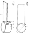
- the retaining device 4 is executed from a tube 6, which exhibits grooves 7 into which a peg 8 (Fig. 4) or a pin are introduced.
- a partially cut-away view of the bottom sleeve is shown in Figure 1, in which the groove 7 is visible.
- Shown in detail in Figure 2 is the tube 6 with a groove 7, into which a supporting flange 8, for example in the form of a peg or pin belonging to a step 2a - 2c, must engage.
- a transcurrent pin which is indicated with a broken line in Figure 4
- the tube must be executed with diametrically opposing grooves.
- the peg 8 or the pin is attached to or executed on a sleeve 9.
- the sleeve 9 is attached to or integrated into the first end 3a - 3c of the respective step 2a - 2c.
- Each of the steps 2a - 2c thus comprises a step plate 10 and a sleeve 9 (Fig. 3).
- the sleeve 9 and the step plate 10 may be executed in a single piece, for example as a cast aluminum component.
- the step plate 10 and the sleeve can also be joined together in a previously disclosed fashion, for example by welding or with a screwed joint.
- the sleeve 9 is positioned concentrically around the tube 6 with a peg 8 or pin engaging in an associated groove 7 positioned in the material of the tube.
- a suitable height for the groove is thus ca. 1.5 - 4 cm.
- a suitable angle of opening f is dependent on which step 2a - 2c is intended and on the length of the step. Suitable angles of opening are preferably between 5 and 60°.
- the step 2a - 2c can be equipped with a supporting flange 15, which runs from the sleeve 9 in the direction of the free end 5a - 5c of the step 2a - 2c.
- Figure 5 shows a vehicle ladder 1 with spring devices 16a - 16c for returning the steps 2a - 2c to rest positions and with grooves 7 which are so arranged as to interact with pegs (not shown) for bringing about a rotating movement in conjunction with the axial loading of the steps.
- the spring devices 16a - 16c are attached at their one end to the tube 6, for example to a supporting flange 17a - 17c formed on the tube.
- the other end of the spring devices 16a - 16c is attached to the respective step 2a - 2c, appropriately by being attached to the peg 8 or pin which runs in the groove 7.
- the spring devices 16a - 16c ensure that the steps are returned to their rest position when the step is not under load.
- Illustrated in Figure 6 are the two upper steps 2a, 2b in their respective uploaded rest positions, while the step 2c has adopted its outward-rotated stop position.
- the tube 6 is illustrated here in a cut-away view, and the spring device belonging to the step 2c is shown in its unloaded condition.
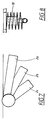
- Illustrated in Figure 7 are three steps 2a - 2c in their respective stop positions.
- the sleeves 9 of the respective steps are positioned in contact with one another when the steps are unloaded.
- this step is caused to be displaced from the steps which lie above the step 2c. This takes place under loading of the spring device 16, while the other spring devices remain unloaded.
- a damper 18 (Fig. 8) is so arranged as to interact with the respective spring device. The damper is so arranged as to delay the return of the steps from the stop position to the unloaded rest position.
- the step 2c remains for a time in its compressed position, in conjunction with which the step 2b can be displaced only during loading of the spring device 16b which belongs to the step 2b.
- the same procedure is repeated during loading of the third step 2a, in conjunction with which the latter can be forced down only during loading of the spring device 16a.
- the damper can be executed as shown in Figure 8 as a viscous piston damper, of which one end is attached to the tube and the other end is attached to the step.
- the existing friction and damping between the tube and the sleeve may also be found to be sufficient.
- step 2a In the event that the steps 2a - 2c are loaded in a direction from above, displacement of the step 2a will require the displacement of the steps that are situated below this loaded step. Because they have not yet been displaced and are still retained by the damper, all the steps must accordingly be displaced jointly during the loading of all the spring devices. This will mean that the step is perceived as being stable when stepping out onto it.
- the spring devices are of a sufficiently slender execution to enable a user to compress all the spring devices with his own weight.
- the grooves can be executed so that the angle of opening becomes proportionally greater the closer a step is positioned in relation to the ground. In this case, a stair formation will be unfolded in conjunction with loading of the top step.
- Illustrated in Figure 9 is a truck 20 which is carrying a vehicle ladder 1 in accordance with the above description.
- the vehicle ladder 1 is mounted in conjunction with a wheel housing 21.
- the tube 6 runs at a distance from the wheel housing 21, and the steps are executed with a length that is adapted to the space that is present between the wheel housing and the tube 6.
- a current or voltage sensor can be connected to the entrance to provide a warning in the event of unwelcome visits such as attempted robbery or burglary.
Landscapes
- Engineering & Computer Science (AREA)
- Mechanical Engineering (AREA)
- Vehicle Step Arrangements And Article Storage (AREA)
- Ladders (AREA)
- Vehicle Interior And Exterior Ornaments, Soundproofing, And Insulation (AREA)
Claims (13)
- Echelle de véhicule comportant au moins une marche (2a à 2c) présentant une première extrémité (3a à 3c), qui est fixée de manière pivotante autour d'un axe de rotation (11) à un dispositif de retenue (4), et une seconde extrémité libre (5a à 5c), caractérisée en ce que la au moins une marche mentionnée ci-dessus (2a à 2c) est agencée de manière à être amenée, lorsqu'elle est soumise à une charge le long de l'axe de rotation (11), à tourner autour de l'axe de rotation mentionné ci-dessus (11) à partir d'une position de repos non chargée jusque dans une position d'arrêt correspondant à une rotation maximum de la au moins une marche mentionnée ci-dessus (2a à 2c).
- Echelle de véhicule selon la revendication 1, caractérisée en ce que la au moins une marche mentionnée ci-dessus est suspendue dans son dispositif de retenue (4) de manière à être capable d'un déplacement le long de l'axe de rotation mentionné ci-dessus (11), et en ce que le dispositif de retenue mentionné ci-dessus comporte des moyens (6, 7, 8) pour provoquer la rotation simultanée de la au moins une marche mentionnée ci-dessus (2a à 2c) en association avec un déplacement de la au moins une marche mentionnée ci-dessus le long de l'axe de rotation mentionné ci-dessus.
- Echelle de véhicule selon la revendication 2, caractérisée en ce que les moyens mentionnés ci-dessus sont constitués d'une piste ou gorge en forme de vis (7) qui s'étend coaxialement autour de l'axe de rotation, laquelle piste ou gorge en forme de vis (7) est agencée de manière à interagir avec un rebord de support (8), interaction en association avec laquelle le déplacement mutuel du rebord de support (8) et de la piste ou de la gorge (7) le long de l'axe de rotation (11) provoque un déplacement de rotation entre le rebord de support et la piste ou la gorge.
- Echelle de véhicule selon l'une quelconque des revendications 1 à 3, caractérisée en ce que le dispositif de retenue (4) comporte un dispositif à ressort (16a à 16c) qui est agencé de manière à amener la au moins une marche mentionnée ci-dessus (2a à 2c) à retourner vers la position de repos non chargée mentionnée ci-dessus.
- Echelle de véhicule selon l'une quelconque des revendications précédentes, caractérisée en ce que l'échelle de véhicule mentionnée ci-dessus comporte au moins deux marches (2a, 2b), qui sont chacune agencées, lorsqu'elles sont soumises à une charge autour d'un axe de rotation, de manière à être amenées à tourner autour de l'axe de rotation mentionné ci-dessus à partir d'une position de repos non chargée vers une position d'arrêt correspondant à la rotation maximum (f) desdites au moins deux marches mentionnées ci-dessus.
- Echelle de véhicule selon la revendication 5, caractérisée en ce que chacune des marches présente un angle de rotation maximum (f) à partir de la position de repos mentionnée ci-dessus vers la rotation maximum mentionnée ci-dessus, et en ce que l'angle maximum de rotation augmente pour des marches consécutives dans la direction de l'axe de rotation.
- Echelle de véhicule selon la revendication 6, caractérisée en ce que l'échelle de véhicule est agencée de manière à être montée sur un véhicule de sorte que l'angle de rotation maximum est le plus important pour les marches les plus proches du sol.
- Echelle de véhicule selon l'une quelconque des revendications 5 à 7, caractérisée en ce que l'échelle de véhicule comporte des marches ayant une longueur entre les première (3a à 3c) et seconde (5a à 5c) extrémités mentionnées ci-dessus qui diminue pour des marches consécutives dans la direction de l'axe de rotation.
- Echelle de véhicule selon la revendication 8, caractérisée en ce que l'échelle de véhicule est agencée de manière à être montée sur un véhicule de sorte que la longueur des marches est la plus courte pour les marches les plus proches du sol.
- Echelle de véhicule selon l'une quelconque des revendications 5 à 7, caractérisée en ce que chacune des marches présente un dispositif de retenue (4) contenant un dispositif à ressort (6a à 6c) qui est agencé, dans le cas de la charge consécutive des marches à partir d'une première marche (2c) qui est prévue pour être positionnée la plus proche du sol lorsque les marches sont montées sur un véhicule (20) dans une direction vers le haut, de manière à être soumises à une charge consécutivement les unes après les autres, en association avec quoi le déplacement de chaque marche (2a à 2c) a lieu contre un dispositif à ressort (6a à 6c) à un moment, et en ce que dans le cas de la charge consécutive des marches à partir d'une première marche (2a) qui est prévue pour être positionnée la plus éloignée du sol lorsque les marches sont montées sur un véhicule dans une direction vers le bas, une charge est appliquée à tous les dispositifs à ressort (6a à 6c) appartenant à une marche chargée, et de quelconques marches qui sont situées sous la marche chargée.
- Echelle de véhicule selon la revendication 10, caractérisée en ce que la marche (2c) qui est agencée de manière à être positionnée la plus proche du sol en association avec un montage sur un véhicule est retenue dans une position déchargée à l'aide du dispositif à ressort (6c) prévu pour cette marche, et en ce que les marches (2a, 2b) qui sont positionnées au-dessus de cette marche sont en appui contre la marche immédiatement sous-jacente (2b, 2c), et sont retenues dans leur position de repos à l'aide du dispositif à ressort (6b, 6c) prévu pour ces marches.
- Echelle de véhicule selon la revendication 10 ou 11, caractérisée en ce que les dispositifs de retenue comportent des amortisseurs (18) qui retardent le retour des marches à partir de la position d'arrêt vers la position de repos non chargée.
- Véhicule comportant une échelle de véhicule montée sur le véhicule selon l'une quelconque des revendications 1 à 12.
Applications Claiming Priority (2)
| Application Number | Priority Date | Filing Date | Title |
|---|---|---|---|
| SE0303450A SE526306C2 (sv) | 2003-12-17 | 2003-12-17 | Fordonsstege och fordon innefattande fordonsstege |
| PCT/SE2004/001927 WO2005058647A1 (fr) | 2003-12-17 | 2004-12-17 | Echelle de vehicule et vehicule comprenant une telle echelle |
Publications (2)
| Publication Number | Publication Date |
|---|---|
| EP1699665A1 EP1699665A1 (fr) | 2006-09-13 |
| EP1699665B1 true EP1699665B1 (fr) | 2007-07-18 |
Family
ID=30768769
Family Applications (1)
| Application Number | Title | Priority Date | Filing Date |
|---|---|---|---|
| EP04809100A Expired - Lifetime EP1699665B1 (fr) | 2003-12-17 | 2004-12-17 | Echelle de vehicule et vehicule comprenant une telle echelle |
Country Status (6)
| Country | Link |
|---|---|
| EP (1) | EP1699665B1 (fr) |
| JP (1) | JP4554620B2 (fr) |
| AT (1) | ATE367286T1 (fr) |
| DE (1) | DE602004007688T2 (fr) |
| SE (1) | SE526306C2 (fr) |
| WO (1) | WO2005058647A1 (fr) |
Families Citing this family (1)
| Publication number | Priority date | Publication date | Assignee | Title |
|---|---|---|---|---|
| DE102014212988A1 (de) * | 2014-07-03 | 2016-01-21 | Volkswagen Aktiengesellschaft | Fahrzeug mit einer Einstiegsvorrichtung |
Family Cites Families (6)
| Publication number | Priority date | Publication date | Assignee | Title |
|---|---|---|---|---|
| US605428A (en) * | 1898-06-07 | Carriage-step | ||
| US3329443A (en) * | 1966-03-28 | 1967-07-04 | Lowder Elmo | Swing-out step for vehicle |
| US3980319A (en) * | 1975-07-23 | 1976-09-14 | R And L Accessories, Inc. | Folding step for high ground clearance vehicles |
| DE2910812A1 (de) * | 1979-03-20 | 1980-10-02 | Audi Nsu Auto Union Ag | Schwenkbares trittbrett |
| JPH0752713A (ja) * | 1993-08-20 | 1995-02-28 | Hitachi Constr Mach Co Ltd | 建設機械の昇降ステップ |
| US5897125A (en) * | 1997-07-31 | 1999-04-27 | Mid America Automotive Products, Inc. | Swivel truck step |
-
2003
- 2003-12-17 SE SE0303450A patent/SE526306C2/sv not_active IP Right Cessation
-
2004
- 2004-12-17 DE DE602004007688T patent/DE602004007688T2/de not_active Expired - Lifetime
- 2004-12-17 WO PCT/SE2004/001927 patent/WO2005058647A1/fr not_active Ceased
- 2004-12-17 JP JP2006545297A patent/JP4554620B2/ja not_active Expired - Fee Related
- 2004-12-17 EP EP04809100A patent/EP1699665B1/fr not_active Expired - Lifetime
- 2004-12-17 AT AT04809100T patent/ATE367286T1/de not_active IP Right Cessation
Also Published As
| Publication number | Publication date |
|---|---|
| DE602004007688T2 (de) | 2008-04-10 |
| WO2005058647A1 (fr) | 2005-06-30 |
| DE602004007688D1 (de) | 2007-08-30 |
| EP1699665A1 (fr) | 2006-09-13 |
| SE526306C2 (sv) | 2005-08-16 |
| JP4554620B2 (ja) | 2010-09-29 |
| SE0303450D0 (sv) | 2003-12-17 |
| SE0303450L (sv) | 2005-06-18 |
| ATE367286T1 (de) | 2007-08-15 |
| JP2007514609A (ja) | 2007-06-07 |
Similar Documents
| Publication | Publication Date | Title |
|---|---|---|
| TWI629191B (zh) | 高架型車輛的伸縮式階梯與邊條裝配 | |
| US4261550A (en) | Foldable handrail structure | |
| US6012545A (en) | Foldable vehicle ladder system | |
| US4930797A (en) | Safety step system | |
| US5312148A (en) | Ramp | |
| US11958441B2 (en) | Laterally extensible accessible vehicle cargo rack | |
| US5577574A (en) | Adjustable stepladder | |
| JPH05505989A (ja) | 折り畳みステップ装置 | |
| US6640929B2 (en) | Truck tailgate auxiliary ladder | |
| US20130256481A1 (en) | Ladder Accessory | |
| US20020189903A1 (en) | Truck bed ladder system | |
| WO2000050279A1 (fr) | Assemblage de mise a niveau de vehicule | |
| US7093840B2 (en) | Multi-purpose combined ladder/cart assembly | |
| EP1699665A1 (fr) | Echelle de vehicule et vehicule comprenant une telle echelle | |
| US20130343863A1 (en) | Multifunctional truck tailgate ladder | |
| CN207607426U (zh) | 一种翻转登车梯 | |
| US7156443B1 (en) | Golf cart seat activated safety bar device | |
| US3946834A (en) | Self storing fire escape ladder | |
| US4646876A (en) | Walking ladder | |
| CN107776791A (zh) | 半自动折叠助力车 | |
| CN215663197U (zh) | 一种可调式汽车登顶装置 | |
| JPH10129992A (ja) | 産業車両の運転台 | |
| CN212220077U (zh) | 一种车用折叠踏板 | |
| CN212289670U (zh) | 一种高空作业车翻转式上车踏梯 | |
| JPS6312016Y2 (fr) |
Legal Events
| Date | Code | Title | Description |
|---|---|---|---|
| PUAI | Public reference made under article 153(3) epc to a published international application that has entered the european phase |
Free format text: ORIGINAL CODE: 0009012 |
|
| 17P | Request for examination filed |
Effective date: 20060717 |
|
| AK | Designated contracting states |
Kind code of ref document: A1 Designated state(s): AT BE BG CH CY CZ DE DK EE ES FI FR GB GR HU IE IS IT LI LT LU MC NL PL PT RO SE SI SK TR |
|
| GRAP | Despatch of communication of intention to grant a patent |
Free format text: ORIGINAL CODE: EPIDOSNIGR1 |
|
| DAX | Request for extension of the european patent (deleted) | ||
| GRAS | Grant fee paid |
Free format text: ORIGINAL CODE: EPIDOSNIGR3 |
|
| GRAA | (expected) grant |
Free format text: ORIGINAL CODE: 0009210 |
|
| AK | Designated contracting states |
Kind code of ref document: B1 Designated state(s): AT BE BG CH CY CZ DE DK EE ES FI FR GB GR HU IE IS IT LI LT LU MC NL PL PT RO SE SI SK TR |
|
| REG | Reference to a national code |
Ref country code: GB Ref legal event code: FG4D |
|
| REG | Reference to a national code |
Ref country code: CH Ref legal event code: EP |
|
| REF | Corresponds to: |
Ref document number: 602004007688 Country of ref document: DE Date of ref document: 20070830 Kind code of ref document: P |
|
| REG | Reference to a national code |
Ref country code: IE Ref legal event code: FG4D |
|
| REG | Reference to a national code |
Ref country code: SE Ref legal event code: TRGR |
|
| ET | Fr: translation filed | ||
| PG25 | Lapsed in a contracting state [announced via postgrant information from national office to epo] |
Ref country code: PT Free format text: LAPSE BECAUSE OF FAILURE TO SUBMIT A TRANSLATION OF THE DESCRIPTION OR TO PAY THE FEE WITHIN THE PRESCRIBED TIME-LIMIT Effective date: 20071218 Ref country code: BG Free format text: LAPSE BECAUSE OF FAILURE TO SUBMIT A TRANSLATION OF THE DESCRIPTION OR TO PAY THE FEE WITHIN THE PRESCRIBED TIME-LIMIT Effective date: 20071018 Ref country code: NL Free format text: LAPSE BECAUSE OF FAILURE TO SUBMIT A TRANSLATION OF THE DESCRIPTION OR TO PAY THE FEE WITHIN THE PRESCRIBED TIME-LIMIT Effective date: 20070718 Ref country code: LT Free format text: LAPSE BECAUSE OF FAILURE TO SUBMIT A TRANSLATION OF THE DESCRIPTION OR TO PAY THE FEE WITHIN THE PRESCRIBED TIME-LIMIT Effective date: 20070718 Ref country code: FI Free format text: LAPSE BECAUSE OF FAILURE TO SUBMIT A TRANSLATION OF THE DESCRIPTION OR TO PAY THE FEE WITHIN THE PRESCRIBED TIME-LIMIT Effective date: 20070718 Ref country code: ES Free format text: LAPSE BECAUSE OF FAILURE TO SUBMIT A TRANSLATION OF THE DESCRIPTION OR TO PAY THE FEE WITHIN THE PRESCRIBED TIME-LIMIT Effective date: 20071029 Ref country code: IS Free format text: LAPSE BECAUSE OF FAILURE TO SUBMIT A TRANSLATION OF THE DESCRIPTION OR TO PAY THE FEE WITHIN THE PRESCRIBED TIME-LIMIT Effective date: 20071118 |
|
| REG | Reference to a national code |
Ref country code: CH Ref legal event code: PL |
|
| NLV1 | Nl: lapsed or annulled due to failure to fulfill the requirements of art. 29p and 29m of the patents act | ||
| PG25 | Lapsed in a contracting state [announced via postgrant information from national office to epo] |
Ref country code: PL Free format text: LAPSE BECAUSE OF FAILURE TO SUBMIT A TRANSLATION OF THE DESCRIPTION OR TO PAY THE FEE WITHIN THE PRESCRIBED TIME-LIMIT Effective date: 20070718 Ref country code: CH Free format text: LAPSE BECAUSE OF FAILURE TO SUBMIT A TRANSLATION OF THE DESCRIPTION OR TO PAY THE FEE WITHIN THE PRESCRIBED TIME-LIMIT Effective date: 20070718 Ref country code: LI Free format text: LAPSE BECAUSE OF FAILURE TO SUBMIT A TRANSLATION OF THE DESCRIPTION OR TO PAY THE FEE WITHIN THE PRESCRIBED TIME-LIMIT Effective date: 20070718 Ref country code: AT Free format text: LAPSE BECAUSE OF FAILURE TO SUBMIT A TRANSLATION OF THE DESCRIPTION OR TO PAY THE FEE WITHIN THE PRESCRIBED TIME-LIMIT Effective date: 20070718 |
|
| PG25 | Lapsed in a contracting state [announced via postgrant information from national office to epo] |
Ref country code: BE Free format text: LAPSE BECAUSE OF FAILURE TO SUBMIT A TRANSLATION OF THE DESCRIPTION OR TO PAY THE FEE WITHIN THE PRESCRIBED TIME-LIMIT Effective date: 20070718 |
|
| PG25 | Lapsed in a contracting state [announced via postgrant information from national office to epo] |
Ref country code: GR Free format text: LAPSE BECAUSE OF FAILURE TO SUBMIT A TRANSLATION OF THE DESCRIPTION OR TO PAY THE FEE WITHIN THE PRESCRIBED TIME-LIMIT Effective date: 20071019 Ref country code: DK Free format text: LAPSE BECAUSE OF FAILURE TO SUBMIT A TRANSLATION OF THE DESCRIPTION OR TO PAY THE FEE WITHIN THE PRESCRIBED TIME-LIMIT Effective date: 20070718 |
|
| PLBE | No opposition filed within time limit |
Free format text: ORIGINAL CODE: 0009261 |
|
| STAA | Information on the status of an ep patent application or granted ep patent |
Free format text: STATUS: NO OPPOSITION FILED WITHIN TIME LIMIT |
|
| PG25 | Lapsed in a contracting state [announced via postgrant information from national office to epo] |
Ref country code: CZ Free format text: LAPSE BECAUSE OF FAILURE TO SUBMIT A TRANSLATION OF THE DESCRIPTION OR TO PAY THE FEE WITHIN THE PRESCRIBED TIME-LIMIT Effective date: 20070718 Ref country code: SK Free format text: LAPSE BECAUSE OF FAILURE TO SUBMIT A TRANSLATION OF THE DESCRIPTION OR TO PAY THE FEE WITHIN THE PRESCRIBED TIME-LIMIT Effective date: 20070718 |
|
| 26N | No opposition filed |
Effective date: 20080421 |
|
| PG25 | Lapsed in a contracting state [announced via postgrant information from national office to epo] |
Ref country code: RO Free format text: LAPSE BECAUSE OF FAILURE TO SUBMIT A TRANSLATION OF THE DESCRIPTION OR TO PAY THE FEE WITHIN THE PRESCRIBED TIME-LIMIT Effective date: 20070718 |
|
| PG25 | Lapsed in a contracting state [announced via postgrant information from national office to epo] |
Ref country code: MC Free format text: LAPSE BECAUSE OF NON-PAYMENT OF DUE FEES Effective date: 20071231 |
|
| PG25 | Lapsed in a contracting state [announced via postgrant information from national office to epo] |
Ref country code: IE Free format text: LAPSE BECAUSE OF NON-PAYMENT OF DUE FEES Effective date: 20071217 |
|
| PG25 | Lapsed in a contracting state [announced via postgrant information from national office to epo] |
Ref country code: EE Free format text: LAPSE BECAUSE OF FAILURE TO SUBMIT A TRANSLATION OF THE DESCRIPTION OR TO PAY THE FEE WITHIN THE PRESCRIBED TIME-LIMIT Effective date: 20070718 |
|
| PG25 | Lapsed in a contracting state [announced via postgrant information from national office to epo] |
Ref country code: SI Free format text: LAPSE BECAUSE OF FAILURE TO SUBMIT A TRANSLATION OF THE DESCRIPTION OR TO PAY THE FEE WITHIN THE PRESCRIBED TIME-LIMIT Effective date: 20070718 |
|
| PG25 | Lapsed in a contracting state [announced via postgrant information from national office to epo] |
Ref country code: CY Free format text: LAPSE BECAUSE OF FAILURE TO SUBMIT A TRANSLATION OF THE DESCRIPTION OR TO PAY THE FEE WITHIN THE PRESCRIBED TIME-LIMIT Effective date: 20070718 |
|
| PG25 | Lapsed in a contracting state [announced via postgrant information from national office to epo] |
Ref country code: LU Free format text: LAPSE BECAUSE OF NON-PAYMENT OF DUE FEES Effective date: 20071217 |
|
| PG25 | Lapsed in a contracting state [announced via postgrant information from national office to epo] |
Ref country code: TR Free format text: LAPSE BECAUSE OF FAILURE TO SUBMIT A TRANSLATION OF THE DESCRIPTION OR TO PAY THE FEE WITHIN THE PRESCRIBED TIME-LIMIT Effective date: 20070718 Ref country code: HU Free format text: LAPSE BECAUSE OF FAILURE TO SUBMIT A TRANSLATION OF THE DESCRIPTION OR TO PAY THE FEE WITHIN THE PRESCRIBED TIME-LIMIT Effective date: 20080119 |
|
| PGFP | Annual fee paid to national office [announced via postgrant information from national office to epo] |
Ref country code: FR Payment date: 20101224 Year of fee payment: 7 |
|
| PG25 | Lapsed in a contracting state [announced via postgrant information from national office to epo] |
Ref country code: IT Free format text: LAPSE BECAUSE OF NON-PAYMENT OF DUE FEES Effective date: 20071231 |
|
| PGFP | Annual fee paid to national office [announced via postgrant information from national office to epo] |
Ref country code: GB Payment date: 20101215 Year of fee payment: 7 Ref country code: SE Payment date: 20101213 Year of fee payment: 7 |
|
| PGFP | Annual fee paid to national office [announced via postgrant information from national office to epo] |
Ref country code: DE Payment date: 20101215 Year of fee payment: 7 |
|
| REG | Reference to a national code |
Ref country code: SE Ref legal event code: EUG |
|
| GBPC | Gb: european patent ceased through non-payment of renewal fee |
Effective date: 20111217 |
|
| REG | Reference to a national code |
Ref country code: FR Ref legal event code: ST Effective date: 20120831 |
|
| REG | Reference to a national code |
Ref country code: DE Ref legal event code: R119 Ref document number: 602004007688 Country of ref document: DE Effective date: 20120703 |
|
| PG25 | Lapsed in a contracting state [announced via postgrant information from national office to epo] |
Ref country code: GB Free format text: LAPSE BECAUSE OF NON-PAYMENT OF DUE FEES Effective date: 20111217 Ref country code: SE Free format text: LAPSE BECAUSE OF NON-PAYMENT OF DUE FEES Effective date: 20111218 Ref country code: DE Free format text: LAPSE BECAUSE OF NON-PAYMENT OF DUE FEES Effective date: 20120703 |
|
| PG25 | Lapsed in a contracting state [announced via postgrant information from national office to epo] |
Ref country code: FR Free format text: LAPSE BECAUSE OF NON-PAYMENT OF DUE FEES Effective date: 20120102 |