EP1699681B1 - Sattel für fahrrad - Google Patents
Sattel für fahrrad Download PDFInfo
- Publication number
- EP1699681B1 EP1699681B1 EP04819498A EP04819498A EP1699681B1 EP 1699681 B1 EP1699681 B1 EP 1699681B1 EP 04819498 A EP04819498 A EP 04819498A EP 04819498 A EP04819498 A EP 04819498A EP 1699681 B1 EP1699681 B1 EP 1699681B1
- Authority
- EP
- European Patent Office
- Prior art keywords
- seat
- guide part
- sliding unit
- spring
- seat sliding
- Prior art date
- Legal status (The legal status is an assumption and is not a legal conclusion. Google has not performed a legal analysis and makes no representation as to the accuracy of the status listed.)
- Expired - Lifetime
Links
- 239000002184 metal Substances 0.000 claims description 13
- 230000003139 buffering effect Effects 0.000 claims description 10
- 239000013013 elastic material Substances 0.000 claims description 10
- 230000006835 compression Effects 0.000 claims description 7
- 238000007906 compression Methods 0.000 claims description 7
- 238000005452 bending Methods 0.000 claims description 5
- 238000004804 winding Methods 0.000 claims description 2
- 230000035807 sensation Effects 0.000 abstract description 10
- 230000006870 function Effects 0.000 description 9
- 230000000694 effects Effects 0.000 description 6
- 238000010276 construction Methods 0.000 description 4
- 238000005096 rolling process Methods 0.000 description 3
- 230000003187 abdominal effect Effects 0.000 description 2
- 230000004048 modification Effects 0.000 description 2
- 238000012986 modification Methods 0.000 description 2
- 210000003205 muscle Anatomy 0.000 description 2
- 229920000049 Carbon (fiber) Polymers 0.000 description 1
- 208000036366 Sensation of pressure Diseases 0.000 description 1
- 201000001880 Sexual dysfunction Diseases 0.000 description 1
- 206010046543 Urinary incontinence Diseases 0.000 description 1
- 239000006096 absorbing agent Substances 0.000 description 1
- 238000007792 addition Methods 0.000 description 1
- 239000004917 carbon fiber Substances 0.000 description 1
- 230000002612 cardiopulmonary effect Effects 0.000 description 1
- 238000002485 combustion reaction Methods 0.000 description 1
- 206010013990 dysuria Diseases 0.000 description 1
- 230000036541 health Effects 0.000 description 1
- 238000009434 installation Methods 0.000 description 1
- VNWKTOKETHGBQD-UHFFFAOYSA-N methane Chemical compound C VNWKTOKETHGBQD-UHFFFAOYSA-N 0.000 description 1
- 238000000034 method Methods 0.000 description 1
- 230000003387 muscular Effects 0.000 description 1
- 210000004197 pelvis Anatomy 0.000 description 1
- 230000001737 promoting effect Effects 0.000 description 1
- 231100000872 sexual dysfunction Toxicity 0.000 description 1
- 230000035939 shock Effects 0.000 description 1
- 210000005070 sphincter Anatomy 0.000 description 1
- 230000007103 stamina Effects 0.000 description 1
- 238000006467 substitution reaction Methods 0.000 description 1
- 229920003002 synthetic resin Polymers 0.000 description 1
- 239000000057 synthetic resin Substances 0.000 description 1
Images


Classifications
-
- B—PERFORMING OPERATIONS; TRANSPORTING
- B62—LAND VEHICLES FOR TRAVELLING OTHERWISE THAN ON RAILS
- B62J—CYCLE SADDLES OR SEATS; AUXILIARY DEVICES OR ACCESSORIES SPECIALLY ADAPTED TO CYCLES AND NOT OTHERWISE PROVIDED FOR, e.g. ARTICLE CARRIERS OR CYCLE PROTECTORS
- B62J1/00—Saddles or other seats for cycles; Arrangement thereof; Component parts
- B62J1/08—Frames for saddles; Connections between saddle frames and seat pillars; Seat pillars
-
- B—PERFORMING OPERATIONS; TRANSPORTING
- B62—LAND VEHICLES FOR TRAVELLING OTHERWISE THAN ON RAILS
- B62J—CYCLE SADDLES OR SEATS; AUXILIARY DEVICES OR ACCESSORIES SPECIALLY ADAPTED TO CYCLES AND NOT OTHERWISE PROVIDED FOR, e.g. ARTICLE CARRIERS OR CYCLE PROTECTORS
- B62J1/00—Saddles or other seats for cycles; Arrangement thereof; Component parts
- B62J1/02—Saddles resiliently mounted on the frame; Equipment therefor, e.g. springs
Definitions
- the present invention relates generally to saddles for bicycles including stationary bicycles, and more particularly, to a saddle for bicycles, which is provided with a vertical swiveling unit and a horizontal sliding unit to move a seat horizontally and vertically, thus providing a sensation similar to that of riding a horse to a user, when riding a bicycle.
- a bicycle is a vehicle that moves forward by rotating a rear wheel using a rotating force generated from a pedal shaft, when a user sits on a seat supported by a seat support frame and pushes pedals.
- the bicycle is used for competition or recreation rather than transportation.
- Bicycle riding is a highly aerobic activity, thus being efficient for reducing his or her weight, in addition to improving cardiopulmonary function. Further, bicycle riding relieves muscular stiffness, so that it is useful in getting rid of stress.
- a conventional bicycle or a conventional stationary bicycle is constructed so that wheels thereof are driven by pushing the pedals, it is effective for exercising a lower part of the body, but ineffective for exercising other parts of the body, including an upper part of the body.
- the conventional bicycle has a problem in that a user repeatedly pushes only the pedals, so that the user is likely to lose interest in riding the bicycle.
- the conventional stationary bicycle with horse-riding mode is constructed so that a seat moves up and down by the rotating force of the pedals.
- the conventional stationary bicycle has problems in that it has a complicated construction, and the horse-riding effect as well as an exercising effect is poor, because only the vertical movement of the seat is executed.
- the conventional bicycle with horse-riding mode is provided with a drive unit to move the seat up and down, using the rotating force of the pedals, so that the construction is very complicated, and thereby, it is difficult to practically use the bicycle.
- an object of the present invention is to provide a saddle for bicycles, which is used in place of a conventional fixed-type saddle without changing a structure of a bicycle, and has a vertical swiveling function as well as a horizontal sliding function, thus providing a sensation similar to that of riding a horse to a user, and having excellent exercise effect.
- the present invention provides a saddle coupled to a seat support frame of a bicycle, including: a seat sliding unit provided on a lower surface of a seat to move the seat forward and backward, as a user moves forward and backward while sitting on the seat; a guide part having a predetermined length, and supporting the seat sliding unit to guide a horizontal movement of the seat sliding unit within a predetermined range, with a free end provided at a rear end of the guide part to allow the guide part to be swiveled vertically, when a weight is applied to or removed from the guide part; a swiveling spring provided at a front end of the guide part to provide a vertical elastic force to the guide part; and a support part to support the swiveling spring, and comprising a downwardly bent portion to couple the support part to the seat support frame.
- the guide part extends in opposite directions of the seat support frame to predetermined lengths, and the free end is provided at the rear end of the guide part, and the swiveling spring is provided at the front end of the guide part.
- the swiveling spring is manufactured to have the vertical elastic force, by bending a rod-shaped or plate-shaped elastic material into a V-shape or winding a rod-shaped elastic material into a coil shape.
- the support part is integrated with the swiveling spring to support the swiveling spring, and is placed under the guide part to be spaced apart from the guide part by a predetermined distance, thus allowing the guide part to be swiveled vertically and the support part includes a downwardly bent portion with a predetermined length to be coupled to the seat support frame using the downwardly bent portion.
- the support part forwardly extends from the seat support frame to a predetermined length.
- a return/buffer spring is provided on a front portion of the guide part to provide a buffering force and a restoring force to the seat sliding unit, when the seat sliding unit moves forward and backward.
- the return/buffer spring is a coil spring including a compression spring part and a tension spring part that each have a predetermined length and are integrated with each other into a single structure.
- the guide part extends in opposite directions of the seat support frame to predetermined lengths so that the seat is installed on the guide part, the swiveling spring is integrally provided at the front end of the guide part to vertically swivel the rear end of the guide part, by a weight applied to or removed from the seat, the support part is integrated with the swiveling spring to support the swiveling spring, and placed under the guide part to be spaced apart from the guide part by a predetermined distance, thus allowing the guide part to be swiveled vertically, the bent portion having a predetermined length to be coupled to the seat support frame using the bent portion, and the seat sliding unit is provided to forwardly and backwardly move along the guide part, and further comprising a return/buffer spring is provided between the front end of the guide part and the seat sliding unit to provide a buffering force and a restoring force to the seat sliding unit, when the seat sliding unit moves forward and backward.
- a return/buffer spring is provided between the front end of the guide part
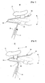
- FIG. 1 is a schematic side view of a saddle 10 for bicycles, not according to the present invention because it has no seat sliding unit.
- a metal rod having a circular cross-section and high elasticity is bent into a V-shape, as shown in FIG. 1 , to provide a guide part 30, a swiveling spring 50, and a support part 70 that are integrated with each other into a single structure.
- a seat 1 is coupled to the guide part 30.
- the guide part 30 is the metal rod which has predetermined elasticity and extends in opposite directions of a seat support frame 3 to predetermined positions.
- a rear end of the metal rod is a free end, thus allowing the guide part 30 to freely swivel up and down.
- the seat 1 is provided on the guide part 30 to be fixed to the guide part 30 or be movable in a horizontal direction.
- the seat 1 is provided at a rear portion of the guide part 30.
- the swiveling spring 50 is a bent spring that is integrally provided at a front end of the guide part 30.
- the swiveling spring 50 When a weight is applied to or removed from the seat 1, the swiveling spring 50 provides a predetermined vertical elastic force to the guide part 30, so that the rear end of the guide part 30 swivels in a vertical direction.
- the support part 70 is integrated with the swiveling spring 50 to support the swiveling spring 50, and is positioned under the guide part 30 to be spaced apart from the guide part 30 by a predetermined distance, thus allowing the guide part 30 to swivel in the vertical direction.
- a bent portion 75 having a predetermined length downwardly extends from a rear end of the support part 70 so as to be supported by the seat support frame 3.
- the guide part 30 when a weight is applied to the rear end of the guide part 30 through the seat 1, the guide part 30 downwardly swivels on the swiveling spring 50.
- the guide part 30 When the guide part 30 swivels downward to a predetermined angle, the guide part 30 upwardly swivels by a restoring force of the swiveling spring 50.
- the guide part 30 and the seat 1 elastically reciprocate in a vertical direction by a buffering force and a restoring force of the swiveling spring 50.
- the seat 1 swivel in the vertical direction, thus providing a sensation similar to that of riding a horse to the user.
- FIG. 2 is a schematic side view of a saddle 10 for bicycles, according to the first embodiment of the present invention, which is a modification of the saddle of FIG. 1 by provision of a seat sliding unit.
- a metal rod having high elasticity and a predetermined diameter is bent at predetermined positions thereof to provide a guide part 30, a swiveling spring 50, and a support part 70 which are integrated with each other into a single structure.
- a seat 1 is provided at a predetermined position of the guide part 30, which constitutes a straight-line part of the metal rod, to be movable in a horizontal direction.
- the guide part 30 extends in opposite directions of a seat support frame 3 to predetermined lengths.
- the guide part 30 is upwardly curved at a rear end thereof to provide a stopper 32. Further, a seat sliding unit 40 coupled to the seat 1 is provided at a predetermined portion of the guide part 30 to slide in a horizontal direction.
- the seat sliding unit 40 includes a body coupled to the guide part 30, and rolling wheels to allow the seat sliding unit 40 to smoothly slide along the guide part 30 forward and backward.
- the saddle 10 is constructed so that the seat 1 is installed to slide forward and backward, thus allowing the guide part 30 to be easily swiveled in a vertical direction. That is, when a user desires to swivel the guide part 30 downward, the user pushes both the seat 1 and the seat sliding unit 40 backward while sitting on the seat 1, so that the seat 1 and the seat sliding unit 40 are positioned in back of the seat support frame 3. At this time, a rear end of the guide part 30, which is a free end, swivels downward by a weight of the user.
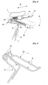
- FIG. 3 is a schematic side view a saddle 10 for bicycles, according to the second embodiment of the present invention.
- a metal rod having high elasticity is bent at predetermined positions to provide a guide part 30, a swiveling spring 50, and a support part 70 which are integrated with each other into a single structure.
- a seat sliding unit 40 coupled to a seat 1 is slidably mounted to the guide part 30.
- a return/buffer spring 60 is provided in a front of the guide part 30 to provide a restoring force and a buffering force to the seat sliding unit 40.
- a stop plate 62 is provided at a front portion of the guide part 30, and the coil-shaped return/buffer spring 60 is installed between the stop plate 62 and a front surface of the seat sliding unit 40.
- the return/buffer spring 60 allows the seat sliding unit 40 to be smoothly stopped within a predetermined range.
- the seat sliding unit 40 moves forward, the seat sliding unit 40 is pulled forward by a strong restoring force of the return/buffer spring 60, thus rapidly returning to an original position thereof.
- the saddle 10 when the seat sliding unit 40 has been completely moved forward, the seat 1 is positioned above a seat support frame 3, so that a user's weight is not put on a rear end of the guide part 30.
- the saddle 10 when the user does not want to swivel the guide part 30 in a vertical direction, the saddle 10 is used in a same manner as a conventional saddle.
- the saddle 10 when the user wants to swivel the guide part 30 in the vertical direction, that is, to feel as if the user rides a horse, the user slides the seat 1 forward and backward. Therefore, the saddle 10 according to this invention does not hinder an original function of a bicycle.
- the saddle 10 may be provided with a locking unit to lock the seat sliding unit 40 to a position, thus preventing unexpected movement of the seat sliding unit 40.
- a metal rod having high elasticity may be wound in a coil shape to provide the swiveling spring 50 at a junction between the guide part 30 and the support part 70.
- a coiled swiveling spring 50 is more smoothly swiveled in the vertical direction, as compared to a bent-shaped swiveling spring.
- various elastic materials such as a plate spring, a coil spring, a metal spring, an elastic material made of special rubber or synthetic resin, a gas shock absorber, etc. may be used as the swiveling spring 50.
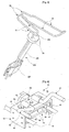
- FIGS. 4 through 8 show concrete examples of the saddle 10 for bicycles, according to the present invention.
- FIG. 4 is a perspective view to show an elastic metal rod 20 which is bent at predetermined positions thereof to provide the guide part 30, the swiveling spring 50, and the support part 70 that are integrated with each other into a single structure.
- the guide part 30, the swiveling spring 50, and the support part 70 are manufactured to have a symmetric structure while both sides of each of the guide part 30, the swiveling spring 50, and the support part 70 are spaced apart from each other by a predetermined distance, by bending the elastic metal rod 20 with a predetermined diameter and length.
- Such a construction prevents the seat 1 and the seat sliding unit 40 coupled to the guide part 30 from being rotated, and allows the swiveling spring 50 to have a sufficient elastic force, and allows the support part 70 to be firmly supported by the seat support frame 3.
- FIG. 5 shows a mounting unit 100 mounted to the support part 70.
- a disc-shaped mounting plate 102 is integrally provided on an upper end of the bent portion 75.
- An insert rod 105 having a predetermined length is mounted to a lower surface of the mounting plate 102 so as to be inserted into a hollow part of the seat support frame 3.
- a clamp 107 is mounted to a lower end of the bent portion 75, and functions to clamp the support part 70 to the seat support frame 3 while surrounding an outer circumferential surface of the seat support frame 3.
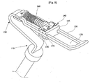
- FIG. 6 is a perspective view of the seat sliding unit 40 coupled to the guide part 30, according to the present invention.
- the seat sliding unit 40 includes a body 43 having an upper plate 41 and both side plates 42.
- a plurality of rollers 46 having guide grooves 47 to guide the guide part 30 are coupled to each other by horizontal shafts 48 to be rotatably supported by the side plates 42.
- upper and lower guide units 45 having the rollers 46 that roll along outer surfaces of upper and lower portions of the guide part 30 are installed at front and rear portions of the seat sliding unit 40, thus allowing the seat sliding unit 40 to be smoothly and reliably moved.
- any shape of seat sliding unit is possible.
- a sliding unit that has no rolling wheels may be used as the seat sliding unit 40.
- a seat clamping unit 80 is provided on the upper plate 41 of the seat sliding unit 40 to clamp the seat 1.
- the seat clamping unit 80 includes a clamping plate 82 provided on the upper plate 41 of the seat sliding unit 40, and two elastic support rods 85 which define a predetermined space between the seat sliding unit 40 and the seat 1 and provide elasticity to the seat 1.
- a lower end of each of the elastic support rods 85 is secured to the clamping plate 82, while an upper end of each of the elastic support rods 85 is secured to the lower surface of the seat 1.
- An inclined part 86 having a predetermined length is provided between the upper and lower ends of each of the elastic support rods 85.
- FIG. 7 shows the return/buffer spring 60 installed at the front portion of the seat sliding unit 40.
- the return/buffer spring 60 is a coil spring that has a predetermined length and is provided between the seat sliding unit 40 and the stop plate 62 which is vertically installed at the front portion of the guide part 30, to be extended or contracted.
- a compression spring part 63 with a predetermined length is provided on a front portion of the return/buffer spring 60, and a tension spring part 65 with a predetermined length is provided on a rear portion of the return/buffer spring 60 to be integrated with the compression spring part 63.
- the tension spring part 65 is extended backward, thus stopping the seat sliding unit 40 within a predetermined range.
- the return/buffer spring 60 is constructed so that the compression spring part and the tension spring part are integrally provided on a single coil spring, thus simplifying a structure and maximizing the moving distance of the seat sliding unit 40.
- a spring support rod 66 with a predetermined length is provided on the front surface of the seat sliding unit 40 to be inserted into a hollow part of the return/buffer spring 60, thus preventing the undesirable removal of the return/buffer spring 60.
- the spring support rod 66 is made of rubber having elasticity, thus serving as a stopper to stop the forward movement of the seat sliding unit 40.
- FIG. 8 is a sectional view to show an example of the seat 1 coupled to the guide part 30, according to the present invention.
- a locking bracket 112 is provided on the lower surface of the seat 1 to fasten the upper end of each elastic support rod 85 to the seat 1, using a fastening bolt.
- a pommel 115 is provided on the front portion of the seat 1 to be pivotable in a vertical direction. The pommel 115 functions to efficiently transmit a force from a user to the seat 1, when the user pushes the seat 1 forwardly and upwardly. However, when it is not necessary to move the seat 1 forward and backward, the pommel 115 pivots downward so as not to be projected upward.
- a ratchet wheel 118, a locking pawl 119, and a spring 114 to bias the ratchet wheel 118 downward are installed at a rotating shaft 116 of the pommel 115.
- the locking pawl 119 is pulled upward to release the pommel 115.
- the pommel 115 is pivoted upward, and then locked to a predetermined angular position by the locking pawl 119.
- the locking pawl 119 is pulled upward.
- the pommel 115 is pivoted downward by the spring 114.
- the seat 1 has a same shape as a conventional seat, so that the user can ride a bicycle without any inconvenience.
- FIG. 9 is a perspective view of a saddle for bicycles, according to the third embodiment of the present invention.
- a guide part 130, a swiveling spring 150, and a support part 170 are integrated with each other, using a plate-shaped elastic material in place of a circular metal rod.
- a guide opening 135 with a predetermined width be longitudinally provided along an central axis of the guide part 130, and a seat sliding unit 140 be installed on the guide part 130 to be movable along the guide opening 135.
- Guide channels 145 are provided on opposite sides of the seat sliding unit 140 to engage with the guide part 130, thus preventing the seat sliding unit 140 from being removed from the guide part 130.
- rolling wheels 146 are provided in the guide channels 145.
- the seat sliding unit 140 may be installed to surround the guide part 130, in place of installing the seat sliding unit 140 in the guide opening 135.
- FIG. 10 is a perspective view of a saddle for bicycles, according to the fourth embodiment of the present invention.
- a guide part 230, a swiveling spring 250, and a support part 270 are separately manufactured, and then are assembled with each other.
- the guide part 230 is a cylindrical pipe having a predetermined diameter, with a seat sliding unit 240 being fitted over the guide part 230 to slide forward and backward.
- a through hole 242 is formed at a center of the seat sliding unit 240 so that the guide part 230 passes through the through hole 242.
- Guide grooves 242 are provided on opposite sides of the through hole 242 to correspond to guide projections 233 of the guide part 230.
- a coil-shaped return/buffer spring 260 is installed between a front end of the guide part 230 and the seat sliding unit 240.
- An elastic metal rod is wound in a coil shape to provide the swiveling spring 250.
- An upper portion of the swiveling spring 250 is supported by the guide part 230, while a lower portion of the swiveling spring 250 is supported by the support part 270.
- the support part 270 is also a cylindrical pipe, and is downwardly bent at a rear portion thereof to integrally provide a bent portion 275 that is inserted into the seat support frame 3. According to the embodiment, as shown by the arrows of FIG. 10 , the guide parts 230 and the support parts 270 are coupled by the swiveling spring 250.
- the guide parts 230 are installed on opposite sides to be spaced apart from each other by a predetermined interval.
- the support parts 270 are installed on opposite sides to be spaced apart from each other by a predetermined interval.
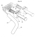
- FIG. 11 is a perspective view of a saddle for bicycles, according to the fifth embodiment of the present invention.
- the saddle of the sixth embodiment is constructed so that return/buffer springs 60 and 360 are respectively installed in the front and back of the seat sliding unit 40 coupled to the guide part 30.
- the return/buffer spring 60 installed in the front of the seat sliding unit 40 is almost compression spring part, thus providing a strong restoring force when the seat sliding unit 40 moves forward.
- the return/buffer spring 360 installed in the back of the seat sliding unit 40 is almost tension spring part, thus allowing the seat sliding unit 40 to be smoothly stopped, when the seat sliding unit 40 moves backward.
- the return/buffer spring 360 is compressed by the seat sliding unit 40 which is moved backward, thus providing an additional elastic restoring force to the seat sliding unit 40.
- the return/buffer springs 60 and 360 are respectively provided in the front and back of the seat sliding unit 40, thus increasing the buffering force and restoring force.
- FIG. 12 an existing fixed-type saddle is detached from the seat support frame 3, and then the saddle 10 of this invention is installed on the seat support frame 3, through a same method as that of installing the fixed-type saddle.
- the insert rod 105 mounted to the lower surface of the mounting plate 102 is inserted into the seat support frame 3, and then is secured to a proper height according to a body type of a user.
- the bent portion 75 is clamped to the seat support frame 3 using the clamp 107 so that the bent portion 75 is not rotated leftward and rightward.
- the seat 1 When a user desires to use only the original function of a bicycle, the seat 1 is forward pulled to the maximum so that the seat 1 is positioned in front of the seat support frame 3. In this case, the user can ride the bicycle in a same manner as the conventional bicycle. Meanwhile, in the case of having the return/buffer spring 60 of this invention, the seat 1 is biased to be always positioned in front of the seat support frame 3, so that it is unnecessary for the user to pull the seat 1. Further, in the case of having the locking unit, it is preferable that the seat 1 be locked to a predetermined position by the locking unit, thus preventing the seat 1 from being moved backward.
- the locking unit is unlocked. Subsequently, the user pushes the seat 1 backward while sitting on the seat 1. When the seat 1 has been sufficiently moved backward, the user pushes the seat 1 forward while lining the user's rear above the seat 1. Next, when the seat 1 has been sufficiently moved forward, the user pushes the seat 1 backward while sitting on the seat 1.
- the seat 1 when the user repeatedly moves the seat 1 forward and backward, and simultaneously adjusts the user's weight acting on the seat 1, the seat 1 is swiveled vertically by the restoring force and the buffering force of the swiveling spring 50 and the return/buffer spring 60, thus providing the sensation similar to that of riding a horse to the user.
- the bicycle incorporating the saddle of this invention develops abdominal and arm muscles, in addition to efficiently exercising the lower part of the user's body in the same manner as the conventional bicycle. Further, the bicycle incorporating the saddle strengthens pelvic muscles and a sphincter, thus preventing urinary incontinence in women, and increasing stamina of men and promoting health.
- the present invention provides a saddle for bicycles, which can be used without changing a structure of a conventional bicycle including a stationary bicycle, and has a vertical swiveling function and a horizontal sliding function, thus providing a sensation similar to that of riding a horse to a user while the user rides a bicycle.
- a user moves a seat forward and backward while sitting on the seat, and simultaneously, repeatedly sits down on the seat and lifts the user's rear above the seat to adjust weight acting on the seat, thus preventing dysuria and a sexual dysfunction due to a sensation of pressure on the perineal region when pedaling a bicycle, different from a conventional fixed-type saddle.
- the saddle of this invention exercises the upper part of the body including the pelvis and torso as well as the lower part of the body and the abdominal region, thus exercising every part of the body.
- a bicycle equipped with the saddle exercises the exercise of the whole body, so that a range of motion is increased in comparison with the conventional bicycle.
Landscapes
- Engineering & Computer Science (AREA)
- Mechanical Engineering (AREA)
- Rehabilitation Tools (AREA)
- Motorcycle And Bicycle Frame (AREA)
- Seats For Vehicles (AREA)
- Transition And Organic Metals Composition Catalysts For Addition Polymerization (AREA)
- Chairs Characterized By Structure (AREA)
Claims (17)
- Ein Sattel (10), der mit einem Sitztragrahmen (3) eines Fahrrads gekoppelt ist, mit:einer Sitzgleiteinheit (40), die an einer unteren Fläche eines Sitzes (1) vorgesehen ist, um den Sitz (1) vorwärts und rückwärts zu verschieben, wenn sich ein Benutzer vorwärts und rückwärts bewegt, während er auf dem Sitz (1) sitzt;einem Führungsteil (30) mit einer festgelegten Länge, welches die Sitzgleiteinheit (40) abstützt, um eine horizontale Bewegung der Sitzgleiteinheit (40) innerhalb eines festgelegten Bereiches zu führen, wobei ein freies Ende an einem hinteren Ende des Führungsteils (30) vorgesehen ist, um es dem Führungsteil (30) zu gestatten, vertikal verschwenkt zu werden, wenn ein Gewicht auf das Führungsteil (30) aufgebracht oder von diesem entfernt wird;einer Schwenkfeder (50), die an einem vorderen Ende des Führungsteils (30) vorgesehen ist, um eine vertikale elastische Kraft auf das Führungsteil (30) auszuüben; undeinem Stützteil (70), um die Schwenkfeder (50) abzustützen, und mit einem nach unten gebogenen Abschnitt (75), um den Stützteil (70) mit dem Sitztragrahmen (3) zu koppeln.
- Der Sattel nach Anspruch 1, wobei der Führungsteil (30) sich um festgelegte Längen in entgegengesetzten Richtungen des Sitztragrahmens (3) erstreckt, wobei das freie Ende an dem hinteren Ende des Führungsteils (30) vorgesehen ist und wobei die Schwenkfeder (50) an dem vorderen Ende des Führungsteils (30) vorgesehen ist.
- Der Sattel nach Anspruch 2, wobei die Schwenkfeder (50) so hergestellt ist, dass sie eine vertikale elastische Kraft aufweist, indem ein stangen- oder plattenförmiges elastisches Material zu einer V-Form gebogen wird.
- Der Sattel nach Anspruch 1 oder 2, wobei die Schwenkfeder (50) so hergestellt ist, dass sie die vertikale elastische Kraft aufweist, indem ein stangenförmiges elastisches Material zu einer Spulenform gewickelt wird.
- Der Sattel nach Anspruch 1, wobei das Stützteil (70) mit der Schwenkfeder (50) integriert ist, um die Schwenkfeder (50) abzustützen, und unter dem Führungsteil (30) angeordnet ist, um einen festgelegten Abstand von dem Führungsteil (30) aufzuweisen, so dass das Führungsteil (30) vertikal verschwenkt werden kann, wobei das Stützteil (70) einen nach unten gebogenen Abschnitt (75) mit einer festgelegten Länge aufweist, um mit Hilfe des nach unten gebogenen Abschnitts (75) mit dem Sitztragrahmen (3) gekoppelt zu werden.
- Der Sattel nach Anspruch 5, wobei das Stützteil (70) sich um eine festgelegte Länge von dem Sitztragrahmen (3) nach vorne erstreckt.
- Der Sattel nach Anspruch 1, außerdem mit einer Rückführ-/ Pufferfeder (60), die an einem vorderen Abschnitt des Führ-ungsteils (30) vorgesehen ist, um eine Pufferkraft und eine Rückführkraft auf die Sitzgleiteinheit (40) auszuüben, wenn sich die Sitzgleiteinheit (40) vorwärts und rückwärts bewegt.
- Der Sattel nach Anspruch 7, wobei die Rückführ-/ Pufferfeder (60) eine Spulenfeder ist, die einen Druckfederteil (63) und einen Zugfederteil (65) aufweist, die jeweils eine festgelegte Länge aufweisen und miteinander zu einer einzigen Struktur zusammen gefügt sind.
- Der Sattel nach Anspruch 1, wobei
der Führungsteil (30) sich um festgelegte Längen in entgegengesetzten Richtungen des Sitztragrahmens (3) erstreckt, so dass der Sitz (1) auf dem Führungsteil (30) angebracht ist;
die Schwenkfeder (50) integral an dem vorderen Ende des Führungsteils (30) vorgesehen ist, um durch ein Gewicht, das auf dem Sitz (1) aufgebracht oder von diesem entfernt wird, das hintere Ende des Führungsteils (30) vertikal zu verschwenken;
der Stützteil (70) mit der Schwenkfeder integriert ist, um die Schwenkfeder (50) abzustützen, und unter dem Führungsteil (30) so angeordnet ist, dass er einen festgelegten Abstand von dem Führungsteil (30) aufweist, so dass das Führungsteil (30) vertikal verschwenkt werden kann, wobei der gebogene Abschnitt (75) eine festgelegte Länge aufweist, um mit Hilfe des gebogenen Abschnitts (75) an den Sitztragrahmen (3) gekoppelt zu werden; und
die Sitzgleiteinheit (40) vorgesehen ist, um sich vorwärts und rückwärts entlang des Führungsteils (30) zu bewegen; und außerdem mit
einer Rückführ-/ Pufferfeder (60), die zwischen dem vorderen Ende des Führungsteils (30) und der Sitzgleiteinheit (40) vorgesehen ist, um eine Pufferkraft und eine Rückführkraft auf die Sitzgleiteinheit (40) auszuüben, wenn sich die Sitzgleiteinheit (40) vorwärts und rückwärts bewegt. - Der Sattel nach Anspruch 9, wobei der Führungsteil (30), die Schwenkfeder (50) und der Stützteil (70) so hergestellt sind, dass sie einen symmetrischen Aufbau haben, wobei beiden Seiten des Führungsteils (30), der Schwenkfeder (50) und des Stützteils (70) voneinander einen festgelegten Abstand aufweisen, indem eine elastische Metallstange mit einem festgelegten Durchmesser und Länge gebogen wird.
- Der Sattel nach Anspruch 9 oder 10, außerdem mit einer Befestigungsplatte (102), die an einem oberen Ende des gebogenen Abschnitts (75) des Stützteils (70) vorgesehen ist, wobei eine Einsetzstange (105) mit einer festgelegten Länge an der Befestigungsplatte (102) angebracht ist, um in einen hohlen Teil des Sitzstützrahmens (3) eingesetzt zu werden.
- Der Sattel nach Anspruch 9 oder 10, wobei die Sitzgleiteinheit (40) folgende Elemente aufweist:einen Körper (43), der eine obere Platte (41) und Seitenplatten (42) umfasst; und eine Mehrzahl von Walzen (46), die jeweils eine Führungsnut (47) aufweisen, um den Führungsteil (30) zu führen, wobei die Walzen (46) miteinander durch eine horizontale Welle (48) so gekoppelt werden, dass sie drehbar durch die Seitenplatten (42) gehalten werden.
- Der Sattel nach Anspruch 12, außerdem mit einer Klemmplatte (82), die an der oberen Platte (41) der Sitzgleiteinheit (40) vorgesehen ist, um die beiden elastischen Stützstangen (85) zu klemmen, wobei die elastischen Stützstangen (85) einen festgelegten Abstand zwischen der Sitzgleiteinheit (40) und dem Sitz definieren und eine elastische Kraft auf den Sitz (1) ausüben.
- Der Sattel nach Anspruch 9, außerdem mit einem Knauf (115), der so an einem vorderen Abschnitt des Sitzes (1) vorgesehen ist, dass er vertikal schwenkt.
- Der Sattel nach Anspruch 9, wobei der Führungsteil (130), die Schwenkfeder (150) und der Stützteil (170) durch Biegen eines plattenförmigen elastischen Materials hergestellt werden, wobei eine Führungsöffnung (135), die eine festgelegte Breite aufweist, in Längsrichtung entlang einer zentralen Achse des Führungsteils (130) vorgesehen ist, und wobei die Sitzgleiteinheit (140) so in der Führungsöffnung (135) angebracht ist, dass sie sich vorwärts und rückwärts bewegt.
- Der Sattel nach Anspruch 9, wobei der Führungsteil (230) ein zylindrisches Rohr ist, das als eine abtrennbare Komponente hergestellt ist, und wobei die Sitzgleiteinheit (240) in ihrer Mitte eine Durchgangsöffnung (242) aufweist und gleitend auf den Führungsteil (230) gesetzt ist.
- Der Sattel nach Anspruch 9, wobei zwischen der Sitzgleiteinheit (40) und einem hinteren Ende des Führungsteils (30) eine zweite Rückführ-/ Pufferfeder (360) angebracht ist, wodurch die Pufferkraft und die Rückführkraft auf die Sitzgleiteinheit (40) ausgeübt werden, wenn sich die Sitzgleiteinheit (40) vorwärts und rückwärts bewegt.
Applications Claiming Priority (2)
| Application Number | Priority Date | Filing Date | Title |
|---|---|---|---|
| KR1020030085141A KR100678606B1 (ko) | 2003-11-27 | 2003-11-27 | 자전거용 승마형 안장 |
| PCT/KR2004/003037 WO2005051751A1 (en) | 2003-11-27 | 2004-11-24 | Saddle for bicycle |
Publications (3)
| Publication Number | Publication Date |
|---|---|
| EP1699681A1 EP1699681A1 (de) | 2006-09-13 |
| EP1699681A4 EP1699681A4 (de) | 2008-05-07 |
| EP1699681B1 true EP1699681B1 (de) | 2010-06-02 |
Family
ID=36808408
Family Applications (1)
| Application Number | Title | Priority Date | Filing Date |
|---|---|---|---|
| EP04819498A Expired - Lifetime EP1699681B1 (de) | 2003-11-27 | 2004-11-24 | Sattel für fahrrad |
Country Status (8)
| Country | Link |
|---|---|
| EP (1) | EP1699681B1 (de) |
| JP (1) | JP4793994B2 (de) |
| KR (1) | KR100678606B1 (de) |
| CN (1) | CN100404354C (de) |
| AT (1) | ATE469815T1 (de) |
| DE (1) | DE602004027541D1 (de) |
| ES (1) | ES2347153T3 (de) |
| WO (1) | WO2005051751A1 (de) |
Cited By (1)
| Publication number | Priority date | Publication date | Assignee | Title |
|---|---|---|---|---|
| US12064156B2 (en) | 2023-01-09 | 2024-08-20 | John F. Krumme | Dynamic compression fixation devices |
Families Citing this family (9)
| Publication number | Priority date | Publication date | Assignee | Title |
|---|---|---|---|---|
| KR101167029B1 (ko) * | 2012-03-27 | 2012-07-24 | 김춘추 | 이동식 안장을 구비하는 자전거 |
| KR101407276B1 (ko) | 2012-10-30 | 2014-06-16 | 이예라 | 자전거의 안장 완충장치 |
| US10293876B2 (en) * | 2014-09-23 | 2019-05-21 | Bombardier Recreational Products Inc. | Removable backrest for a vehicle |
| KR101599637B1 (ko) | 2014-10-24 | 2016-03-03 | 김인구 | 헬스형 승마자전거 |
| KR101599638B1 (ko) | 2014-10-24 | 2016-03-03 | 김인구 | 헬스형 승마자전거의 안장 |
| KR101599639B1 (ko) | 2014-10-24 | 2016-03-03 | 김인구 | 헬스형 승마자전거의 핸들바 |
| CN106943276A (zh) * | 2017-03-15 | 2017-07-14 | 深圳市奇诺动力科技有限公司 | 动力外骨骼 |
| KR102480435B1 (ko) * | 2021-04-28 | 2022-12-22 | 박수신 | 인체공학적 자전거 안장 |
| TWM662741U (zh) * | 2024-07-01 | 2024-11-11 | 羅伯特 倪尼 | 可前後位置調節的載具座墊總成 |
Family Cites Families (16)
| Publication number | Priority date | Publication date | Assignee | Title |
|---|---|---|---|---|
| DE405358C (de) * | 1924-01-19 | 1924-10-31 | Buchloh & Renkhoff | Kippbarer Gleitsattel fuer Fahrraeder |
| JPS5568685U (de) | 1978-11-02 | 1980-05-12 | ||
| JPS56146685U (de) | 1980-04-02 | 1981-11-05 | ||
| KR840003075A (ko) * | 1982-12-16 | 1984-08-13 | 미쓰다 가쓰시게 | 표시장치(表示製置)의 제어 방법 |
| JPH0618867Y2 (ja) * | 1988-04-12 | 1994-05-18 | マエダ工業株式会社 | 自転車のサドルの支持構造 |
| JP3374249B2 (ja) * | 1991-12-27 | 2003-02-04 | トキコ株式会社 | サドル支持装置 |
| JPH0632282U (ja) * | 1992-10-07 | 1994-04-26 | 株式会社坂本製作所 | 自転車のサドル緩衝装置 |
| CN1089557A (zh) * | 1993-01-07 | 1994-07-20 | 姚玉龙 | 自行车移动鞍座 |
| CN2165068Y (zh) * | 1993-03-29 | 1994-05-18 | 郭道宾 | 鞍座的弹性支承 |
| JPH08169375A (ja) * | 1994-12-17 | 1996-07-02 | Yuji Baba | 自転車におけるサドル取付装置 |
| NO300168B1 (no) | 1995-06-01 | 1997-04-21 | Hals Lauritzen As | Fjærende seteholdermontasje for tohjulet kjöretöy |
| WO1997022512A1 (de) * | 1995-12-19 | 1997-06-26 | Spengle Hochleistungskunststofftechnik Ges.Mbh | Sattelgestell |
| JP3026929U (ja) * | 1996-01-18 | 1996-07-30 | 春夫 平湯 | 自転車用スライディングサドル |
| CN2331571Y (zh) * | 1998-02-20 | 1999-08-04 | 罗宝红 | 自行车车座 |
| CN2387013Y (zh) * | 1999-09-16 | 2000-07-12 | 何志成 | 电动自行车旋转式座管结构 |
| KR200299481Y1 (ko) * | 2002-07-13 | 2003-01-03 | 박천우 | 승마 겸용 헬스 자전거 |
-
2003
- 2003-11-27 KR KR1020030085141A patent/KR100678606B1/ko not_active Expired - Fee Related
-
2004
- 2004-11-24 WO PCT/KR2004/003037 patent/WO2005051751A1/en not_active Ceased
- 2004-11-24 CN CNB2004800349835A patent/CN100404354C/zh not_active Expired - Fee Related
- 2004-11-24 ES ES04819498T patent/ES2347153T3/es not_active Expired - Lifetime
- 2004-11-24 DE DE602004027541T patent/DE602004027541D1/de not_active Expired - Lifetime
- 2004-11-24 AT AT04819498T patent/ATE469815T1/de not_active IP Right Cessation
- 2004-11-24 EP EP04819498A patent/EP1699681B1/de not_active Expired - Lifetime
- 2004-11-24 JP JP2006541035A patent/JP4793994B2/ja not_active Expired - Fee Related
Cited By (1)
| Publication number | Priority date | Publication date | Assignee | Title |
|---|---|---|---|---|
| US12064156B2 (en) | 2023-01-09 | 2024-08-20 | John F. Krumme | Dynamic compression fixation devices |
Also Published As
| Publication number | Publication date |
|---|---|
| EP1699681A4 (de) | 2008-05-07 |
| EP1699681A1 (de) | 2006-09-13 |
| JP2007521998A (ja) | 2007-08-09 |
| WO2005051751A8 (en) | 2005-11-03 |
| JP4793994B2 (ja) | 2011-10-12 |
| DE602004027541D1 (de) | 2010-07-15 |
| KR20050051369A (ko) | 2005-06-01 |
| KR100678606B1 (ko) | 2007-02-05 |
| ATE469815T1 (de) | 2010-06-15 |
| CN1886292A (zh) | 2006-12-27 |
| WO2005051751A1 (en) | 2005-06-09 |
| CN100404354C (zh) | 2008-07-23 |
| ES2347153T3 (es) | 2010-10-26 |
Similar Documents
| Publication | Publication Date | Title |
|---|---|---|
| US7455356B2 (en) | Saddle for bicycles | |
| US5873626A (en) | Bicycle seat | |
| EP1699681B1 (de) | Sattel für fahrrad | |
| US7762931B2 (en) | Seat for cardio-fitness equipment | |
| US10399625B2 (en) | Tilt angle adjusting apparatus for bicycle saddle | |
| US4768775A (en) | Combination rowing machine and chest exerciser | |
| US20030008753A1 (en) | Magnets adjusting device for bike exercisers | |
| US20200282256A1 (en) | Foot supports and handlebar with fit enhancement features for an exercise machine | |
| US20140187396A1 (en) | Reformer exercise apparatus | |
| US4909522A (en) | Non-mechanical bicycle seat attachment for thrust support | |
| CN210409377U (zh) | 固定自行车式运动器 | |
| US20080129008A1 (en) | Arm and Leg Powered Vehicle | |
| EP0569518B1 (de) | Stossabsorbierender leitstangenzusammenbau | |
| NL2033110B1 (en) | Additional seat structure for electric bicycles | |
| US20090236822A1 (en) | Bicycle rider seat brace | |
| CN201354112Y (zh) | 一种自行车鞍座 | |
| CN111514523B (zh) | 运动器材 | |
| US20250249334A1 (en) | Exercise bike with side-to-side motion mechanism | |
| US4811945A (en) | Unobstructed adjustable V-frame exercycle | |
| KR200350070Y1 (ko) | 자전거용 승마형 안장 | |
| US20030050155A1 (en) | Body exerciser | |
| CN212974020U (zh) | 一种多功能健身车 | |
| US20030006082A1 (en) | Passenger safety handlebar | |
| CN221084544U (zh) | 一种卧式健身车的扩展结构及卧式健身车训练系统 | |
| CN219963863U (zh) | 一种健身运动单车 |
Legal Events
| Date | Code | Title | Description |
|---|---|---|---|
| PUAI | Public reference made under article 153(3) epc to a published international application that has entered the european phase |
Free format text: ORIGINAL CODE: 0009012 |
|
| 17P | Request for examination filed |
Effective date: 20060626 |
|
| AK | Designated contracting states |
Kind code of ref document: A1 Designated state(s): AT BE BG CH CY CZ DE DK EE ES FI FR GB GR HU IE IS IT LI LU MC NL PL PT RO SE SI SK TR |
|
| DAX | Request for extension of the european patent (deleted) | ||
| A4 | Supplementary search report drawn up and despatched |
Effective date: 20080404 |
|
| 17Q | First examination report despatched |
Effective date: 20080716 |
|
| GRAP | Despatch of communication of intention to grant a patent |
Free format text: ORIGINAL CODE: EPIDOSNIGR1 |
|
| GRAS | Grant fee paid |
Free format text: ORIGINAL CODE: EPIDOSNIGR3 |
|
| GRAA | (expected) grant |
Free format text: ORIGINAL CODE: 0009210 |
|
| AK | Designated contracting states |
Kind code of ref document: B1 Designated state(s): AT BE BG CH CY CZ DE DK EE ES FI FR GB GR HU IE IS IT LI LU MC NL PL PT RO SE SI SK TR |
|
| REG | Reference to a national code |
Ref country code: GB Ref legal event code: FG4D |
|
| REG | Reference to a national code |
Ref country code: CH Ref legal event code: EP |
|
| REG | Reference to a national code |
Ref country code: IE Ref legal event code: FG4D |
|
| REF | Corresponds to: |
Ref document number: 602004027541 Country of ref document: DE Date of ref document: 20100715 Kind code of ref document: P |
|
| REG | Reference to a national code |
Ref country code: NL Ref legal event code: T3 |
|
| REG | Reference to a national code |
Ref country code: SE Ref legal event code: TRGR |
|
| REG | Reference to a national code |
Ref country code: ES Ref legal event code: FG2A Ref document number: 2347153 Country of ref document: ES Kind code of ref document: T3 |
|
| PG25 | Lapsed in a contracting state [announced via postgrant information from national office to epo] |
Ref country code: AT Free format text: LAPSE BECAUSE OF FAILURE TO SUBMIT A TRANSLATION OF THE DESCRIPTION OR TO PAY THE FEE WITHIN THE PRESCRIBED TIME-LIMIT Effective date: 20100602 Ref country code: SI Free format text: LAPSE BECAUSE OF FAILURE TO SUBMIT A TRANSLATION OF THE DESCRIPTION OR TO PAY THE FEE WITHIN THE PRESCRIBED TIME-LIMIT Effective date: 20100602 |
|
| PG25 | Lapsed in a contracting state [announced via postgrant information from national office to epo] |
Ref country code: CY Free format text: LAPSE BECAUSE OF FAILURE TO SUBMIT A TRANSLATION OF THE DESCRIPTION OR TO PAY THE FEE WITHIN THE PRESCRIBED TIME-LIMIT Effective date: 20100602 Ref country code: PL Free format text: LAPSE BECAUSE OF FAILURE TO SUBMIT A TRANSLATION OF THE DESCRIPTION OR TO PAY THE FEE WITHIN THE PRESCRIBED TIME-LIMIT Effective date: 20100602 Ref country code: GR Free format text: LAPSE BECAUSE OF FAILURE TO SUBMIT A TRANSLATION OF THE DESCRIPTION OR TO PAY THE FEE WITHIN THE PRESCRIBED TIME-LIMIT Effective date: 20100903 |
|
| PG25 | Lapsed in a contracting state [announced via postgrant information from national office to epo] |
Ref country code: EE Free format text: LAPSE BECAUSE OF FAILURE TO SUBMIT A TRANSLATION OF THE DESCRIPTION OR TO PAY THE FEE WITHIN THE PRESCRIBED TIME-LIMIT Effective date: 20100602 |
|
| PG25 | Lapsed in a contracting state [announced via postgrant information from national office to epo] |
Ref country code: SK Free format text: LAPSE BECAUSE OF FAILURE TO SUBMIT A TRANSLATION OF THE DESCRIPTION OR TO PAY THE FEE WITHIN THE PRESCRIBED TIME-LIMIT Effective date: 20100602 Ref country code: RO Free format text: LAPSE BECAUSE OF FAILURE TO SUBMIT A TRANSLATION OF THE DESCRIPTION OR TO PAY THE FEE WITHIN THE PRESCRIBED TIME-LIMIT Effective date: 20100602 Ref country code: PT Free format text: LAPSE BECAUSE OF FAILURE TO SUBMIT A TRANSLATION OF THE DESCRIPTION OR TO PAY THE FEE WITHIN THE PRESCRIBED TIME-LIMIT Effective date: 20101004 Ref country code: IS Free format text: LAPSE BECAUSE OF FAILURE TO SUBMIT A TRANSLATION OF THE DESCRIPTION OR TO PAY THE FEE WITHIN THE PRESCRIBED TIME-LIMIT Effective date: 20101002 Ref country code: CZ Free format text: LAPSE BECAUSE OF FAILURE TO SUBMIT A TRANSLATION OF THE DESCRIPTION OR TO PAY THE FEE WITHIN THE PRESCRIBED TIME-LIMIT Effective date: 20100602 Ref country code: BE Free format text: LAPSE BECAUSE OF FAILURE TO SUBMIT A TRANSLATION OF THE DESCRIPTION OR TO PAY THE FEE WITHIN THE PRESCRIBED TIME-LIMIT Effective date: 20100602 |
|
| PGFP | Annual fee paid to national office [announced via postgrant information from national office to epo] |
Ref country code: GB Payment date: 20101130 Year of fee payment: 7 Ref country code: IT Payment date: 20101129 Year of fee payment: 7 |
|
| PLBE | No opposition filed within time limit |
Free format text: ORIGINAL CODE: 0009261 |
|
| STAA | Information on the status of an ep patent application or granted ep patent |
Free format text: STATUS: NO OPPOSITION FILED WITHIN TIME LIMIT |
|
| PG25 | Lapsed in a contracting state [announced via postgrant information from national office to epo] |
Ref country code: DK Free format text: LAPSE BECAUSE OF FAILURE TO SUBMIT A TRANSLATION OF THE DESCRIPTION OR TO PAY THE FEE WITHIN THE PRESCRIBED TIME-LIMIT Effective date: 20100602 |
|
| 26N | No opposition filed |
Effective date: 20110303 |
|
| REG | Reference to a national code |
Ref country code: DE Ref legal event code: R097 Ref document number: 602004027541 Country of ref document: DE Effective date: 20110302 |
|
| PG25 | Lapsed in a contracting state [announced via postgrant information from national office to epo] |
Ref country code: MC Free format text: LAPSE BECAUSE OF NON-PAYMENT OF DUE FEES Effective date: 20101130 |
|
| REG | Reference to a national code |
Ref country code: CH Ref legal event code: PL |
|
| PG25 | Lapsed in a contracting state [announced via postgrant information from national office to epo] |
Ref country code: LI Free format text: LAPSE BECAUSE OF NON-PAYMENT OF DUE FEES Effective date: 20101130 Ref country code: CH Free format text: LAPSE BECAUSE OF NON-PAYMENT OF DUE FEES Effective date: 20101130 |
|
| PG25 | Lapsed in a contracting state [announced via postgrant information from national office to epo] |
Ref country code: IE Free format text: LAPSE BECAUSE OF NON-PAYMENT OF DUE FEES Effective date: 20101124 |
|
| PGFP | Annual fee paid to national office [announced via postgrant information from national office to epo] |
Ref country code: ES Payment date: 20111122 Year of fee payment: 8 Ref country code: FI Payment date: 20111116 Year of fee payment: 8 Ref country code: SE Payment date: 20111124 Year of fee payment: 8 Ref country code: NL Payment date: 20111128 Year of fee payment: 8 |
|
| PG25 | Lapsed in a contracting state [announced via postgrant information from national office to epo] |
Ref country code: HU Free format text: LAPSE BECAUSE OF FAILURE TO SUBMIT A TRANSLATION OF THE DESCRIPTION OR TO PAY THE FEE WITHIN THE PRESCRIBED TIME-LIMIT Effective date: 20101203 Ref country code: LU Free format text: LAPSE BECAUSE OF NON-PAYMENT OF DUE FEES Effective date: 20101124 Ref country code: BG Free format text: LAPSE BECAUSE OF FAILURE TO SUBMIT A TRANSLATION OF THE DESCRIPTION OR TO PAY THE FEE WITHIN THE PRESCRIBED TIME-LIMIT Effective date: 20100602 |
|
| PG25 | Lapsed in a contracting state [announced via postgrant information from national office to epo] |
Ref country code: TR Free format text: LAPSE BECAUSE OF FAILURE TO SUBMIT A TRANSLATION OF THE DESCRIPTION OR TO PAY THE FEE WITHIN THE PRESCRIBED TIME-LIMIT Effective date: 20100602 |
|
| PGFP | Annual fee paid to national office [announced via postgrant information from national office to epo] |
Ref country code: DE Payment date: 20121203 Year of fee payment: 9 |
|
| PGFP | Annual fee paid to national office [announced via postgrant information from national office to epo] |
Ref country code: FR Payment date: 20121220 Year of fee payment: 9 |
|
| REG | Reference to a national code |
Ref country code: NL Ref legal event code: V1 Effective date: 20130601 |
|
| GBPC | Gb: european patent ceased through non-payment of renewal fee |
Effective date: 20121124 |
|
| PG25 | Lapsed in a contracting state [announced via postgrant information from national office to epo] |
Ref country code: SE Free format text: LAPSE BECAUSE OF NON-PAYMENT OF DUE FEES Effective date: 20121125 |
|
| PG25 | Lapsed in a contracting state [announced via postgrant information from national office to epo] |
Ref country code: IT Free format text: LAPSE BECAUSE OF NON-PAYMENT OF DUE FEES Effective date: 20121124 Ref country code: NL Free format text: LAPSE BECAUSE OF NON-PAYMENT OF DUE FEES Effective date: 20130601 Ref country code: FI Free format text: LAPSE BECAUSE OF NON-PAYMENT OF DUE FEES Effective date: 20121124 |
|
| PG25 | Lapsed in a contracting state [announced via postgrant information from national office to epo] |
Ref country code: BG Free format text: LAPSE BECAUSE OF FAILURE TO SUBMIT A TRANSLATION OF THE DESCRIPTION OR TO PAY THE FEE WITHIN THE PRESCRIBED TIME-LIMIT Effective date: 20100902 |
|
| PG25 | Lapsed in a contracting state [announced via postgrant information from national office to epo] |
Ref country code: GB Free format text: LAPSE BECAUSE OF NON-PAYMENT OF DUE FEES Effective date: 20121124 |
|
| REG | Reference to a national code |
Ref country code: ES Ref legal event code: FD2A Effective date: 20140305 |
|
| PG25 | Lapsed in a contracting state [announced via postgrant information from national office to epo] |
Ref country code: ES Free format text: LAPSE BECAUSE OF NON-PAYMENT OF DUE FEES Effective date: 20121125 |
|
| REG | Reference to a national code |
Ref country code: FR Ref legal event code: ST Effective date: 20140731 |
|
| PG25 | Lapsed in a contracting state [announced via postgrant information from national office to epo] |
Ref country code: DE Free format text: LAPSE BECAUSE OF NON-PAYMENT OF DUE FEES Effective date: 20140603 |
|
| REG | Reference to a national code |
Ref country code: DE Ref legal event code: R119 Ref document number: 602004027541 Country of ref document: DE Effective date: 20140603 |
|
| PG25 | Lapsed in a contracting state [announced via postgrant information from national office to epo] |
Ref country code: FR Free format text: LAPSE BECAUSE OF NON-PAYMENT OF DUE FEES Effective date: 20131202 |