EP1700496B1 - Procede et dispositif permettant de determiner l'emplacement d'unites en utilisant des groupes subdivises d'unites - Google Patents
Procede et dispositif permettant de determiner l'emplacement d'unites en utilisant des groupes subdivises d'unites Download PDFInfo
- Publication number
- EP1700496B1 EP1700496B1 EP04814431A EP04814431A EP1700496B1 EP 1700496 B1 EP1700496 B1 EP 1700496B1 EP 04814431 A EP04814431 A EP 04814431A EP 04814431 A EP04814431 A EP 04814431A EP 1700496 B1 EP1700496 B1 EP 1700496B1
- Authority
- EP
- European Patent Office
- Prior art keywords
- units
- sub
- net
- location
- range
- Prior art date
- Legal status (The legal status is an assumption and is not a legal conclusion. Google has not performed a legal analysis and makes no representation as to the accuracy of the status listed.)
- Expired - Lifetime
Links
- 238000000034 method Methods 0.000 title claims abstract description 30
- 238000004891 communication Methods 0.000 claims description 52
- 238000005259 measurement Methods 0.000 claims description 22
- 235000008694 Humulus lupulus Nutrition 0.000 claims description 9
- 230000008867 communication pathway Effects 0.000 claims description 5
- 238000012544 monitoring process Methods 0.000 claims description 4
- 230000001413 cellular effect Effects 0.000 claims description 3
- 230000037361 pathway Effects 0.000 claims description 3
- 238000010295 mobile communication Methods 0.000 claims 2
- 230000010363 phase shift Effects 0.000 claims 2
- 238000010586 diagram Methods 0.000 description 17
- 238000012545 processing Methods 0.000 description 8
- 238000013459 approach Methods 0.000 description 6
- 230000006870 function Effects 0.000 description 6
- 230000006872 improvement Effects 0.000 description 4
- 230000001419 dependent effect Effects 0.000 description 3
- 238000004364 calculation method Methods 0.000 description 2
- 238000005265 energy consumption Methods 0.000 description 2
- 230000015654 memory Effects 0.000 description 2
- 230000008569 process Effects 0.000 description 2
- 208000036357 GUCY2D-related recessive retinopathy Diseases 0.000 description 1
- 238000007476 Maximum Likelihood Methods 0.000 description 1
- 230000002411 adverse Effects 0.000 description 1
- 230000008859 change Effects 0.000 description 1
- 230000001186 cumulative effect Effects 0.000 description 1
- 230000001934 delay Effects 0.000 description 1
- 238000001514 detection method Methods 0.000 description 1
- 238000002474 experimental method Methods 0.000 description 1
- 238000012986 modification Methods 0.000 description 1
- 230000004048 modification Effects 0.000 description 1
- 230000003287 optical effect Effects 0.000 description 1
- 239000004065 semiconductor Substances 0.000 description 1
- 239000007787 solid Substances 0.000 description 1
- 238000006467 substitution reaction Methods 0.000 description 1
Images


Classifications
-
- G—PHYSICS
- G01—MEASURING; TESTING
- G01S—RADIO DIRECTION-FINDING; RADIO NAVIGATION; DETERMINING DISTANCE OR VELOCITY BY USE OF RADIO WAVES; LOCATING OR PRESENCE-DETECTING BY USE OF THE REFLECTION OR RERADIATION OF RADIO WAVES; ANALOGOUS ARRANGEMENTS USING OTHER WAVES
- G01S5/00—Position-fixing by co-ordinating two or more direction or position line determinations; Position-fixing by co-ordinating two or more distance determinations
- G01S5/02—Position-fixing by co-ordinating two or more direction or position line determinations; Position-fixing by co-ordinating two or more distance determinations using radio waves
- G01S5/0284—Relative positioning
- G01S5/0289—Relative positioning of multiple transceivers, e.g. in ad hoc networks
Definitions
- the present invention relates generally to the determining a location of a plurality of units operating within a network, and more particularly, to the distribution of the processing associated with the determination through a sub-division of the plurality of units into a plurality of sub-nets, which are adapted to separately evaluate the location of the plurality of units in each of the corresponding sub-nets.
- an location estimation can be determined based upon a known relationship of a group of units relative to one another, as well as the relationship between at least some of the units in the group relative to one or more reference units.
- an iterative approach may exist for estimating a location for a plurality of units forming a multi-hop network.
- Patwari et al. U.S. Patent No. 6,473,038 .
- the various distance/range information is gathered in a centralized location, where a set of locations are initially estimated, and a corresponding error value is determined for the set of locations.
- the location estimates will be iteratively adjusted until the corresponding error value is minimized.
- an error value will be based upon the accumulated differences associated with the distance between units relative to the estimated locations, and the measured distance between units using one or more measured ranging techniques.
- the number of units in the network increases. Still further, the distance measured in the number of hops that some of the information will need to travel to be received at the central unit where the location estimates are determined will also often similarly increase as the number of units in the network increases. In some instances, the number of hops can be minimized to the extent that the particular unit where the location estimates are determined is selected as being one of the units located toward the center of the units.
- Each hop generally introduces a corresponding delay or latency associated with gathering the associated range information at the unit where the location estimates are determined, as well as representing an additional unit that the information needs to travel through in order to be received by the unit where the location estimates are determined.
- traffic densities in and around the unit where the location estimates are determined are often heightened and in some instances can result in one or more traffic bottlenecks. Furthermore, this can cause nonuniform energy consumption to occur. Further yet, the location computational time after exponentially increases with every additional blindfolded unit (i. e. unit whose location is to be determined) in the network.
- the present inventors have recognized that subdividing a plurality of units,; whose locations are to be determined, into a plurality of sub-nets can generally be done without adversely affecting the network's ability to determine the location of the units. Furthermore, the determination of the locations of the units can then be distributed between multiple units that are associated with each of the sub-nets.
- a method of managing a network of sensors in an energy aware manner includes the steps of clustering the sensors to minimize energy consumption, routing the network (step 44), modelling the energy available at each sensor (step 45), and re-routing the network (step 47) when the sensor battery level drops to a predetermined value, or when the energy model is adjusted because it deviates from a sensor's actual energy state.
- a method of obtaining positional information about individual wireless devices a1-a16, r1-r125 within a wireless ad-hoc network including a plurality of position determining devices r1-r125 which include means for estimating the distance between themselves and other similar devices which are within range.
- the method includes the steps of: calculating the hypothetical distance between a respective node's estimated position and the estimated position of each of its neighbouring devices whose broadcast estimated position has been received and whose distance from the respective node has been measured comparing the calculated hypothetical distance with the measured distance; modifying the respective node's estimated position so as to reduce an error function dependent upon the difference between the hypothetical and measured distances and periodically resetting the respective node's estimated location to a new position in a manner which does not seek to reduce the error function within a single iteration so as to avoid the location from getting stuck in a local minimum value of the error function.
- the present invention provides a method for determining a location of a plurality of units in a multi-nop network according to the subject-matter of independent claim 1. Preferred embodiments are defined in the affiliated dependent claims.
- the present invention further provides a system for determining the location of a plurality of units in a multi-hop network according to the subject-matter of independent claim 12. Prefered embodiments are defined in the affiliated dependent claims.
- FIG. 1 illustrates a diagram illustrating an exemplary spatial relationship between nearby members of at least a portion of a network of units 10, including reference units 12, illustrated as a triangles, and blindfolded units, illustrated as circles, at least a couple of which are associated with a reference number 14.
- a reference unit 12 corresponds to a unit, whose location is known
- a blindfolded unit 14 represents one of one or more units for which the unit's location would need to be determined and/or estimated.
- Each unit generally, communicates with other nearby units. In at least one embodiment, this is facilitated via a transceiver and corresponding antenna, which are associated with each of the units, and which support wireless communication between the units within communication range of one another.
- Units within communication range of one another are highlighted by a line 16, either solid or dashed, which is present between the pair of units, where, similar to the blindfolded units, only some of lines corresponding to a communication connection are associated with the respective reference number.
- At least one of the units is selected to process the available information, for purposes of determining a location estimate for each of the associated blindfolded units.
- not all of the units may be equipped with the processing characteristics necessary to compute a location estimate, and therefore, there may be limitations as to which units are selected.
- FIG. 2 illustrates the exemplary spatial relationship of the network of units, shown in FIG. 1 , where a selected one of the units 20 is highlighted, which is assumed to have the necessary processing characteristics for determining the location estimates.
- the path 22 is relatively short. In other instances, the communication path 22 extends across multiple hops. Where the path extends along multiple hops, there can be a larger delay or latency associated with the time that the information arrives at the selected unit. Often times each hop will have a corresponding delay, which is cumulative relative to the subsequent sequential hops.
- a communication connection between units will support multiple communication paths. In other words, some nodes will act as a relay for other nodes further away from the selected node. In other instances, a communication connection between units will not be used, where other communication paths having an alternative or more direct route are available. Where multiple communication paths share a common communication connection, there can be an information bottleneck, which may affect the speed with which the information reaches the selected unit. However, the ultimate bottleneck is generally often associated with the ability of the selected unit to receive the information, which in the illustrated embodiment where there is a single selected unit, corresponds to a point of convergence of all of the communication paths.
- FIG. 3 illustrates the partial spatial overview diagram shown in FIG. 1 further including the units sub-divided into multiple sub-nets, in accordance with at least one embodiment of the present invention.
- Communication connections between units can highlight points of connection in the network, which have a limited number of paths between multiple groups of units. Or in other words, the limited number of paths between multiple groups of units highlights two groups of units on opposite ends of the communication path, that have a limited amount of direct contact with units of the other group.
- the limited number of pathways can highlight natural break points, where it might be convenient to sub-divide the network. In the illustrated embodiment, two such break points 24 were identified, and three sub-nets 26 were formed. Correspondingly, additional units 20 for processing the range information associated with each of the sub-nets were also selected.
- each of the selected units 20 associated with each of the sub-nets 26 While it is not required for each of the selected units 20 associated with each of the sub-nets 26 to be members of the sub-net 26, generally, because the range information for the units in the sub-net 26 needs to be gathered at the selected unit 20, for purposes of minimizing the amount of communication between units and the distance (i.e. number of hops) each communication will travel, the selected unit 20 relative to a particular sub-net 26 is generally selected from the units in the particular sub-net 26. In some instances, it may be possible that a reference unit 12 could function as a selected unit 20.
- the unit at the opposite end of the communication connection corresponding to the break point 24, which is outside of the sub-net 26, is treated as a reference unit for purposes of estimating a location of each of the units in the sub-net 26.
- the location of this unit may similarly not be known, and/or may be simultaneously being estimated in connection with the location estimates of another sub-net 26, as the estimate of the location of this unit is updated, the information is forwarded to the nearby sub-net 26, in order that the nearby sub-net can make location estimates based upon the best available information.
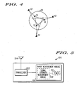
- FIG. 4 illustrates an example of two sequentially iterative estimates of locations within a sub-net 26, which attempts to minimize the difference between the measured ranges between units and calculated ranges between units, based upon estimated locations. As each new location or set of locations is estimated, a determination is made as to whether the calculated ranges between the units better matches the measured ranges between the units. As with some iterative approaches, each subsequent location estimate may be the result of a formula or function, which takes into account the previously determined difference(s).
- sub-nets 26 which separately determine a location estimate for each of the units within the respective sub-net 26 the amount of information and the delay associated with gathering the information can be reduced, which in turn minimizes the complexity of the calculations associated with estimating a location for each of the units in each of the sub-nets 26. Furthermore, the calculation in each of the sub-nets 26, in most instances, can proceed in parallel. In this way, an alternative approach for determining a location of a plurality of units in a network, which in many instances will represent an improvement, can be realized.
- FIG. 5 illustrates a block diagram of an exemplary unit 100, which in at least some instances will correspond to some of the units to be located 14 illustrated in FIGS. 1-4 .
- the units within a network 10 will communicate wirelessly.
- the unit 100 can include a transceiver 102 and an antenna 104.
- the unit 100 can include a transceiver 102 and an antenna 104.
- the exemplary unit 100 additionally include a range measurement module 106, which allows for a measured range determination between other units within communication range.
- a range measurement module 106 which allows for a measured range determination between other units within communication range.
- several different methods could be incorporated for determining range, at least a couple of examples include a range measurement based upon a received signal strength indication, time of arrival estimate, angle of arrival estimate, and/or a time difference of arrival estimate.
- the range measurement module 106 could include a signal strength measurement module 108.
- the range measurement module 106 could include a timer 110, which could be used in connection with determining a time of arrival estimate or a time difference of arrival estimate. The measured range information, is then used to determine a location estimate after the information is gathered in the unit 20, which is selected to estimate the location of the units in the sub-net 26.
- the range measurement module 106 may be implemented as one or more sets of prestored instructions, which are executed in a microprocessor. In other instances, the modules may be implemented using various electronic circuit elements.
- the block diagram illustrated in FIG. 5 may similarly correspond in some instances to one or more of the reference units 12, where it may be desirable for the reference units 12 to similarly be able to measure a range between nearby units.
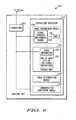
- FIG. 6 illustrates a block diagram of a unit 120, in accordance with at least one embodiment of the present invention, which is selected to determine a location estimate of the one or more units associated with at least one of the sub-nets, such as one or more of the units 100, illustrated in FIG. 5 .
- the selected unit 120 includes a transceiver 102, antenna 104, and range measurement module 106.
- the range measurement module 106 is optionally implemented as part of a centralized processor 122.
- the selected unit 120 may be a unit, which is not included among the units to be located 14 as part of a corresponding sub-net 26 or similarly may not be an associated reference unit. In these or similar instances, it may not be necessary for the selected unit 120 to include a range measurement module 106.
- the centralized processor 122 includes a storage unit 124, which is adapted for storing received range information 126.
- the storage unit 124 can take the form of one or more different types of storage including both volatile and non-volatile memory, at least a couple of examples including one or more types of semi-conductor memories (i.e. ROM, EPROM, RAM or EEPROM, etc.). Still further, the different types of storage could include auxiliary storage, such as fixed or removable media including magnetic disk or optical disc drives.
- the centralized processor 122 additionally includes an error determination module 128, which is adapted for determining a minimized error value associated with a set of estimated location values for the one or more units to be located 14, based upon the measured range information 126.
- the centralized processor 122 can further include a communication monitoring module 130, which is adapted to monitor communications between units for determining potential desirable break points 24, where the network could be beneficially sub-divided. As noted previously, both latency and traffic volume of the communication traffic associated with range information 126 could be monitored by the communication monitoring module 130 for purposes of making a decision relevant to potentially sub-dividing the network 10.
- the error determination module 128, communication monitoring module 130 and/or the range measurement module 106 could be implemented as one or more sets of prestored instructions 132 executed by one or more microprocessors or alternatively implemented using various circuit elements.
- the error determination module 128, communication monitoring module 130 and/or the range measurement module 106 could be implemented as one or more sets of prestored instructions 132 executed by one or more microprocessors or alternatively implemented using various circuit elements.
- One skilled in the art will readily recognize that still further alternative implementations are possible without departing from the teachings of the present invention.
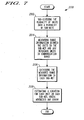
- FIG. 7 illustrates a flow diagram of a method 200 for determining a location of a plurality of units, in accordance with at least one embodiment of the present invention.
- the method generally includes sub-dividing 202 the plurality of units into a plurality of sub-nets 26. Additionally, range information between the units 14 in the sub-net 26 and any reference units 12 within communication range is measured 204. The range information is then gathered in a selected unit 20 associated with the corresponding sub-nets 26. A location is then estimated for each unit 14 to be located in each of the sub-nets 26, which minimizes an error value that is based on the range measurements.
- the error value is iteratively determined, where the error value is associated with the sum of a square of the differences between a distance associated with a measured range value and the distance associated with the currently known or estimated location of the units to be located.
- FIG. 8 illustrates a more specific flow diagram of sub-dividing 202 the plurality of units into a plurality of subnets 26, where the communication pathways are monitored, and communication pathways 16 having traffic volumes and/or latencies, which exceed a predetermined threshold are identified 210.
- a determination 212 is then made as to whether the traffic volume or latency exceeds a predetermined threshold. If the traffic volume or latency exceeds a predetermined threshold, in connection with any of the communication pathways 16, a sub-net boundary is defined 214 for a new sub-net 26. In this way, the need for different sub-nets can be identified and the boundaries for the different sub-nets 26 can be defined.
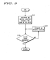
- FIG. 9 is a more specific flow diagram of estimating 208 a location for each of the units to be located 14 in at least a corresponding one of the sub-nets 26, in accordance with at least a still further embodiment of the present invention.
- an initial location estimate for each of the units within each of the corresponding sub-nets 26 is assigned 216, and an error estimate is determined, which is associated with the initial location estimates.
- an error estimate and error estimate determination can also be associated with a particular sub-net, and correspondingly be determined in parallel.
- a determination 218 is then made, as to whether the error has been minimized.
- this can be done by investigating potential changes in the location estimates for each of the units, and determining a corresponding change in the associated error value. Any improvements in the corresponding error values are then identified. If a potential improvement is detected, then a new location is estimated 220, which is associated with the improved error value. The process can be repeated until no further improvement in the error value and correspondingly the location estimate appears possible. In this way, a location estimate can be determined, based upon the measured range information, which can allow for separate processing in parallel of different sub-groups of the units 14 to be located.
- the method and system for determining a location for a plurality of units can be used in connection with the location of any number of individual items among a group of items, one such example including the detection of items in a storage location or in a warehouse environment.
- the method and system for determining a location has additional applicability in other networks, wherein the determination of the location of individual elements is desired and a corresponding set of reference units and other non-reference units are available throughout the area to assist in determining a location estimate.
- At least one such example includes the location of devices such as one or more cellular telephones or other wireless communication devices located within a network.
- the location determination module could be incorporated as part of the equipment for one or more groups of personnel operating in concert within a given area or environment.
- One such example includes emergency personnel.
- the circuitry and/or modules associated with each of the units could be located in one or more of a fire fighter's helmet, jacket, or other piece of equipment.
- the method and system for determining a location could be made to function with many different forms of wireless communications including communications systems, which use a cellular telephone radio transceiver, a cordless telephone radio transceiver, a wireless LAN connection, a short range radio transceiver, such as a Bluetooth transceiver, an infra-red communication transceiver, or other similar communication device. Still further there is no requirement that the units be completely physically detached from one another, for example, the method and system for determining a location could interact with an installed sprinkler system, which might include wireless transceivers, and/or which might be communicatively coupled to one another, via one or more common communication busses, which traverse the area containing the network.
- an installed sprinkler system which might include wireless transceivers, and/or which might be communicatively coupled to one another, via one or more common communication busses, which traverse the area containing the network.
Landscapes
- Physics & Mathematics (AREA)
- Engineering & Computer Science (AREA)
- General Physics & Mathematics (AREA)
- Radar, Positioning & Navigation (AREA)
- Remote Sensing (AREA)
- Mobile Radio Communication Systems (AREA)
- Position Fixing By Use Of Radio Waves (AREA)
Claims (21)
- Procédé permettant de déterminer un emplacement d'une pluralité d'unités (12, 14) dans un réseau à sauts multiples (10), chaque unité étant couplée en communication à au moins l'une de l'autre pluralité d'unités (12, 14), dans lequel au moins l'une de la pluralité d'unités (12, 14) est en plage de communication avec une ou plusieurs unités de référence (12) dont l'emplacement est au moins l'un d'un emplacement déterminé et connu, ledit procédé étant caractérisé par les étapes consistant à :subdiviser la pluralité d'unités (12, 14) en une pluralité de sous-réseaux (26), dans lequel chaque sous-réseau (26) comprend deux unités ou plus (étape 202) ;mesurer, dans chacun des sous-réseaux (26), l'information de plage entre chacune des unités dans le sous-réseau (26) et les autres unités dans le sous-réseau (26), qui sont en plage de communication avec l'unité, et l'information de plage entre toutes les unités de référence (12) et au moins l'une des unités dans le sous-réseau (26) dans la plage de communication de l'unité de référence correspondante (12) (étape 204) ;recueillir l'information de plage mesurée dans au moins une unité sélectionnée des unités (20) associées à chacun des sous-réseaux (26) (étape 206) ;estimer, dans la au moins une unité sélectionnée des unités (20) associées à chacun des sous-réseaux (26) dans lequel l'information de plage mesurée a été recueillie, un emplacement pour chacune des unités dans chacun des sous-réseaux (26), qui minimise une différence cumulée entre une distance entre les unités, en fonction des emplacements estimés, et une distance entre les unités, en fonction des plages mesurées entre les unités dans la plage de communication dans chacun des sous-réseaux (26) et la plage mesurée entre l'une quelconque des unités de référence (12) et les unités correspondantes dans le sous-réseau (26) dans la plage de communication d'au moins l'une des unités de référence (12) (étape 208).
- Procédé selon la revendication 1, dans lequel l'étape consistant à subdiviser la pluralité d'unités (12, 14) en une pluralité de sous-réseaux (26) comprend l'étape consistant à identifier des voies de passage de communication (22) entre les unités ayant au moins l'un parmi des volumes de trafic de communication et la latence de trafic de communication, associées à la détermination d'emplacement, qui dépasse un seuil prédéterminé correspondant et comprend les volumes de trafic de communication associés à la détermination d'emplacement pour au moins deux unités ; et l'étape consistant à définir une limite de sous-réseau (26) pour un nouveau sous-réseau (26) sur la voie de passage de communication (22) identifiée (étapes 210, 212, 214).
- Procédé selon la revendication 2, dans lequel l'étape consistant à définir une limite de sous-réseau (26) pour un nouveau sous-réseau (26) comprend l'étape consistant à définir un processeur centralisé (122) en tant que la au moins une unité sélectionnée des unités (20) pour le nouveau sous-réseau (26) parmi les deux unités ou plus dans le nouveau sous-réseau (26).
- Procédé selon la revendication 1, dans lequel l'étape consistant à mesurer, dans chacun des sous-réseaux (26), l'information de plage, comprend l'étape consistant à mesurer l'information de plage entre n'importe quel noeud proche à partir d'un sous-réseau voisin (26) et les unités dans le sous-réseau (26) dans la plage de communication du noeud proche correspondant à partir du sous-réseau (26) voisin.
- Procédé selon la revendication 1, dans lequel l'étape consistant à mesurer, dans chacun des sous-réseaux (26), l'information de plage, comprend l'étape consistant à mesurer au moins l'un parmi un indicateur de résistance de signal reçu, l'angle d'arrivée, le temps d'arrivée, la différence de temps d'arrivée et les décalages de phase pour les signaux transmis par une ou plusieurs des unités.
- Procédé selon la revendication 1, dans lequel l'étape consistant à recueillir l'information de plage mesurée dans au moins l'une des unités dans chacun des sous-réseaux comprend l'étape consistant à envoyer les estimations à la au moins une des unités en un ou plusieurs sauts via une ou plusieurs unités vers la au moins une unité sélectionnée des unités (20).
- Procédé selon la revendication 1, dans lequel l'étape consistant à estimer, dans la au moins une unité sélectionnée des unités (20) dans chacun des sous-réseaux (26), un emplacement pour chacune des unités dans chacun des sous-réseaux (26) comprend l'étape consistant à minimiser l'erreur dans un ensemble d'emplacements estimés pour chacune des unités et la plage mesurée entre les unités dans chaque sous-réseau (26).
- Procédé selon la revendication 7, dans lequel l'étape consistant à minimiser l'erreur comprend l'étape consistant à minimiser la somme du carré de la différence entre la plage, en fonction de l'emplacement estimé et la plage mesurée.
- Procédé selon la revendication 1, dans lequel l'étape consistant à estimer, dans la au moins une unité sélectionnée des unités (20) dans chacun des sous-réseaux (26), un emplacement pour chacune des unités dans chacun des sous-réseaux (26) comprend les unités sélectionnées des unités (20) dans chacun des sous-réseaux (26), l'étape consistant à attribuer une estimation d'emplacement initiale pour chacune des unités dans le sous-réseau (26) correspondant et l'étape consistant à estimer de manière itérative un emplacement mis à jour pour chacune des unités dans le sous-réseau (26) correspondant (étapes 216, 218, 220).
- Procédé selon la revendication 9, dans lequel, avant chaque estimation itérative, l'unité sélectionnée des unités (20) dans chacun des sous-réseaux (26) communique l'information d'emplacement estimée courante des unités dans le sous-réseau (26) correspondant, utilisée dans l'estimation d'emplacement des unités dans les autres sous-réseaux (26), aux unités sélectionnées des unités dans les autres sous-réseaux (26).
- Procédé selon la revendication 1, dans lequel une unité de référence (12) pour un sous-réseau (26) comprend une unité dont l'emplacement est estimé comme faisant partie d'un autre sous-réseau (26).
- Système pour déterminer l'emplacement d'une pluralité d'unités (12, 14) dans un réseau à sauts multiples (10), chaque unité étant couplée en communication à au moins l'une de l'autre pluralité d'unités (12, 14), dans lequel au moins l'une de la pluralité d'unités (12, 14) est en plage de communication avec une ou plusieurs unités de référence (12) dont l'emplacement est au moins l'un parmi un emplacement déterminé et connu, ledit système étant caractérisé par :une pluralité de sous-réseaux (26) qui ont été formés en subdivisant la pluralité d'unités (12, 14) dans le réseau à sauts multiples, chaque sous-réseau (26) comprenant une pluralité d'unités (12, 14) ayant un émetteur - récepteur (102) pour partager l'information comprenant l'information d'emplacement, avec d'autres unités, dans lequel au moins l'une desdites unités associées à chacun desdits sous-réseaux (26) comprend un processeur centralisé (122) adapté pour recevoir l'information de plage de chacune des unités dans le sous-réseau (26) correspondant dans un ou plusieurs sauts, et adapté pour estimer l'emplacement de chacune des unités dans le sous-réseau (26) correspondant uniquement en fonction de l'information de plage reçue de chacune des unités dans le sous-réseau (26) correspondant qui a été mesuré par chacune des unités dans le sous-réseau (26) correspondant, qui minimise une différence cumulée entre une distance entre les unités, en fonction des emplacements estimés, et une distance entre les unités, en fonction des plages mesurées entre les unités dans la plage de communication dans chacun des sous-réseaux (26) et la plage mesurée entre l'une quelconque des unités de référence et les unités correspondantes dans le sous-réseau (26).
- Système selon la revendication 12, dans lequel chaque unité comprend un module de mesure de plage couplé à l'émetteur - récepteur (102) pour détecter la plage entre chacune des unités dans un sous-réseau (26) et les autres unités dans le sous-réseau (26), qui sont dans la plage de communication avec l'unité, et la plage entre n'importe quelle unité de référence (12) dans la plage de communication avec l'unité.
- Système selon la revendication 13, dans lequel le module de mesure de plage (106) comprend une minuterie pour déterminer au moins l'un parmi le temps d'arrivée et la différence de temps d'arrivée des signaux transmis par les autres unités dans la plage de communication.
- Système selon la revendication 13, dans lequel le module de mesure de plage (106) est adapté pour mesurer le décalage de phase des signaux transmis par les autres unités dans la plage de communication.
- Système selon la revendication 13, dans lequel le module de mesure de plage (106) comprend un module de mesure de résistance de signal (108) pour détecter la résistance de signal reçu des signaux transmis par les autres unités dans la plage de communication.
- Système selon la revendication 13, dans lequel chacun desdits processeurs centralisés (122) comprend un module de détermination d'erreur (128) adapté pour déterminer une erreur basée sur la différence entre la plage informatisée calculée à partir de l'emplacement estimé des unités dans le sous-réseau (26) correspondant et l'emplacement reçu de n'importe quelle unité de référence (12) et une plage mesurée correspondante.
- Système selon la revendication 12, comprenant en outre un module de surveillance de communication (130) pour identifier le volume de trafic d'information associé à l'information d'emplacement communiquée le long des voies de passage (22) entre les noeuds.
- Système selon la revendication 12, dans lequel au moins l'une des unités est un dispositif de communication mobile.
- Système selon la revendication 19, dans lequel au moins l'un des dispositifs de communication mobiles est un radiotéléphone cellulaire.
- Système selon la revendication 12, dans lequel au moins l'une des unités comprend un équipement utilisé par un groupe d'individus agissant de concert.
Applications Claiming Priority (2)
| Application Number | Priority Date | Filing Date | Title |
|---|---|---|---|
| US10/747,378 US7274940B2 (en) | 2003-12-29 | 2003-12-29 | Method and system for determining a location of a plurality of units using sub-divided unit groupings |
| PCT/US2004/042244 WO2005065202A2 (fr) | 2003-12-29 | 2004-12-15 | Procede et dispositif permettant de determiner l'emplacement d'unites en utilisant des groupes subdivises d'unites |
Publications (3)
| Publication Number | Publication Date |
|---|---|
| EP1700496A2 EP1700496A2 (fr) | 2006-09-13 |
| EP1700496A4 EP1700496A4 (fr) | 2007-11-28 |
| EP1700496B1 true EP1700496B1 (fr) | 2009-07-22 |
Family
ID=34700739
Family Applications (1)
| Application Number | Title | Priority Date | Filing Date |
|---|---|---|---|
| EP04814431A Expired - Lifetime EP1700496B1 (fr) | 2003-12-29 | 2004-12-15 | Procede et dispositif permettant de determiner l'emplacement d'unites en utilisant des groupes subdivises d'unites |
Country Status (6)
| Country | Link |
|---|---|
| US (1) | US7274940B2 (fr) |
| EP (1) | EP1700496B1 (fr) |
| CN (1) | CN1902955B (fr) |
| AT (1) | ATE437503T1 (fr) |
| DE (1) | DE602004022196D1 (fr) |
| WO (1) | WO2005065202A2 (fr) |
Families Citing this family (20)
| Publication number | Priority date | Publication date | Assignee | Title |
|---|---|---|---|---|
| US7092726B2 (en) * | 2003-12-29 | 2006-08-15 | Motorola, Inc. | Method and system for determining a location using a plurality of selected initial location estimates |
| US7099676B2 (en) * | 2004-04-09 | 2006-08-29 | Sony Corporation | System and method for location and motion detection in a home wireless network |
| US8041469B2 (en) * | 2005-01-05 | 2011-10-18 | GM Global Technology Operations LLC | Determining relative spatial information between vehicles |
| US7697941B2 (en) * | 2005-08-02 | 2010-04-13 | Sony Ericsson Mobile Communications Ab | Updating presence in a wireless communications device |
| US20070239350A1 (en) * | 2006-04-07 | 2007-10-11 | Zumsteg Philip J | Multi-function tracking device with robust asset tracking system |
| US8059662B2 (en) * | 2006-04-18 | 2011-11-15 | Harris Corporation | System and method for controlling content and delivery of internet protocol television (IPTV) services |
| US8364166B2 (en) * | 2008-04-21 | 2013-01-29 | Qualcomm Incorporated | System and method of position location transfer |
| WO2009155036A2 (fr) * | 2008-05-28 | 2009-12-23 | Nivis, Llc | Procédés et systèmes d'estimation de position |
| US8068851B2 (en) * | 2008-08-29 | 2011-11-29 | Motorola Solutions, Inc. | Method for proximity detection in a wireless communication network |
| US8812013B2 (en) * | 2008-10-27 | 2014-08-19 | Microsoft Corporation | Peer and composite localization for mobile applications |
| DE102009009188B4 (de) * | 2009-02-16 | 2011-09-01 | Airbus Operations Gmbh | Sensornetzwerk für ein Flugzeug zur Lokalisierung von Geräten |
| FR2958111A1 (fr) * | 2010-03-29 | 2011-09-30 | Commissariat Energie Atomique | Procede de determination de parametres de disposition absolue d'objets, programme d'ordinateur associe et installation de controle |
| FR2965060B1 (fr) * | 2010-09-16 | 2012-10-05 | Commissariat Energie Atomique | Procede et dispositif de localisation cooperative d'emetteurs et/ou recepteurs compris par un corps mobile |
| US9674661B2 (en) | 2011-10-21 | 2017-06-06 | Microsoft Technology Licensing, Llc | Device-to-device relative localization |
| US20140087763A1 (en) * | 2012-09-24 | 2014-03-27 | Qualcomm Incorporated | Non-geotagged access point positioning |
| WO2014179529A1 (fr) * | 2013-05-02 | 2014-11-06 | Consortium P, Inc. | Détection de position en temps réel pouvant être échelonnée et basée sur des réseaux neuraux se chevauchant |
| US9467965B2 (en) * | 2013-08-14 | 2016-10-11 | Marvell World Trade Ltd. | Positioning data distribution applied to server-based positioning system |
| US9775007B2 (en) * | 2013-10-09 | 2017-09-26 | Mediatek Singapore Pte. Ltd. | Group based location service in wireless local area networks |
| CN110225451B (zh) * | 2019-06-19 | 2021-02-02 | 京东方科技集团股份有限公司 | 基于无线自组网的节点定位方法及装置、电子设备、介质 |
| US11405894B2 (en) | 2019-07-09 | 2022-08-02 | Samsung Electronics Co., Ltd. | System and method of establishing communication for exchanging ranging information |
Family Cites Families (8)
| Publication number | Priority date | Publication date | Assignee | Title |
|---|---|---|---|---|
| US6236662B1 (en) * | 1998-05-04 | 2001-05-22 | Bae Systems Aerospace Inc. | Multirate time reservation multi-access protocol |
| US6980524B1 (en) * | 1999-05-20 | 2005-12-27 | Polytechnic University | Methods and apparatus for routing in a mobile ad hoc network |
| US6859831B1 (en) * | 1999-10-06 | 2005-02-22 | Sensoria Corporation | Method and apparatus for internetworked wireless integrated network sensor (WINS) nodes |
| US6473038B2 (en) * | 2001-01-05 | 2002-10-29 | Motorola, Inc. | Method and apparatus for location estimation |
| US7161926B2 (en) * | 2001-07-03 | 2007-01-09 | Sensoria Corporation | Low-latency multi-hop ad hoc wireless network |
| US7277414B2 (en) * | 2001-08-03 | 2007-10-02 | Honeywell International Inc. | Energy aware network management |
| US6807158B2 (en) * | 2001-08-07 | 2004-10-19 | Hrl Laboratories, Llc | Method and apparatus for determining position and trajectory of gateways to optimize performance in hybrid non-terrestrial-terrestrial multi-hop mobile networks |
| US7123925B2 (en) * | 2002-06-18 | 2006-10-17 | British Telecommunications Public Limited Company | Method and apparatus for locating devices |
-
2003
- 2003-12-29 US US10/747,378 patent/US7274940B2/en not_active Expired - Lifetime
-
2004
- 2004-12-15 EP EP04814431A patent/EP1700496B1/fr not_active Expired - Lifetime
- 2004-12-15 CN CN2004800393679A patent/CN1902955B/zh not_active Expired - Lifetime
- 2004-12-15 WO PCT/US2004/042244 patent/WO2005065202A2/fr not_active Ceased
- 2004-12-15 DE DE602004022196T patent/DE602004022196D1/de not_active Expired - Fee Related
- 2004-12-15 AT AT04814431T patent/ATE437503T1/de not_active IP Right Cessation
Also Published As
| Publication number | Publication date |
|---|---|
| CN1902955B (zh) | 2010-06-16 |
| WO2005065202A2 (fr) | 2005-07-21 |
| DE602004022196D1 (de) | 2009-09-03 |
| WO2005065202A3 (fr) | 2005-12-01 |
| EP1700496A2 (fr) | 2006-09-13 |
| EP1700496A4 (fr) | 2007-11-28 |
| CN1902955A (zh) | 2007-01-24 |
| US7274940B2 (en) | 2007-09-25 |
| ATE437503T1 (de) | 2009-08-15 |
| US20050143101A1 (en) | 2005-06-30 |
Similar Documents
| Publication | Publication Date | Title |
|---|---|---|
| EP1700496B1 (fr) | Procede et dispositif permettant de determiner l'emplacement d'unites en utilisant des groupes subdivises d'unites | |
| CN1998251B (zh) | 用于使用近邻列表确定单元位置的方法和装置 | |
| US8175613B2 (en) | Systems and methods for determining location of devices within a wireless network | |
| US6973039B2 (en) | Mechanism for performing energy-based routing in wireless networks | |
| US6885969B2 (en) | Location estimation in partially synchronized networks | |
| KR101020859B1 (ko) | 무선센서 네트워크에서의 노드간 거리 검출 방법 및 그 시스템 | |
| JP6325491B2 (ja) | 無線ネットワークでの位置検出 | |
| EP1700495B1 (fr) | Procede et systeme permettant de determiner une positions a l'aide d'une pluralite d'estimations de positions initiales selectionnees | |
| US8380218B2 (en) | Transponder subsystem for supporting location awareness in wireless networks | |
| US20070041352A1 (en) | Elevator calling mechanism and method | |
| US20050261004A1 (en) | Wireless node location mechanism featuring definition of search region to optimize location computation | |
| CN105704677B (zh) | 一种基于气压计的室内定位方法及装置 | |
| US10976403B2 (en) | Position detection system and receiver | |
| WO2009075431A1 (fr) | Système et procédé pour la localisation de position d'objet en mouvement | |
| KR102261085B1 (ko) | 위치 추정 방법 및 이를 지원하는 장치 | |
| CN113126026A (zh) | 定位系统、方法及存储介质 | |
| US20240422549A1 (en) | Self-organized mesh network | |
| JP2005123833A (ja) | 位置検出システム制御方法 | |
| CN109587626A (zh) | 面向凹型区域的无线传感器网络邻居节点距离估计方法 | |
| CN105898858B (zh) | 一种不依赖于邻居节点的apit节点定位系统及方法 | |
| KR101901359B1 (ko) | 이동 노드를 이용한 수동적 위치 추적 시스템 및 방법 | |
| Li et al. | Mobile-beacon assisted sensor localization with dynamic beacon mobility scheduling | |
| KR102275306B1 (ko) | Ap 위치 관리 장치 및 방법 | |
| Moayeri | Mission-Critical Networking and Situation-Awareness | |
| Rashid | Localization in wireless sensor networks |
Legal Events
| Date | Code | Title | Description |
|---|---|---|---|
| PUAI | Public reference made under article 153(3) epc to a published international application that has entered the european phase |
Free format text: ORIGINAL CODE: 0009012 |
|
| 17P | Request for examination filed |
Effective date: 20060622 |
|
| AK | Designated contracting states |
Kind code of ref document: A2 Designated state(s): AT BE BG CH CY CZ DE DK EE ES FI FR GB GR HU IE IS IT LI LT LU MC NL PL PT RO SE SI SK TR |
|
| DAX | Request for extension of the european patent (deleted) | ||
| A4 | Supplementary search report drawn up and despatched |
Effective date: 20071026 |
|
| RIC1 | Information provided on ipc code assigned before grant |
Ipc: H04L 12/56 20060101AFI20071022BHEP |
|
| 17Q | First examination report despatched |
Effective date: 20080227 |
|
| GRAP | Despatch of communication of intention to grant a patent |
Free format text: ORIGINAL CODE: EPIDOSNIGR1 |
|
| GRAS | Grant fee paid |
Free format text: ORIGINAL CODE: EPIDOSNIGR3 |
|
| GRAA | (expected) grant |
Free format text: ORIGINAL CODE: 0009210 |
|
| AK | Designated contracting states |
Kind code of ref document: B1 Designated state(s): AT BE BG CH CY CZ DE DK EE ES FI FR GB GR HU IE IS IT LI LT LU MC NL PL PT RO SE SI SK TR |
|
| REG | Reference to a national code |
Ref country code: GB Ref legal event code: FG4D |
|
| REG | Reference to a national code |
Ref country code: CH Ref legal event code: EP |
|
| REG | Reference to a national code |
Ref country code: IE Ref legal event code: FG4D |
|
| REF | Corresponds to: |
Ref document number: 602004022196 Country of ref document: DE Date of ref document: 20090903 Kind code of ref document: P |
|
| REG | Reference to a national code |
Ref country code: GR Ref legal event code: EP Ref document number: 20090402603 Country of ref document: GR |
|
| NLV1 | Nl: lapsed or annulled due to failure to fulfill the requirements of art. 29p and 29m of the patents act | ||
| PG25 | Lapsed in a contracting state [announced via postgrant information from national office to epo] |
Ref country code: SE Free format text: LAPSE BECAUSE OF FAILURE TO SUBMIT A TRANSLATION OF THE DESCRIPTION OR TO PAY THE FEE WITHIN THE PRESCRIBED TIME-LIMIT Effective date: 20090722 Ref country code: LT Free format text: LAPSE BECAUSE OF FAILURE TO SUBMIT A TRANSLATION OF THE DESCRIPTION OR TO PAY THE FEE WITHIN THE PRESCRIBED TIME-LIMIT Effective date: 20090722 Ref country code: ES Free format text: LAPSE BECAUSE OF FAILURE TO SUBMIT A TRANSLATION OF THE DESCRIPTION OR TO PAY THE FEE WITHIN THE PRESCRIBED TIME-LIMIT Effective date: 20091102 Ref country code: IS Free format text: LAPSE BECAUSE OF FAILURE TO SUBMIT A TRANSLATION OF THE DESCRIPTION OR TO PAY THE FEE WITHIN THE PRESCRIBED TIME-LIMIT Effective date: 20091122 Ref country code: FI Free format text: LAPSE BECAUSE OF FAILURE TO SUBMIT A TRANSLATION OF THE DESCRIPTION OR TO PAY THE FEE WITHIN THE PRESCRIBED TIME-LIMIT Effective date: 20090722 Ref country code: AT Free format text: LAPSE BECAUSE OF FAILURE TO SUBMIT A TRANSLATION OF THE DESCRIPTION OR TO PAY THE FEE WITHIN THE PRESCRIBED TIME-LIMIT Effective date: 20090722 |
|
| PG25 | Lapsed in a contracting state [announced via postgrant information from national office to epo] |
Ref country code: PL Free format text: LAPSE BECAUSE OF FAILURE TO SUBMIT A TRANSLATION OF THE DESCRIPTION OR TO PAY THE FEE WITHIN THE PRESCRIBED TIME-LIMIT Effective date: 20090722 Ref country code: NL Free format text: LAPSE BECAUSE OF FAILURE TO SUBMIT A TRANSLATION OF THE DESCRIPTION OR TO PAY THE FEE WITHIN THE PRESCRIBED TIME-LIMIT Effective date: 20090722 Ref country code: SI Free format text: LAPSE BECAUSE OF FAILURE TO SUBMIT A TRANSLATION OF THE DESCRIPTION OR TO PAY THE FEE WITHIN THE PRESCRIBED TIME-LIMIT Effective date: 20090722 |
|
| PG25 | Lapsed in a contracting state [announced via postgrant information from national office to epo] |
Ref country code: PT Free format text: LAPSE BECAUSE OF FAILURE TO SUBMIT A TRANSLATION OF THE DESCRIPTION OR TO PAY THE FEE WITHIN THE PRESCRIBED TIME-LIMIT Effective date: 20091122 Ref country code: BG Free format text: LAPSE BECAUSE OF FAILURE TO SUBMIT A TRANSLATION OF THE DESCRIPTION OR TO PAY THE FEE WITHIN THE PRESCRIBED TIME-LIMIT Effective date: 20091022 |
|
| PG25 | Lapsed in a contracting state [announced via postgrant information from national office to epo] |
Ref country code: RO Free format text: LAPSE BECAUSE OF FAILURE TO SUBMIT A TRANSLATION OF THE DESCRIPTION OR TO PAY THE FEE WITHIN THE PRESCRIBED TIME-LIMIT Effective date: 20090722 Ref country code: EE Free format text: LAPSE BECAUSE OF FAILURE TO SUBMIT A TRANSLATION OF THE DESCRIPTION OR TO PAY THE FEE WITHIN THE PRESCRIBED TIME-LIMIT Effective date: 20090722 Ref country code: CZ Free format text: LAPSE BECAUSE OF FAILURE TO SUBMIT A TRANSLATION OF THE DESCRIPTION OR TO PAY THE FEE WITHIN THE PRESCRIBED TIME-LIMIT Effective date: 20090722 Ref country code: DK Free format text: LAPSE BECAUSE OF FAILURE TO SUBMIT A TRANSLATION OF THE DESCRIPTION OR TO PAY THE FEE WITHIN THE PRESCRIBED TIME-LIMIT Effective date: 20090722 |
|
| PLBE | No opposition filed within time limit |
Free format text: ORIGINAL CODE: 0009261 |
|
| STAA | Information on the status of an ep patent application or granted ep patent |
Free format text: STATUS: NO OPPOSITION FILED WITHIN TIME LIMIT |
|
| PG25 | Lapsed in a contracting state [announced via postgrant information from national office to epo] |
Ref country code: SK Free format text: LAPSE BECAUSE OF FAILURE TO SUBMIT A TRANSLATION OF THE DESCRIPTION OR TO PAY THE FEE WITHIN THE PRESCRIBED TIME-LIMIT Effective date: 20090722 Ref country code: BE Free format text: LAPSE BECAUSE OF FAILURE TO SUBMIT A TRANSLATION OF THE DESCRIPTION OR TO PAY THE FEE WITHIN THE PRESCRIBED TIME-LIMIT Effective date: 20090722 |
|
| 26N | No opposition filed |
Effective date: 20100423 |
|
| PG25 | Lapsed in a contracting state [announced via postgrant information from national office to epo] |
Ref country code: MC Free format text: LAPSE BECAUSE OF NON-PAYMENT OF DUE FEES Effective date: 20100701 |
|
| REG | Reference to a national code |
Ref country code: CH Ref legal event code: PL |
|
| PG25 | Lapsed in a contracting state [announced via postgrant information from national office to epo] |
Ref country code: IE Free format text: LAPSE BECAUSE OF NON-PAYMENT OF DUE FEES Effective date: 20091215 Ref country code: CH Free format text: LAPSE BECAUSE OF NON-PAYMENT OF DUE FEES Effective date: 20091231 Ref country code: LI Free format text: LAPSE BECAUSE OF NON-PAYMENT OF DUE FEES Effective date: 20091231 |
|
| PG25 | Lapsed in a contracting state [announced via postgrant information from national office to epo] |
Ref country code: DE Free format text: LAPSE BECAUSE OF NON-PAYMENT OF DUE FEES Effective date: 20100701 |
|
| PG25 | Lapsed in a contracting state [announced via postgrant information from national office to epo] |
Ref country code: LU Free format text: LAPSE BECAUSE OF NON-PAYMENT OF DUE FEES Effective date: 20091215 |
|
| REG | Reference to a national code |
Ref country code: FR Ref legal event code: CD |
|
| PG25 | Lapsed in a contracting state [announced via postgrant information from national office to epo] |
Ref country code: HU Free format text: LAPSE BECAUSE OF FAILURE TO SUBMIT A TRANSLATION OF THE DESCRIPTION OR TO PAY THE FEE WITHIN THE PRESCRIBED TIME-LIMIT Effective date: 20100123 |
|
| PG25 | Lapsed in a contracting state [announced via postgrant information from national office to epo] |
Ref country code: TR Free format text: LAPSE BECAUSE OF FAILURE TO SUBMIT A TRANSLATION OF THE DESCRIPTION OR TO PAY THE FEE WITHIN THE PRESCRIBED TIME-LIMIT Effective date: 20090722 |
|
| PG25 | Lapsed in a contracting state [announced via postgrant information from national office to epo] |
Ref country code: CY Free format text: LAPSE BECAUSE OF FAILURE TO SUBMIT A TRANSLATION OF THE DESCRIPTION OR TO PAY THE FEE WITHIN THE PRESCRIBED TIME-LIMIT Effective date: 20090722 |
|
| REG | Reference to a national code |
Ref country code: FR Ref legal event code: PLFP Year of fee payment: 12 |
|
| REG | Reference to a national code |
Ref country code: FR Ref legal event code: PLFP Year of fee payment: 13 |
|
| REG | Reference to a national code |
Ref country code: FR Ref legal event code: PLFP Year of fee payment: 14 |
|
| REG | Reference to a national code |
Ref country code: FR Ref legal event code: CA Effective date: 20180105 |
|
| REG | Reference to a national code |
Ref country code: FR Ref legal event code: TP Owner name: ARRIS ENTERPRISES LLC, US Effective date: 20180807 |
|
| REG | Reference to a national code |
Ref country code: GB Ref legal event code: 732E Free format text: REGISTERED BETWEEN 20220317 AND 20220323 |
|
| PGFP | Annual fee paid to national office [announced via postgrant information from national office to epo] |
Ref country code: GR Payment date: 20231229 Year of fee payment: 20 Ref country code: GB Payment date: 20231227 Year of fee payment: 20 |
|
| PGFP | Annual fee paid to national office [announced via postgrant information from national office to epo] |
Ref country code: IT Payment date: 20231220 Year of fee payment: 20 Ref country code: FR Payment date: 20231227 Year of fee payment: 20 |
|
| REG | Reference to a national code |
Ref country code: GB Ref legal event code: PE20 Expiry date: 20241214 |
|
| PG25 | Lapsed in a contracting state [announced via postgrant information from national office to epo] |
Ref country code: GB Free format text: LAPSE BECAUSE OF EXPIRATION OF PROTECTION Effective date: 20241214 |
|
| PG25 | Lapsed in a contracting state [announced via postgrant information from national office to epo] |
Ref country code: GB Free format text: LAPSE BECAUSE OF EXPIRATION OF PROTECTION Effective date: 20241214 |